


About Timer Relays
More
Choosing an Electrical Switch
More
Wireless Light Switches
Control lights by transmitting a wireless signal from these switches to a control relay (sold separately) on your fixture. Switches can be surface mounted with a wall plate or used as a hand-held remote. No batteries or secondary power source are needed.

| No. of Circuits Controlled | Color | Max. Transmission Distance, ft. | Transmission Frequency | Includes | Each | |
| 1 | White | 150 | 902 MHz | One Switch, One Wall Plate | 0000000 | 0000000 |

| No. of Circuits Controlled | Switch Starting Position | Industry Designation | Input Voltage | Switching Current @ Voltage | Wire Lead Lg. | Each | |
| 1 | 1 Off (Normally Open) | SPST-NO | 120V AC | 5 A @ 120 V AC/277 V AC | 16" | 0000000 | 0000000 |
| 1 | 1 Off (Normally Open) | SPST-NO | 208V AC/277V AC | 5 A @ 120 V AC/277 V AC | 16" | 0000000 | 000000 |
| 1 | 1 Off (Normally Open) or 1 On (Normally Closed) | SPDT | 120V AC | 10 A @ 120 V AC, 20 A @ 277 V AC | 16" | 0000000 | 000000 |
| 1 | 1 Off (Normally Open) or 1 On (Normally Closed) | SPDT | 277V AC | 10 A @ 120 V AC, 20 A @ 277 V AC | 16" | 0000000 | 000000 |
| Color | Each | |
| White | 0000000 | 00000 |
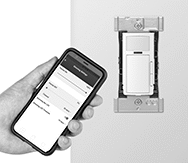
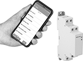
Smart Light Switches
Flip a switch from here, there, or anywhere—these switches connect wirelessly to your phone or smart device. Use the downloadable app and built-in Wi-Fi connection to quickly sync these switches to your device. Not only can you turn the lights on and off from the app, but you can also program a lighting schedule that doesn't interfere with manual use. For example, set your lights to turn off automatically at the end of a shift. Someone working in the area can still turn them on or off throughout the day.
Install up to three switch companions to manually turn the lights on and off from multiple locations, just like a multi-way switch. No extra wiring is necessary—these connect wirelessly to the smart switch. Mount them directly to any interior wall surface or an existing outlet box.

| No. of Circuits Controlled | Color | Switch Action | Switching Current @ Voltage | Wire Connection Type | For Max. No. of Companion Switches | Mounting Location | Operating System Compatibility | Specifications Met | Each | |
| 1 | White | Stays Switched (Maintained) | 15 A @ 120 V AC | Wire Leads | 3 | Outlet Box | Android 8.0 or Later, iOS 12.0 or Later | CSA Certified, CSA-US Certified | 0000000 | 000000 |

| Color | Switch Action | Max. Transmission Distance, ft. | Mounting Location | Batteries Included | Specifications Met | Each | |
| White | Stays Switched (Maintained) | 50 | Outlet Box, Wall | Yes | CSA Certified, CSA-US Certified | 0000000 | 000000 |
Smart Wall-Mount Motion-Sensing Light Controls

Customize motion-sensing light controls from your smartphone or tablet. These light controls connect to a free downloadable app using Bluetooth. Use the app to set schedules, control multiple lights remotely, and override the sensor function so you can manually turn lights on or off in the room. Also known as occupancy sensors, they also work without the app—they turn lights on when they detect movement and off when the area is unoccupied. These light controls fit in standard wall plates.
Controls with infrared sensors detect changes in heat sources and require a direct view of people occupying the space to activate.
Controls with infrared/ultrasonic sensors minimize false activation by detecting changes in heat sources and motion. They can be set so that only one or both detection methods are required to activate and hold lights on.
![]() For technical drawings and 3-D models, click on a part number.
For technical drawings and 3-D models, click on a part number.
| For Bulb Type | Coverage, sq. ft. | No. of Circuits Controlled | Input Voltage | Max. Mounting Ht., ft. | Wire Connection Type | Specifications Met | Each | |
Ivory | ||||||||
|---|---|---|---|---|---|---|---|---|
Bluetooth Connection | ||||||||
Infrared Sensor | ||||||||
| Incandescent, CFL, Halogen, LED | 1,100 | 1 | 120V AC | 4 | Wire Leads | UL Listed, C-UL Listed | 00000000 | 000000 |
| Incandescent, CFL, Halogen, LED | 1,100 | 1 | 120V AC 208V AC 240V AC 277V AC | 4 | Wire Leads | UL Listed, C-UL Listed | 00000000 | 00000 |
Infrared/Ultrasonic Sensor | ||||||||
| Incandescent, CFL, Halogen, LED | 1,100 | 1 | 120V AC 208V AC 240V AC 277V AC | 4 | Wire Leads | UL Listed, C-UL Listed | 00000000 | 00000 |
White | ||||||||
Bluetooth Connection | ||||||||
Infrared Sensor | ||||||||
| Incandescent, CFL, Halogen, LED | 1,100 | 1 | 120V AC | 4 | Wire Leads | UL Listed, C-UL Listed | 00000000 | 00000 |
| Incandescent, CFL, Halogen, LED | 1,100 | 1 | 120V AC 208V AC 240V AC 277V AC | 4 | Wire Leads | UL Listed, C-UL Listed | 00000000 | 00000 |
Infrared/Ultrasonic Sensor | ||||||||
| Incandescent, CFL, Halogen, LED | 1,100 | 1 | 120V AC 208V AC 240V AC 277V AC | 4 | Wire Leads | UL Listed, C-UL Listed | 00000000 | 00000 |
Smart Wall-Mount Motion-Sensing Light Dimmers
Control the brightness of lights from your smartphone. Using a Bluetooth-connected app on your phone or tablet, you can schedule when lights turn on, adjust their brightness levels, and set their movement sensitivity. Also known as occupancy sensors, these dimmers turn lights on when motion is detected and off when people are away. You can override the motion sensor function with a tap on the app to manually switch or dim lights. They fit in standard wall plates.
Dimmers with infrared sensors detect changes in heat sources and require a direct view of people occupying the space to activate.
Dimmers with infrared/ultrasonic sensors minimize false activation by detecting changes in heat sources and motion. They can be set so that only one or both detection methods are required to activate and hold lights on.
For light controls with DC input voltage, you'll need a power controller to switch a 120V or 277V AC lighting circuit. Power controllers have a relay that switches a maximum 20-amp load.
![]() For technical drawings and 3-D models, click on a part number.
For technical drawings and 3-D models, click on a part number.
Light Dimmers | Power Controllers | |||||||||||||
|---|---|---|---|---|---|---|---|---|---|---|---|---|---|---|
| For Bulb Type | Coverage, sq. ft. | No. of Circuits Controlled | Input Voltage | Max. Mounting Ht., ft. | Ht. | Wd. | Dp. | Wire Connection Type | Specifications Met | Choose a Color | Each | Each | ||
Bluetooth Connection | ||||||||||||||
Infrared Sensor | ||||||||||||||
| Incandescent, Halogen, CFL, LED | 1,100 | 1 | 12V AC/12V DC/24V AC/24V DC | 4 | 4 1/8" | 2 1/8" | 1 7/8" | Wire Leads | UL Listed, C-UL Listed | White | 00000000 | 000000 | 0000000 | 000000 |
| Incandescent, CFL, LED | 1,100 | 1 | 120V AC | 4 | 4 1/8" | 2 1/8" | 1 7/8" | Wire Leads | UL Listed, C-UL Listed | 00000000 | 00000 | 000000 | 00 | |
| LED | 1,100 | 1 | 120V AC/208V AC/240V AC/277V AC | 4 | 4 1/8" | 2 1/8" | 1 7/8" | Wire Leads | UL Listed, C-UL Listed | White | 00000000 | 000000 | 000000 | 00 |
Infrared/Ultrasonic Sensor | ||||||||||||||
| Incandescent, Halogen, CFL, LED | 1,100 | 1 | 12V DC/24V DC | 4 | 4 1/8" | 2 1/8" | 1 7/8" | Wire Leads | UL Listed, C-UL Listed | White | 00000000 | 000000 | 0000000 | 00000 |
| Incandescent, CFL, LED | 1,100 | 1 | 120V AC | 4 | 4 1/8" | 2 1/8" | 1 7/8" | Wire Leads | UL Listed, C-UL Listed | 00000000 | 000000 | 000000 | 00 | |
| LED | 1,100 | 1 | 120V AC/208V AC/240V AC/277V AC | 4 | 4 1/8" | 2 1/8" | 1 7/8" | Wire Leads | UL Listed, C-UL Listed | 00000000 | 000000 | 000000 | 00 | |
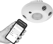
Smart Ceiling-Mount Motion-Sensing Light Controls
Fine-tune motion-sensing light controls from your smartphone or tablet. Mounting on the ceiling gives these light controls a clearer view of the room than wall-mount sensors, so they detect motion over a larger area. They connect to a free downloadable app using Bluetooth. Use the app to adjust the amount of time lights stay on after people leave, set schedules, or override the sensor so lights are always on. Also known as occupancy sensors, they turn lights on when they sense movement and off after people leave.
Controls with infrared sensors detect changes in heat sources and need a direct view of people.
Controls with infrared/ultrasonic sensors have two detection methods to minimize false activation: infrared to sense heat sources and ultrasonic to sense motion. Use the app to adjust whether both or just one of these triggers will switch the lights.
Controls with a dimmer let you adjust the brightness of your lights.
![]() For technical drawings and 3-D models, click on a part number.
For technical drawings and 3-D models, click on a part number.
| For Bulb Type | Coverage, sq. ft. | No. of Circuits Controlled | For Max. No. of Companion Switches | Input Voltage | Max. Mounting Ht., ft. | Color | Housing Material | Ht. | Dia. | Wire Connection Type | Specifications Met | Each | |
Bluetooth Connection | |||||||||||||
|---|---|---|---|---|---|---|---|---|---|---|---|---|---|
Infrared Sensor | |||||||||||||
| Incandescent, CFL, Halogen, LED | 1,500 | 1 | 4 | 120V AC 277V AC | 20 | White | Plastic | 2 3/8" | 4 13/16" | Screw Terminals | UL Listed, C-UL Listed | 0000000 | 0000000 |
Infrared Sensor with Dimmer Switch | |||||||||||||
| Incandescent, CFL, Halogen, LED | 1,500 | 2 | 4 | 120V AC 277V AC | 20 | White | Plastic | 2 3/8" | 4 13/16" | Screw Terminals | UL Listed, C-UL Listed | 0000000 | 000000 |
Infrared/Ultrasonic Sensor | |||||||||||||
| Incandescent, CFL, Halogen, LED | 500 | 1 | 4 | 120V AC 277V AC | 20 | White | Plastic | 2 3/8" | 4 13/16" | Screw Terminals | UL Listed, C-UL Listed | 0000000 | 000000 |
| Incandescent, CFL, Halogen, LED | 500 | 2 | 4 | 120V AC 277V AC | 20 | White | Plastic | 2 3/8" | 4 13/16" | Screw Terminals | UL Listed, C-UL Listed | 0000000 | 000000 |
| Incandescent, CFL, Halogen, LED | 1,000 | 1 | 4 | 120V AC 277V AC | 20 | White | Plastic | 2 3/8" | 4 13/16" | Screw Terminals | UL Listed, C-UL Listed | 0000000 | 000000 |
| Incandescent, CFL, Halogen, LED | 2,000 | 1 | 4 | 120V AC 277V AC | 20 | White | Plastic | 2 3/8" | 4 13/16" | Screw Terminals | UL Listed, C-UL Listed | 0000000 | 000000 |
| Incandescent, CFL, Halogen, LED | 2,000 | 2 | 4 | 120V AC 277V AC | 20 | White | Plastic | 2 3/8" | 4 13/16" | Screw Terminals | UL Listed, C-UL Listed | 0000000 | 000000 |
Infrared/Ultrasonic Sensor with Dimmer Switch | |||||||||||||
| Incandescent, CFL, Halogen, LED | 500 | 1 | 4 | 120V AC 277V AC | 20 | White | Plastic | 2 3/8" | 4 13/16" | Screw Terminals | UL Listed, C-UL Listed | 0000000 | 000000 |
| Incandescent, CFL, Halogen, LED | 2,000 | 2 | 4 | 120V AC 277V AC | 20 | White | Plastic | 2 3/8" | 4 13/16" | Screw Terminals | UL Listed, C-UL Listed | 0000000 | 000000 |
Wireless Pendant Switches
Operate equipment from up to 330 feet away—these switches include a transmitter and a receiver that connects to equipment. Use up to 45 wireless switches in the same area. They're rated IP65 for protection from washdowns.
Two-speed switches have staged contacts. For slow speed, press the button halfway down to close the first contact. For high speed, push it all the way to close the second contact.
Switches that cannot be sold to Canada are restricted by product labeling requirements.
Replace worn stickers or change the function of a button with labels. Packs include commonly used functions such as up, down, start, and stop.
To Order: For existing systems, please advise which channels are currently in use so that a different channel can be provided. For the replacement transmitter, please specify the serial number.


| No. of Buttons | No. of Circuits Controlled per Actuator | Switch Starting Position | Switch Action | No. of Terminals per Actuator | Switching Current @ Voltage | Max. Voltage | Actuator Color (Industry Designation) | Housing Material | Cannot Be Sold To | For Existing Systems | For New Systems | |
1 Speed with Wire Leads with Spade Terminals | ||||||||||||
|---|---|---|---|---|---|---|---|---|---|---|---|---|
| 4 | 1 | 1 Off (Normally Open) | Springs Back (Momentary) | 2 | 8 A @ 30 V DC | 24V DC | 1 Black Buttons with Up and Automatic Reset; (SPST-NO), 3 White Buttons with Down; Stop; Start/Go (SPST-NO) | Blue Plastic | __ | 00000000 | ||
| 4 | 1 | 1 Off (Normally Open) | Springs Back (Momentary) | 2 | 10 A @ 125 V AC, 5 A @ 250 V AC | 110V AC | 1 Black Buttons with Up (SPST-NO), 3 White Buttons with Down; Stop; Start/Go (SPST-NO) | Blue Plastic | Canada | 00000000 | ||
| 6 | 1 | 1 Off (Normally Open) | Springs Back (Momentary) | 2 | 8 A @ 30 V DC | 24V DC | 2 Black Buttons with Up/East (SPST-NO), 4 White Buttons with Down; West; Stop; Start/Go (SPST-NO) | Blue Plastic | __ | 00000000 | ||
| 6 | 1 | 1 Off (Normally Open) | Springs Back (Momentary) | 2 | 10 A @ 125 V AC, 5 A @ 250 V AC | 110V AC | 2 Black Buttons with Up/East (SPST-NO), 4 White Buttons with Down; West; Stop; Start/Go (SPST-NO) | Blue Plastic | Canada | 00000000 | ||
| 13 | 1 | 1 Off (Normally Open) | Springs Back (Momentary) | 2 | 5 A @ 250 V AC/24 V DC | 110V AC | 5 Black Buttons with Up/East/South/1/3 and Turn Reset; (SPST-NO), 6 White Buttons with Down; West; North; 2; 4; Aux 2 (SPST-NO), 1 Red Buttons with Right Arrows (SPST-NC), 1 Green Buttons with Aux 1, Start (SPST-NO) | Yellow Plastic | Canada | 00000000 | ||
1 Speed with Wire Leads with Spade Terminals—With Green Off/On Lever Switch | ||||||||||||
| 9 | 1 | 1 Off (Normally Open) | Springs Back (Momentary) | 2 | 5 A @ 250 V AC/24 V DC | 110V AC | 3 Black Buttons with Up/East/South and Turn Reset; (SPST-NO), 4 White Buttons with Down; West; North; Aux 2 (SPST-NO), 1 Red Buttons with Right Arrows (SPST-NC), 1 Green Buttons with Start (SPST-NO) | Yellow Plastic | Canada | 00000000 | ||
| 9 | 1 | 1 Off (Normally Open) | Springs Back (Momentary) | 2 | 5 A @ 24 V DC | 24V DC | 3 Black Buttons with Up/East/South and Turn Reset; (SPST-NO), 4 White Buttons with Down; West; North; Aux 2 (SPST-NO), 1 Red Buttons with Right Arrows (SPST-NC), 1 Green Buttons with Start (SPST-NO) | Yellow Plastic | __ | 00000000 | ||
1 Speed with Wire Leads with Spade Terminals—With Green Off/On/Start Lever Switch | ||||||||||||
| 7 | 1 | 1 Off (Normally Open) | Springs Back (Momentary) | 2 | 5 A @ 250 V AC/24 V DC | 24V DC | 3 Black Buttons with Up/East/South and Turn Reset; (SPST-NO), 3 White Buttons with Down; West; North (SPST-NO), 1 Red Buttons with Right Arrows (SPST-NC) | Blue Plastic | Canada | 0000000 | ||
| 7 | 1 | 1 Off (Normally Open) | Springs Back (Momentary) | 2 | 5 A @ 250 V AC/24 V DC | 110V AC | 3 Black Buttons with Up/East/South and Turn Reset; (SPST-NO), 3 White Buttons with Down; West; North (SPST-NO), 1 Red Buttons with Right Arrows (SPST-NC) | Blue Plastic | Canada | 0000000 | ||
2 Speed with Wire Leads with Spade Terminals—With Green Off/On/Start Lever Switch | ||||||||||||
| 5 | 1 | 1 Off (Normally Open) | Springs Back (Momentary) | 2 | 10 A @ 125 V AC, 5 A @ 250 V AC | 24V AC | 2 Black Buttons with Up/East and Turn Reset; (SPST-NO), 2 White Buttons with Down; West (SPST-NO), 1 Red Buttons with Right Arrows (SPST-NC) | Blue Plastic | Canada | 00000000 | ||
| 5 | 1 | 1 Off (Normally Open) | Springs Back (Momentary) | 2 | 10 A @ 125 V AC, 5 A @ 250 V AC | 110V AC | 2 Black Buttons with Up/East and Turn Reset; (SPST-NO), 2 White Buttons with Down; West (SPST-NO), 1 Red Buttons with Right Arrows (SPST-NC) | Blue Plastic | Canada | 00000000 | ||
| 9 | 1 | 1 Off (Normally Open) | Springs Back (Momentary) | 2 | 10 A @ 125 V AC, 5 A @ 250 V AC, 8 A @ 30 V AC | 110V AC | 4 Black Buttons with Up/East/South/1 and Turn Reset; (SPST-NO), 4 White Buttons with Down; West; North; 2 (SPST-NO), 1 Red Buttons with Right Arrows (SPST-NC) | Orange Plastic | Canada | 00000000 | ||


Wireless Self-Powered Pendant Switches
Never worry about your pendant switch losing power. These pendant switches generate enough power from pushing the button to send a signal to a receiver (sold separately) up to 330 feet away. Since they operate equipment without requiring wires back to your control panel, they’re often used for retrofit or temporary installations. Connect up to eight pendant switches to one receiver. The switches come in different colors to help operators quickly identify them.
![]() For technical drawings and 3-D models, click on a part number.
For technical drawings and 3-D models, click on a part number.


| No. of Circuits Controlled per Actuator | Max. Transmission Distance, ft. | Transmission Frequency | Switch Action | Housing Material | Environmental Rating | Specifications Met | Choose an Actuator Color | Each | |
1 Speed | |||||||||
|---|---|---|---|---|---|---|---|---|---|
Flush | |||||||||
| 1 | 330 | 922.5 MHz | Springs Back (Momentary) | Black Plastic | IP65 | UL Listed, C-UL Listed, EN 62368-1, IEC 62368-1 | 0000000 | 0000000 | |
Mushroom | |||||||||
| 1 | 330 | 922.5 MHz | Springs Back (Momentary) | Black Plastic | IP65 | UL Listed, C-UL Listed, EN 62368-1, IEC 62368-1 | 0000000 | 000000 | |

| No. of Circuits Controlled | Switch Starting Position | No. of Terminals | Industry Designation | Switching Current @ Voltage | Input Voltage | Max. Voltage | Signal Output Type | Mounting Location | For DIN Rail Size | Wd. | Ht. | Dp. | Environmental Rating | Specifications Met | Each | |
Screw Terminals | ||||||||||||||||
|---|---|---|---|---|---|---|---|---|---|---|---|---|---|---|---|---|
| 1 | 1 Off (Normally Open) | 2 | SPST-NO | 50 mA @ 30 V DC | 24V DC | 30V DC | PNP | DIN Rail | 35 mm | 2 3/4" | 6 3/8" | 2 3/8" | IP20 | UL Listed, C-UL Listed, EN 62368-1, IEC 62368-1 | 0000000 | 0000000 |
| 1 | 1 On (Normally Closed) | 2 | SPST-NC | 50 mA @ 30 V DC | 24V DC | 30V DC | NPN | DIN Rail | 35 mm | 2 3/4" | 6 3/8" | 2 3/8" | IP20 | UL Listed, C-UL Listed, EN 62368-1, IEC 62368-1 | 0000000 | 000000 |
Compact Wireless Pendant Switches
![]() For technical drawings and 3-D models, click on a part number.
For technical drawings and 3-D models, click on a part number.
Control machinery such as cranes, hoists, or trolleys with a wireless switch. About the size of a cell phone, these switches fit in the palm of your hand. Wireless control frees you to move around, up to 165 ft. away, without cords getting tangled. Program the buttons to move, start, and stop your machinery.
Choose a receiver (sold separately) with enough circuits for the number of buttons on the switch.
Apply labels (sold separately) to the buttons to identify their function.
| No. of Buttons | Max. Transmission Distance, ft. | Transmission Frequency | Switch Action | Message | Lg. | Wd. | Ht. | Batteries Included | Actuator Color | Housing Material | Environmental Rating | Specifications Met | Each | |
1 Speed | ||||||||||||||
|---|---|---|---|---|---|---|---|---|---|---|---|---|---|---|
| 3 | 165 | 2.4 GHz | Stays Switched (Maintained) | Sequential Numbers | 4 1/2" | 2 5/8" | 1 1/2" | Yes | Black | Green Plastic | IP67 | CE Marked | 0000000 | 0000000 |
| 4 | 165 | 2.4 GHz | Stays Switched (Maintained) | Sequential Numbers | 4 1/2" | 2 5/8" | 1 1/2" | Yes | Black | Green Plastic | IP67 | CE Marked | 0000000 | 000000 |
| 6 | 165 | 2.4 GHz | Stays Switched (Maintained) | Sequential Numbers | 4 1/2" | 2 5/8" | 1 1/2" | Yes | Black | Green Plastic | IP67 | CE Marked | 0000000 | 000000 |
| 8 | 165 | 2.4 GHz | Stays Switched (Maintained) | Sequential Numbers | 4 1/2" | 2 5/8" | 1 1/2" | Yes | Black | Green Plastic | IP67 | CE Marked | 0000000 | 000000 |
| 10 | 165 | 2.4 GHz | Stays Switched (Maintained) | Sequential Numbers | 4 1/2" | 2 5/8" | 1 1/2" | Yes | Black | Green Plastic | IP67 | CE Marked | 0000000 | 000000 |

Mounting Holes | Wire Leads | |||||||||||||||||
|---|---|---|---|---|---|---|---|---|---|---|---|---|---|---|---|---|---|---|
| No. of Circuits Controlled | Switch Starting Position | Industry Designation | Switching Current @ Voltage | Input Voltage | Max. Voltage | Signal Output Type | Mounting Fasteners Included | Dia. | No. of | Ht. | Wd. | Dp. | No. of | Ga. | Environmental Rating | Specifications Met | Each | |
Wire Leads | ||||||||||||||||||
| 5 | 5 Off (Normally Open) | 5PST-NO | 10 A @ 240 V AC | 12V DC-24V DC | 240V AC | Relay | No | 0.2" | 4 | 4 5/8" | 4 3/4" | 2" | 8 | 16 | IP66 | CE Marked | 0000000 | 0000000 |
| 11 | 11 Off (Normally Open) | 11PST-NO | 10 A @ 240 V AC | 12V DC-24V DC | 240V AC | Relay | No | 0.2" | 4 | 4 5/8" | 4 3/4" | 2" | 14 | 16 | IP66 | CE Marked | 0000000 | 000000 |

| For Max. No. of Buttons | Message | Material | Color | Each | |
| 10 | 47 Assorted Labels | Polyester Plastic | Green | 0000000 | 000000 |
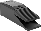
Wireless Foot Switches
Activate equipment from up to 40 feet away—these switches include a transmitter and a receiver that connects to equipment. The transmitter is rated IP68 and the receiver is rated IP01.
Wire Leads | Mounting | |||||||||||||
|---|---|---|---|---|---|---|---|---|---|---|---|---|---|---|
| No. of Circuits Controlled | Switch Starting Position | Switch Action | Industry Designation | Switching Current @ Voltage | Max. Voltage | Transmission Frequency, GHz | Color | No. of | Lg., ft. | Fasteners Included | No. of Holes | Hole Dia. | Each | |
1 Speed with Wire Leads | ||||||||||||||
Iron Housing with Aluminum Guard | ||||||||||||||
| 1 | 1 Off (Normally Open) or 1 On (Normally Closed) | Springs Back (Momentary) | SPDT | 10 A @ 125 V AC/250 V AC, 8 A @ 24 V DC | 48V DC 380V AC | 2.41-2.48 | Orange | 3 | 10 | No | 3 | 0.31" | 000000 | 000000000 |
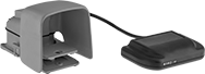
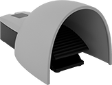
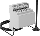
Wireless Self-Powered Foot Switches
Send signals to equipment up to 130 feet away. Because these foot switches are self-powered, they eliminate the clutter of wires and the fuss of batteries. Connect up to 40 switches to one receiver to set up an automation system that spans your whole facility.
These switches meet EN 60947-5-1, a European safety standard for switches.
Orange switches are easy to spot, reducing the risk you might trip on them.
![]() For technical drawings and 3-D models, click on a part number.
For technical drawings and 3-D models, click on a part number.
Actuator | |||||||||
|---|---|---|---|---|---|---|---|---|---|
| No. of Speeds | No. of Circuits Controlled | Max. Transmission Distance, ft. | Transmission Frequency, MHz | Color | Color | Material | Specifications Met | Each | |
Powder-Coated Aluminum Housing | |||||||||
| 1 | 1 | 130 | 915 | Blue | Black | Plastic | UL 94 V-0, EN 60947-5-1 | 0000000 | 0000000 |
| 1 | 1 | 130 | 915 | Orange | Blue | Powder-Coated Aluminum | EN 60947-5-1 | 0000000 | 000000 |
Powder-Coated Aluminum Housing with Aluminum Guard | |||||||||
| 1 | 1 | 130 | 915 | Orange | Orange | Powder-Coated Aluminum | EN 60947-5-1 | 0000000 | 000000 |
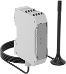
| No. of Circuits Controlled | Switch Starting Position | No. of Terminals | Max. Transmission Distance, ft. | Transmission Frequency, MHz | Industry Designation | Switching Current @ Voltage | Input Voltage | Max. Voltage | For DIN Rail Size | Specifications Met | Each | |
Screw Terminals—With LED Indicator and Antenna | ||||||||||||
|---|---|---|---|---|---|---|---|---|---|---|---|---|
| 4 | 4 Off (Normally Open) | 10 | 130 | 915 | SPST-NO | 3 A @ 250 V AC, 3 A @ 24 V DC | 24V DC | 250V AC | 35 mm | UL 94 V-0, EN 60947-5-1, CSA-US Certified, CSA Certified | 0000000 | 0000000 |
Spring-Clamp Terminals—With LED Indicator and Antenna | ||||||||||||
| 4 | 4 Off (Normally Open) or 4 On (Normally Closed) | 14 | 130 | 915 | SPDT | 6 A @ 250 V AC, 2 A @ 24 V DC | 24V AC 24V DC | 250V AC | 35 mm | CSA-US Certified, CSA Certified | 0000000 | 000000 |
Wireless Self-Powered 22 mm Panel-Mount Push-Button Switches
Mount these switches in panel cutouts where changing a battery or routing wires might be difficult—they power themselves when you push the button. These switches wirelessly send a signal to a receiver (sold separately) up to 330 feet away. Since they operate equipment without requiring wires back to your control panel, they’re often used for retrofit or temporary installations. The switches come in distinct colors to help operators quickly identify them.
Switches include enough contact blocks to control the number of circuits listed. Additional contact blocks (sold separately) can be added to control more circuits or replace the included contact block. Connect up to 32 contact blocks to one receiver.
![]() For technical drawings and 3-D models, click on a part number.
For technical drawings and 3-D models, click on a part number.

| No. of Circuits Controlled | Max. Transmission Distance, ft. | Transmission Frequency | Switch Action | Dia. | For Max. Panel Thick. | Dp. Behind Panel | For Max. Number of Contact Blocks | Choose an Actuator Color | Environmental Rating | Each | |
Plastic Base | |||||||||||
|---|---|---|---|---|---|---|---|---|---|---|---|
| 1 | 330 | 2,405 MHz | Springs Back (Momentary) | 1 1/8" | 1/4" | 1 5/8" | 3 | IP66, IP67, IP69K | 0000000 | 0000000 | |


| No. of Circuits Controlled | Switch Starting Position | Number of Terminals | Industry Designation | Switching Current @ Voltage | Input Voltage | Max. Voltage | Mounting Location | For DIN Rail Size | Ht. | Wd. | Dp. | Environmental Rating | Each | |
Screw Terminals | ||||||||||||||
|---|---|---|---|---|---|---|---|---|---|---|---|---|---|---|
| 2 | 2 Off (Normally Open) or 2 On (Normally Closed) | 6 | DPDT | 5 mA @ 250 V AC, 5 mA @ 250 V DC | 24V AC-240V AC/24V DC-240V DC | 250V AC/250V DC | DIN Rail | 35 mm | 4 1/4" | 2 13/16" | 1 7/16" | IP20 | 0000000 | 0000000 |
Smart Magnetic Contact Alarm Switches
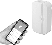
Use a free, downloadable app with these switches to automate alarms in your facility, such as sounding a buzzer if a trailer door is opened after a certain time. These switches link to your Wi-Fi network and push notifications to your smartphone. They have two parts: a magnet and a sensor. Mount each part to a surface—for instance, the magnet to a door and the sensor to the door frame—and the switch will send a signal when the magnet is pulled away.
![]() For technical drawings and 3-D models, click on a part number.
For technical drawings and 3-D models, click on a part number.
| Max. Sensing Distance | Operating System Compatibility | Lg. | Wd. | Ht. | Color | Batteries Included | Mounting Fasteners Included | Features | Specifications Met | Each | |
Plastic Housing | |||||||||||
|---|---|---|---|---|---|---|---|---|---|---|---|
Wi-Fi Connection | |||||||||||
| 0.5" | Android 6.0 or Later, iOS 11.0 or Later | 1.6" | 0.8" | 2.8" | White | Yes | Yes | Indicating Light | ETL Listed, C-ETL Listed | 0000000 | 000000 |
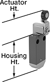
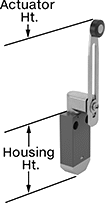
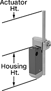
Wireless Self-Powered Limit Switches
Install these limit switches where changing a battery or routing wires might be difficult—they power themselves when a moving object contacts the actuator. Place them up to 330 ft. away from the receiver (sold separately). These switches have the rapid-closing action of a snap-acting switch, but with a larger actuator.
Plunger actuators open or close circuits when objects push against them.
Roller-plunger actuators open or close circuits when an object pushes against the roller, which moves the plunger. The roller moves parallel to the mounting direction, so it helps push the plunger even if the force isn’t straight on. The roller also reduces friction during actuation which prevents wear and tear over time.
Roller-lever actuators open or close circuits when material moves across the switch. The roller reduces friction during actuation which prevents wear and tear over time.
Rod actuators open or close circuits when material pushes against the rod. The rod extends from the body of the actuator, so these switches are ideal when objects actuating the switch are further away.
Use an antenna (sold separately) to increase the maximum transmission range to 984 ft. They also strengthen the signal if there are obstacles between your switch and receiver.
![]() For technical drawings and 3-D models, click on a part number.
For technical drawings and 3-D models, click on a part number.


Housing | ||||||||||||||
|---|---|---|---|---|---|---|---|---|---|---|---|---|---|---|
| No. of Circuits Controlled | Max. Transmission Distance, ft. | Transmission Frequency | Switch Action | Actuator Material | Operating Temp. Range, °F | Actuator Height | Lg. | Ht. | Dp. | Housing Material | Specifications Met | Each | ||
Plunger Actuator Style | ||||||||||||||
| A | 1 | 330 | 2,405 MHz | Springs Back (Momentary) | Zinc | -13° to 131° | 0.4" | 1.2" | 2 1/2" | 0.6" | Plastic | CE Marked, IEC 60947-5, EN 60947-5 | 0000000 | 0000000 |
Roller Plunger Actuator Style | ||||||||||||||
| B | 1 | 330 | 2,405 MHz | Springs Back (Momentary) | Steel | -13° to 131° | 0.8" | 1.2" | 2 1/2" | 0.6" | Plastic | CE Marked, IEC 60947-5, EN 60947-5 | 0000000 | 000000 |
Roller Lever Actuator Style | ||||||||||||||
| C | 1 | 330 | 2,405 MHz | Springs Back (Momentary) | Plastic | -13° to 131° | 1.7" | 1.2" | 2 1/2" | 0.6" | Plastic | CE Marked, IEC 60947-5, EN 60947-5 | 0000000 | 000000 |
| C | 1 | 330 | 2,405 MHz | Springs Back (Momentary) | Steel | -13° to 131° | 1.7" | 1.2" | 2 1/2" | 0.6" | Plastic | CE Marked, IEC 60947-5, EN 60947-5 | 0000000 | 000000 |
| D | 1 | 330 | 2,405 MHz | Springs Back (Momentary) | Plastic | -13° to 131° | 1.7"-3.6" | 1.2" | 2 1/2" | 0.6" | Plastic | CE Marked, IEC 60947-5, EN 60947-5 | 0000000 | 000000 |
| D | 1 | 330 | 2,405 MHz | Springs Back (Momentary) | Plastic | -13° to 131° | 2.5"-4.3" | 1.2" | 2 1/2" | 0.6" | Plastic | CE Marked, IEC 60947-5, EN 60947-5 | 0000000 | 000000 |
Rod Actuator Style | ||||||||||||||
| E | 1 | 330 | 2,405 MHz | Springs Back (Momentary) | Plastic | -13° to 131° | 3" | 1.2" | 2 1/2" | 0.6" | Plastic | CE Marked, IEC 60947-5, EN 60947-5 | 0000000 | 000000 |

| No. of Outputs | Max. Transmission Distance, ft. | Transmission Frequency | Max. Switching Current @ Voltage | Input Voltage | Signal Output Type | Mounting Location | For DIN Rail Size | Wd. | Ht. | Dp. | Environmental Rating | Specifications Met | Each | |
With Screw Terminals | ||||||||||||||
|---|---|---|---|---|---|---|---|---|---|---|---|---|---|---|
| 2 | 330 | 2,405 MHz | 200 mA @ 24 V DC | 24V DC | PNP | DIN Rail | 35 mm | 1 7/16" | 4 1/4" | 2 15/16" | IP20 | CE Marked, IEC 60947-1, IEC 60947-5-1, EN 60947-5-1, EN 60947-1 | 0000000 | 0000000 |
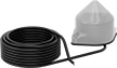
| Max. Transmission Distance, ft. | Transmission Frequency | Input Voltage | Cable Lg., ft. | Environmental Rating | Specifications Met | Each | |
With Wire Leads | |||||||
|---|---|---|---|---|---|---|---|
| 984 | 2,405 MHz | 24V AC-240V AC, 24V DC-240V DC | 16 | IP65 | UL Listed, CSA Certified, CE Marked | 0000000 | 0000000 |
Wireless Enclosed Relays
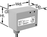
Send a signal to turn equipment on and off from up to 150 feet away without having to run electrical wire. These relays have an enclosure to protect the terminals from dust and accidental bumps. They can be set to transmit, receive, or both at once. You’ll need at least two relays to switch a device. They have an alarm that can be set to check for certain conditions before transmitting a signal. For example, you could set these relays to send a signal to turn on an air conditioner if all windows are closed. The repeat function extends the transmitting signal through a maximum of two receiving relays.
Relays that are set to transmit can be linked up to as many receiving relays as you need. Relays set to receive can be linked up to 30 transmitting relays. All relays connect to dry contacts on your switch, sensor, or controller. Use the wire leads to connect them to a power source.
UL and C-UL listed, all meet American and Canadian safety standards. Rated NEMA 1, they should only be used indoors.
![]() For technical drawings and 3-D models, click on a part number.
For technical drawings and 3-D models, click on a part number.
Wire Lead | Conduit Connection | |||||||||||||||
|---|---|---|---|---|---|---|---|---|---|---|---|---|---|---|---|---|
| Input Voltage | Control Current | Switching Current @ 277V AC | Maximum Switching Voltage | hp @ Switching Voltage | Ht. | Wd. | Dp. | Maximum Transmission Distance, ft. | Lg. | Number of | Gender | Trade Size | Thread Type | Environmental Rating | Each | |
1 Circuit Controlled with 1 Off (Normally Open) or 1 On (Normally Closed)—SPDT | ||||||||||||||||
| 120V AC | 73 | 20A | 277V AC | 2 hp @ 277 V AC | 2.3" | 3.2" | 1.8" | 150 | 16" | 7 | Male | 1/2 | NPT | NEMA 1 | 0000000 | 0000000 |
| 208V AC | 80 | 20A | 277V AC | 2 hp @ 277 V AC | 2.3" | 3.2" | 1.8" | 150 | 16" | 7 | Male | 1/2 | NPT | NEMA 1 | 0000000 | 000000 |
| 240V AC | 80 | 20A | 277V AC | 2 hp @ 277 V AC | 2.3" | 3.2" | 1.8" | 150 | 16" | 7 | Male | 1/2 | NPT | NEMA 1 | 0000000 | 000000 |
| 277V AC | 80 | 20A | 277V AC | 2 hp @ 277 V AC | 2.3" | 3.2" | 1.8" | 150 | 16" | 7 | Male | 1/2 | NPT | NEMA 1 | 0000000 | 000000 |
| 24V AC, 24V DC | 69 | 20A | 277V AC | 2 hp @ 277 V AC | 2.3" | 3.2" | 1.8" | 150 | 16" | 7 | Male | 1/2 | NPT | NEMA 1 | 0000000 | 000000 |
Smart DIN-Rail Mount Multifunction Timer Relays
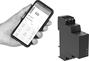
Whether installed in an electrical cabinet or hard-to-reach area, these timer relays are controlled remotely from your smartphone. They connect to your phone via a free downloadable app with NFC (Near Field Communication), so you can set time delay ranges, adjust settings, and save programs. An LED indicator on the relay shows that your switch is on and whether it’s actuated. Mount them directly to 35 mm DIN rail (also known as DIN 3 rail).
Although these relays have 30 different functions, they all fall into 11 categories. Within these categories, you can select different functions to allow you to add a switch, program a delay, or change how the relay responds to a trigger (turning on or off, pausing, or resetting).
Manual Switch Control—Use these functions to turn the relay on and off with a switch.
Fixed On/Off—The on function keeps the relay on whenever input voltage is applied; it will only turn off if the voltage is removed. The off function keeps the relay in an off state, even if input voltage is applied.
Switch-On (Single-Shot)—These functions require a switch to activate the relay, which stays on for the programmed amount of time. For example, lights in a storage room are turned on with a switch and stay on for a set time before turning off.
Delayed Start (Delay-on-Make)—These functions allow you to set how long it takes for the relay to turn on after input voltage is applied. For example, a drill starts pumping lubricant immediately, but it does not start rotating until the set time has elapsed.
Delayed Switch-Off (Delay-on-Break)—These functions use a switch instead of input voltage. When the switch is turned off, the relay remains on for a programmed amount of time before turning off. For example, a projector’s light is turned off with a switch, but its cooling fan continues to run for a set time.
Delayed Switch-On with Delayed Switch-Off—This function uses a switch instead of an input voltage. It allows you to set how long it takes the relay to turn on after a switch is turned on, and how long it will stay on after the switch is turned off. For example, a furnace turns on, but the fan doesn’t start pushing air through the vents until it has been heated. When the furnace turns off, the fan keeps blowing to circulate all the hot air.
Interval—These functions use input voltage to turn on the relay for a programmed amount of time. For example, when a part moving down a conveyor reaches a certain location, a cleaning spray comes on for a set amount of time.
Repeat Cycle—These functions start with an on cycle and then alternate between an on cycle and off cycle of equal durations until input voltage is removed, such as with a flashing light.
Asymmetrical Repeat Cycle—These functions start with an on-cycle and then have an off-cycle, but these cycles have different durations. The cycles repeat until input voltage is removed. For example, a sprinkler system sprays in short bursts followed by longer rest periods, on and off until input voltage is removed.
Switch-On Asymmetrical Repeat Cycle—These functions require a switch to activate the timing function. The input voltage is applied the whole time, and when you turn the switch on, the relay begins with an on-cycle followed by an off-cycle. These cycles have different durations, and they repeat until you turn the switch off. They could be used to turn on a motor or other system for a short period and then turn it off for a longer rest period, repeating that pattern until the switch is turned off.
Star-to-Delta—These functions allow you to set the time delay within the relay's range to switch contacts on a three-phase motor from star to delta configuration. Since star configuration takes less voltage to start than delta, these functions prevent voltage dips that often happen when a motor starts and are gentler on mechanical parts.
![]() For technical drawings and 3-D models, click on a part number.
For technical drawings and 3-D models, click on a part number.
| No. of Terminals | Input Voltage | Control Power, W | Timer Relay Function | O'all Timing Range | Switching Current @ 240V AC | Max. Switching Voltage | Ht. | Wd. | Dp. | Operating System Compatibility | Features | Each | |
1 Circuit Controlled with 1 Off (Normally Open) or 1 On (Normally Closed)—SPDT | |||||||||||||
|---|---|---|---|---|---|---|---|---|---|---|---|---|---|
| 8 | 12V AC, 24V AC, 48V AC, 120V AC, 240V AC, 12V DC, 24V DC, 48V DC, 60V DC, 120V DC, 240V DC | 0.15 | Manual Switch Control Fixed On/Off Switch-On (Single-Shot) Delayed Start (Delay-on-Make) Delayed Switch-Off (Delay-on-Break) Delayed Switch-On with Delayed Switch-Off Interval Repeat Cycle Asymmetrical Repeat Cycle Switch-On Asymmetrical Repeat Cycle | 0.1 sec.-999 days | 8A | 250V AC | 4.1" | 0.7" | 2.5" | Android 5.0 or Later, iOS 14.4 or Later | LED Indicator | 0000000 | 000000 |
2 Circuits Controlled with 2 Off (Normally Open) or 2 On (Normally Closed)—DPDT | |||||||||||||
| 9 | 24V AC, 48V AC, 120V AC, 240V AC, 24V DC, 48V DC, 60V DC, 120V DC, 240V DC | 0.6 | Manual Switch Control Fixed On/Off Switch-On (Single-Shot) Delayed Start (Delay-on-Make) Delayed Switch-Off (Delay-on-Break) Delayed Switch-On with Delayed Switch-Off Interval Repeat Cycle Asymmetrical Repeat Cycle Switch-On Asymmetrical Repeat Cycle Star-to-Delta | 0.1 sec.-999 hrs. | 8A | 250V AC | 3.5" | 0.9" | 2.9" | Android 4.4 or Later, iOS 14.5 or Later | LED Indicator | 0000000 | 00000 |