


Choosing an Electrical Switch
More
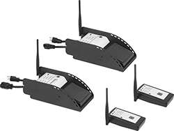
Wireless Foot Switches
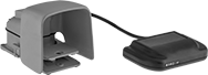
Activate equipment from up to 40 feet away—these switches include a transmitter and a receiver that connects to equipment. The transmitter is rated IP68 and the receiver is rated IP01.
Wire Leads | Mounting | |||||||||||||
|---|---|---|---|---|---|---|---|---|---|---|---|---|---|---|
| No. of Circuits Controlled | Switch Starting Position | Switch Action | Industry Designation | Switching Current @ Voltage | Max. Voltage | Transmission Frequency, GHz | Color | No. of | Lg., ft. | Fasteners Included | No. of Holes | Hole Dia. | Each | |
1 Speed with Wire Leads | ||||||||||||||
Iron Housing with Aluminum Guard | ||||||||||||||
| 1 | 1 Off (Normally Open) or 1 On (Normally Closed) | Springs Back (Momentary) | SPDT | 10 A @ 125 V AC/250 V AC, 8 A @ 24 V DC | 48V DC 380V AC | 2.41-2.48 | Orange | 3 | 10 | No | 3 | 0.31" | 000000 | 000000000 |
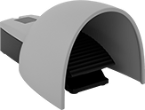
Wireless Self-Powered Foot Switches
Send signals to equipment up to 130 feet away. Because these foot switches are self-powered, they eliminate the clutter of wires and the fuss of batteries. Connect up to 40 switches to one receiver to set up an automation system that spans your whole facility.
These switches meet EN 60947-5-1, a European safety standard for switches.
Orange switches are easy to spot, reducing the risk you might trip on them.
![]() For technical drawings and 3-D models, click on a part number.
For technical drawings and 3-D models, click on a part number.

Actuator | |||||||||
|---|---|---|---|---|---|---|---|---|---|
| No. of Speeds | No. of Circuits Controlled | Max. Transmission Distance, ft. | Transmission Frequency, MHz | Color | Color | Material | Specifications Met | Each | |
Powder-Coated Aluminum Housing | |||||||||
| 1 | 1 | 130 | 915 | Blue | Black | Plastic | UL 94 V-0, EN 60947-5-1 | 0000000 | 0000000 |
| 1 | 1 | 130 | 915 | Orange | Blue | Powder-Coated Aluminum | EN 60947-5-1 | 0000000 | 000000 |
Powder-Coated Aluminum Housing with Aluminum Guard | |||||||||
| 1 | 1 | 130 | 915 | Orange | Orange | Powder-Coated Aluminum | EN 60947-5-1 | 0000000 | 000000 |
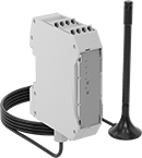
| No. of Circuits Controlled | Switch Starting Position | No. of Terminals | Max. Transmission Distance, ft. | Transmission Frequency, MHz | Industry Designation | Switching Current @ Voltage | Input Voltage | Max. Voltage | For DIN Rail Size | Specifications Met | Each | |
Screw Terminals—With LED Indicator and Antenna | ||||||||||||
|---|---|---|---|---|---|---|---|---|---|---|---|---|
| 4 | 4 Off (Normally Open) | 10 | 130 | 915 | SPST-NO | 3 A @ 250 V AC, 3 A @ 24 V DC | 24V DC | 250V AC | 35 mm | UL 94 V-0, EN 60947-5-1, CSA-US Certified, CSA Certified | 0000000 | 0000000 |
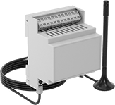
Spring-Clamp Terminals—With LED Indicator and Antenna | ||||||||||||
| 4 | 4 Off (Normally Open) or 4 On (Normally Closed) | 14 | 130 | 915 | SPDT | 6 A @ 250 V AC, 2 A @ 24 V DC | 24V AC 24V DC | 250V AC | 35 mm | CSA-US Certified, CSA Certified | 0000000 | 000000 |
Dual-Operator Safety Switches
To prevent accidents, these switches won’t let your machine start running unless two people in different locations coordinate control. This is useful for large operations where it would be difficult to hear or see someone call for power to be cut. They come with two foot switches that communicate wirelessly—both need to be pressed at the same time for your machine to run. For example, if used with a machine that pulls wire up a building through conduit, this means that two people dozens of floors apart can each stop the machine by releasing their foot. As an extra precaution, give the included pendant switches to people walking around your operation. If they see a problem, the pendant switches shut power off with a push of a button, even if the foot switches are pressed.
The foot switches work up to 3.7 miles away from each other if there’s a clear line of sight between the two. If there are walls or other obstacles, they work up to 1,500 ft. away from each other. Plug your equipment into the receiver foot switch before plugging the switch into an outlet—no wiring is required.
| No. of Circuits Controlled | Switch Starting Position | Switch Action | Industry Designation | Switching Current @ Voltage | Max. Transmission Distance, mi | Ht. | Wd. | Dp. | Environmental Rating | Includes | Each | |
Aluminum Housing with Amperage Draw Gauge and LED Status Indicator | ||||||||||||
|---|---|---|---|---|---|---|---|---|---|---|---|---|
NEMA 5-20 Plug × NEMA 5-20 Socket | ||||||||||||
| 1 | 1 Off (Normally Open) | Springs Back (Momentary) | SPST-NO | 20 A @ 120 V AC | 3.7 | 4 1/4" | 6 1/4" | 12 1/4" | IP55 | Receiver Foot Switch, Transmitter Foot Switch, Two Wireless Pendant Switches, Carrying Case, NEMA 5-15 Plug Adapter, Turn-Lock Plug Adapter, Two Battery Chargers | 0000000 | 000000000 |