About Pipe Size
More
About Pressure Gauges
More
Corner Weld Inspection Gauges

Also known as a fillet gauge, this gauge measures concave and convex corner weld dimensions.
| Radius Measured | Metric Radius Measured, mm | Measures | Material | Includes | Each | |
MIG, TIG, Stick, Oxyacetylene Welding Process | ||||||
|---|---|---|---|---|---|---|
| 1/8", 3/16", 1/4", 5/16", 3/8", 7/16", 1/2", 5/8", 3/4", 7/8", 1" | 3, 5, 6, 8, 10, 11, 13, 16, 19, 22, 25 | Concave Corners, Convex Corners | Steel | Vinyl Carrying Case | 0000000 | 000000 |
Multicheck Weld Inspection Gauges

Check bevel angles, excess weld metal (capping size), length of a corner-weld leg, throat length, and depth of undercut.
Excess Weld Metal (Capping Size) | Corner-Weld Leg Lg. | Throat Lg. | Dp. of Undercut | |||||||||
|---|---|---|---|---|---|---|---|---|---|---|---|---|
| Bevel Angle Measured | Max. Size Measured | Graduation Marks | Max. Lg. Measured | Graduation Marks | Max. Lg. Measured | Graduation Marks | Max. Size Measured | Graduation Marks | Material | Includes | Each | |
MIG, TIG, Stick, Oxyacetylene Welding Process | ||||||||||||
| 0°-60° | 1", 25 mm | 1/16", 1 mm | 1", 25mm | 1/16", 1 mm | 3/4", 20mm | 1/16", 1 mm | 3/16", 5 mm | 1/16", 1 mm | Stainless Steel | Vinyl Carrying Case | 0000000 | 0000000 |
Weld Alignment Inspection Gauges

Measure internal misalignment of pipe ID, pipe wall thickness after tack welding, and go/no-go fit-up gap.
Internal Misalignment of Pipe ID | Pipe Wall Thick. After Tack Welding | ||||||
|---|---|---|---|---|---|---|---|
| Max. Size Measured | Graduation Marks | Max. Thick. Measured | Graduation Marks | Go/No-Go Fit-Up Gap Size Measured Range | Material | Each | |
MIG, TIG, Stick, Oxyacetylene Welding Process | |||||||
| 1/16", 30 mm | 1/32", 1 mm | 1 3/4", 45mm | 1/16", 1 mm | 1/16"-3/32" | Stainless Steel | 0000000 | 0000000 |
Gas Pressure Gauges


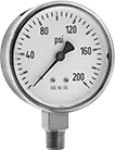
Use these gauges with pumps, filters, regulators, and in process lines to monitor the pressure of compressed gas. Mount them with the dial face upright. Gauges for use with acetylene can also be used in welding applications.
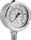
Gauges with brass case are cleaned to meet ASME B40.1, Level IV for oxygen service.
Gauges with 304 stainless steel case are cleaned and bagged to meet ASME B40.1, Level IV for oxygen service.
For technical drawings and 3-D models, click on a part number.
- For Use With: Air, Acetylene, Carbon Dioxide, and Oxygen
- Accuracy: ±2% Mid Scale (Grade B)
Available Pressure Ranges | ||
|---|---|---|
| Pressure Range, psi | Graduation Marks, psi | Numeric Increments, psi |
| 0 to 30 | 1 | 5 |
| 0 to 60 | 1 | 10 |
| 0 to 100 | 2 | 20 |
| 0 to 200 | 5 | 40 |
| 0 to 400 | 10 | 50 |
| 0 to 600 | 10 | 100 |
| 0 to 1,000 | 20 | 200 |
| 0 to 2,000 | 50 | 400 |
| 0 to 3,000 | 50 | 500 |
| 0 to 4,000 | 100 | 500 |
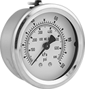
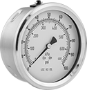
- For Use With: Oxygen
- Accuracy: ±1% Mid Scale (Grade A); except
4" Dial Dia.: ±1% Full Scale (Grade 1A)
Available Pressure Ranges | |||||||||
|---|---|---|---|---|---|---|---|---|---|
Bottom and Center Back Connections | Lower Back Connection | ||||||||
Pressure Range | Graduation Marks | Numeric Increments | Graduation Marks | Numeric Increments | |||||
| psi | kPa | psi | kPa | psi | kPa | psi | kPa | psi | kPa |
2 1/2" Dial Diameter | |||||||||
| 0 to 15 | 0 to 102 | 0.2 | 2 | 3 | 20 | __ | __ | __ | __ |
| 0 to 30 | 0 to 205 | 0.5 | 5 | 5 | 50 | __ | __ | __ | __ |
| 0 to 100 | 0 to 680 | 2 | 10 | 20 | 100 | __ | __ | __ | __ |
| 0 to 200 | 0 to 1,350 | 5 | 50 | 50 | 200 | __ | __ | __ | __ |
| 0 to 300 | 0 to 2,050 | 5 | 50 | 50 | 500 | __ | __ | __ | __ |
| 0 to 600 | 0 to 4,100 | 10 | 100 | 100 | 1,000 | __ | __ | __ | __ |
4" Dial Diameter | |||||||||
| 0 to 15 | 0 to 103 | 0.2 | 1 | 3 | 10 | 0.2 | 1 | 3 | 10 |
| 0 to 30 | 0 to 206 | 0.5 | 2 | 5 | 20 | 0.5 | 2 | 5 | 20 |
| 0 to 100 | 0 to 680 | 1 | 10 | 10 | 100 | 1 | 10 | 10 | 100 |
| 0 to 200 | 0 to 1,360 | 2 | 20 | 20 | 200 | 2 | 20 | 20 | 200 |
| 0 to 300 | 0 to 2,060 | 5 | 20 | 50 | 200 | 5 | 20 | 50 | 200 |
| 0 to 600 | 0 to 4,100 | 10 | 50 | 100 | 500 | 10 | 100 | 100 | 1,000 |
| Dial Diameter | Pipe Size | Environment Temp. Range, °F | Process Temp. Range, °F | Mounting Orientation | Each | |
Bottom Connection | ||||||
|---|---|---|---|---|---|---|
NPT Male | ||||||
| 2 1/2" | 1/4 | -40° to 140° | -40° to 140° | Upright | 0000000 | 000000 |
| 4" | 1/4 | -40° to 140° | -40° to 140° | Upright | 0000000 | 00000 |
Center Back Connection | ||||||
NPT Male | ||||||
| 2 1/2" | 1/4 | -40° to 140° | -40° to 140° | Upright | 0000000 | 00000 |
Lower Back Connection | ||||||
NPT Male | ||||||
| 4" | 1/4 | -40° to 140° | -40° to 140° | Upright | 0000000 | 00000 |


