


Spring Clamps


Squeeze the handles to open the clamp; release and the spring holds it tightly in place. Clamping surfaces are parallel when fully opened.
Stainless steel and fiberglass clamps have excellent corrosion resistance.
Cushion-grip clamps have plastic-covered handles for a comfortable grip.
![]() For technical drawings and 3-D models, click on a part number.
For technical drawings and 3-D models, click on a part number.
Opening | Jaw | ||||||||
|---|---|---|---|---|---|---|---|---|---|
| Max. | Min. | Reach | Holding Capacity, lbs. | Type | Wd. | Material | Overall Lg. | Each | |
Steel Body | |||||||||
Plain Grip | |||||||||
| 1" | 0" | 1 1/4" | 36 1/2 | Fixed | 3/4" | Steel | 4" | 000000 | 00000 |
| 2" | 0" | 2" | 55 | Fixed | 1" | Steel | 6" | 000000 | 0000 |
| 3" | 0" | 3" | 64 | Fixed | 1 1/4" | Steel | 9" | 000000 | 0000 |
| 4" | 0" | 4" | 89 | Fixed | 1 1/4" | Steel | 12" | 000000 | 00000 |
Cushion Grip | |||||||||
| 1" | 0" | 1 1/4" | 36 1/2 | Fixed | 3/4" | PVC Plastic | 4" | 000000 | 0000 |
| 2" | 0" | 2" | 55 | Fixed | 1" | PVC Plastic | 6" | 000000 | 0000 |
| 3" | 0" | 3" | 64 | Fixed | 1 1/4" | PVC Plastic | 9" | 0000000 | 00000 |
| 4" | 0" | 4" | 89 | Fixed | 1 1/4" | PVC Plastic | 12" | 0000000 | 00000 |
Plastic Body | |||||||||
Plain Grip | |||||||||
| 3/4" | 0" | 1 1/2" | 5 | Pivoting | 3/8" | Polypropylene Plastic | 3 1/4" | 00000000 | 0000 |
| 1" | 0" | 1 1/2" | Not Rated | Pivoting | 1" | Thermoplastic Plastic | 4 1/2" | 00000000 | 0000 |
| 2" | 0" | 2 5/8" | Not Rated | Pivoting | 1 1/8" | Thermoplastic Plastic | 6 1/4" | 00000000 | 0000 |
| 3" | 0" | 3 3/4" | Not Rated | Pivoting | 1 1/8" | Thermoplastic Plastic | 8 3/4" | 00000000 | 0000 |
316 Stainless Steel Body | |||||||||
Cushion Grip | |||||||||
| 2 1/4" | 0" | 2 1/8" | 35 | Fixed | 1 1/4" | 316 Stainless Steel | 6" | 0000000 | 00000 |
| 2 1/4" | 0" | 2 1/8" | 45 | Fixed | 1 1/4" | 316 Stainless Steel | 6" | 0000000 | 00000 |
Fiberglass | |||||||||
Plain Grip | |||||||||
| 2 1/2" | 1" | 2 3/4" | 60 | Fixed | 5/8" | Fiberglass | 8 1/4" | 0000000 | 00000 |
Miniature Spring Clamps


Clamp thin materials and in tight spaces. Squeeze the handles to open the clamp; release and the spring holds it tightly in place. Clamps with a hole on the end can be secured to your workholder’s arm, so your hands are free for soldering, gluing, and assembling.
Style A clamps have alligator-grip jaws to hold material securely.
Style D clamps have a plate built into their jaws that lets them apply pressure evenly, without denting or marring what they hold. Use these clamps with ceramics, plastics, and other sensitive materials.
Style E clamps have a support beam that keeps them upright and balanced. They can hold material for a long time without adding extra pressure.
Style F, G, H, J, and L clamps have a long bottom jaw for supporting large material or thin sheets and bars.
Style M clamps have jaws with three sections: a point for precise contact, a flat area for general gripping, and a curved portion for holding round material.
Steel clamps are medium weight and good for holding light materials. Since steel isn’t a good heat conductor, these clamps won’t work well as a heat sink.
Stainless steel clamps resist high temperatures, so you can use them as a heat sink. These clamps are good for soldering because solder won’t stick to them. 17-7 PH stainless steel clamps have a 700° F maximum temperature for use in electroplating applications.
Aluminum clamps are lightweight. They also conduct heat and electricity, so you can use them as a heat sink.
Clamps with a cushion grip are comfortable to hold.
Clamps with a plain grip have an all-metal construction that makes them good for holding parts while soldering. Style A and B clamps have a textured handle that helps you get a better grip.
![]() For technical drawings and 3-D models, click on a part number.
For technical drawings and 3-D models, click on a part number.
Opening | Jaw | |||||||||
|---|---|---|---|---|---|---|---|---|---|---|
| Style | Max. | Min. | Reach | Holding Capacity, lbs. | Wd. | Material | Overall Lg. | Max. Temperature, °F | Each | |
18-8 Stainless Steel Body | ||||||||||
Plain Grip | ||||||||||
| A | 3/8" | 0" | 1/2" | Not Rated | 1/2" | 18-8 Stainless Steel | 1 1/2" | Not Rated | 0000000 | 00000 |
| B | 5/16" | 0" | 1/2" | Not Rated | 1/2" | 18-8 Stainless Steel | 1 5/8" | Not Rated | 0000000 | 0000 |
17-7 PH Stainless Steel Body | ||||||||||
Plain Grip | ||||||||||
| C | 9/16" | 0" | 1 1/4" | 1 1/2 | 3/8" | 17-7 PH Stainless Steel | 3" | 700° | 000000 | 00000 |
| D | 5/16" | 0" | 1 1/4" | 1 1/2 | 3/8" | 17-7 PH Stainless Steel | 3" | 700° | 0000000 | 00000 |
| E | 5/16" | 0" | 1 1/4" | 1 1/2 | 3/8" | 17-7 PH Stainless Steel | 3" | 700° | 0000000 | 00000 |
| F | 5/16" | 0" | 1 1/8" | 1 1/2 | 1/8" | 17-7 PH Stainless Steel | 2 3/8" | 700° | 0000000 | 00000 |
| F | 5/8" | 0" | 1 1/2" | 1 1/2 | 3/8" | 17-7 PH Stainless Steel | 3 1/4" | 700° | 000000 | 00000 |
| F | 11/16" | 0" | 1" | 1 1/2 | 1/4" | 17-7 PH Stainless Steel | 2 3/8" | 700° | 000000 | 00000 |
| F | 3/4" | 0" | 3/4" | 1 1/2 | 5/32" | 17-7 PH Stainless Steel | 1 5/8" | 700° | 000000 | 00000 |
| G | 5/16" | 0" | 1 1/2" | 1 1/2 | 3/8" | 17-7 PH Stainless Steel | 3 1/4" | 700° | 0000000 | 00000 |
| H | 5/16" | 0" | 1 9/16" | 1 1/2 | 3/8" | 17-7 PH Stainless Steel | 3 3/8" | 700° | 0000000 | 00000 |
| J | 5/16" | 0" | 1 1/8" | 1 1/2 | 1/4" | 17-7 PH Stainless Steel | 2 3/8" | 700° | 0000000 | 00000 |
| K | 5/16" | 0" | 1 1/8" | 1 1/2 | 1/4" | 17-7 PH Stainless Steel | 2 3/8" | 700° | 0000000 | 00000 |
| L | 5/16" | 0" | 1 1/8" | 1 1/2 | 1/4" | 17-7 PH Stainless Steel | 2 3/8" | 700° | 0000000 | 00000 |
Aluminum Body | ||||||||||
Plain Grip | ||||||||||
| M | 1/4" | 0" | 3/16" | Not Rated | 1/16" | Aluminum | 2 1/2" | Not Rated | 0000000 | 0000 |
Steel Body | ||||||||||
Plain Grip | ||||||||||
| N | 1/4" | 0" | 7/8" | Not Rated | 5/16" | Steel | 2 1/4" | Not Rated | 0000000 | 0000 |
Cushion Grip | ||||||||||
| P | 3/16" | 0" | 7/16" | Not Rated | 3/16" | Steel | 1 3/8" | Not Rated | 0000000 | 0000 |
Extended-Reach Spring Clamps

The long, narrow jaws clamp farther into a workpiece and in tight spots. Squeeze the handles to open the clamp; release and the spring holds it tightly in place. Clamps have plastic-covered handles for a comfortable grip. Clamping surfaces are parallel when fully opened.
![]() For technical drawings and 3-D models, click on a part number.
For technical drawings and 3-D models, click on a part number.
Opening | Jaw | |||||||
|---|---|---|---|---|---|---|---|---|
| Max. | Min. | Reach | Holding Capacity | Wd. | Material | Overall Lg. | Each | |
Plastic Body | ||||||||
| 3" | 0" | 4" | Not Rated | 7/16" | Nylon Plastic | 8 3/4" | 0000000 | 00000 |
Adjustable-Jaw Spring Clamps


Hold large workpieces with a standard-size clamp. Slide the jaws to adjust the opening size. Squeeze the handles to open the clamp; release and the spring holds it tightly in place. Clamps have plastic-covered handles for a comfortable grip. Clamping surfaces are parallel when fully opened.
![]() For technical drawings and 3-D models, click on a part number.
For technical drawings and 3-D models, click on a part number.
Spring Clamps with Flexible Arm


Attached to an arm you can flex into position, these clamps hold objects such as a flashlight, tool, or instructions. Squeeze the handles to open the clamp; release and the spring holds it tightly in place.
Magnetic-mount clamp attaches to steel surfaces.
![]() For technical drawings and 3-D models, click on a part number.
For technical drawings and 3-D models, click on a part number.
Spring Clamps with Telescoping Handle

Extend the handle to reach the clamp into tight spaces. Squeeze the handles to open the clamp; release and the spring holds it tightly in place.
![]() For technical drawings and 3-D models, click on a part number.
For technical drawings and 3-D models, click on a part number.
Opening | Jaw | |||||||
|---|---|---|---|---|---|---|---|---|
| Max. | Min. | Reach | Holding Capacity | Wd. | Material | Overall Lg. | Each | |
Chrome-Plated Steel Body | ||||||||
| 1/2" | 0" | 11/16" | Not Rated | 1/2" | Chrome-Plated Steel | 6 1/4"-24 1/2" | 0000000 | 000000 |
Clothespins and Spring Clips

Hold lightweight objects, secure covers, and seal bags.
| Material | Lg. | Wd. | Pkg. Qty. | Pkg. | |
| Wood | 3 1/4" | 3/8" | 24 | 00000000 | 00000 |
Dual-Clamping Fixture Clamps
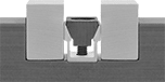
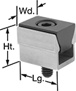
Set one of these clamps between two workpieces in a fixture and tighten the screw to push the clamp's sides out for a secure hold. The minimal contact leaves more of the workpieces free for machining.
![]() For technical drawings and 3-D models, click on a part number.
For technical drawings and 3-D models, click on a part number.
Thread | Drive | |||||||||||
|---|---|---|---|---|---|---|---|---|---|---|---|---|
| Lg. | Wd. | Ht. | Max. Clamping Force, lbs. | Size | Lg. | Size | Style | Material | Screw Material | Wedge Material | Each | |
| 5/16" | 1/4" | 17/64" | 200 | 2-56 | 3/8" | 5/64" | Hex | Aluminum | Steel | Steel | 0000000 | 000000 |
| 15/32" | 3/8" | 3/8" | 300 | 4-40 | 1/2" | 3/32" | Hex | Aluminum | Steel | Steel | 0000000 | 00000 |
| 5/8" | 1/2" | 37/64" | 500 | 8-32 | 5/8" | 9/64" | Hex | Aluminum | Steel | Steel | 0000000 | 00000 |
| 15/16" | 3/4" | 49/64" | 1,500 | 1/4"-20 | 7/8" | 3/16" | Hex | Aluminum | Steel | Steel | 0000000 | 00000 |
| 1 1/4" | 1" | 1 1/64" | 2,000 | 5/16"-18 | 1 1/4" | 1/4" | Hex | Aluminum | Steel | Steel | 0000000 | 00000 |
| 1 7/8" | 1 1/2" | 1 33/64" | 3,500 | 1/2"-13 | 2" | 3/8" | Hex | Aluminum | Steel | Steel | 0000000 | 00000 |
| 2 1/2" | 2" | 2 1/32" | 6,000 | 5/8"-11 | 2 1/2" | 1/2" | Hex | Aluminum | Steel | Steel | 0000000 | 00000 |
Thread | Drive | ||||||||||||
|---|---|---|---|---|---|---|---|---|---|---|---|---|---|
| Lg. | Wd. | Ht. | Max. Clamping Force, lbs. | Size | Lg. | Size | Style | Material | Screw Material | Wedge Material | Pkg. Qty. | Pkg. | |
| 5/16" | 1/4" | 17/64" | 200 | 2-56 | 3/8" | 5/64" | Hex | Aluminum | Steel | Steel | 6 | 0000000 | 000000 |
| 15/32" | 3/8" | 3/8" | 300 | 4-40 | 1/2" | 3/32" | Hex | Aluminum | Steel | Steel | 6 | 0000000 | 00000 |
| 5/8" | 1/2" | 37/64" | 500 | 8-32 | 5/8" | 9/64" | Hex | Aluminum | Steel | Steel | 8 | 0000000 | 00000 |
| 15/16" | 3/4" | 49/64" | 1,500 | 1/4"-20 | 7/8" | 3/16" | Hex | Aluminum | Steel | Steel | 6 | 0000000 | 00000 |
| 1 1/4" | 1" | 1 1/64" | 2,000 | 5/16"-18 | 1 1/4" | 1/4" | Hex | Aluminum | Steel | Steel | 4 | 0000000 | 00000 |
| 1 7/8" | 1 1/2" | 1 33/64" | 3,500 | 1/2"-13 | 2" | 3/8" | Hex | Aluminum | Steel | Steel | 2 | 0000000 | 000000 |
| 2 1/2" | 2" | 2 1/32" | 6,000 | 5/8"-11 | 2 1/2" | 1/2" | Hex | Aluminum | Steel | Steel | 2 | 0000000 | 000000 |
Thread | Drive | ||||||||||||
|---|---|---|---|---|---|---|---|---|---|---|---|---|---|
| Lg., mm | Wd., mm | Ht., mm | Max. Clamping Force, lbs. | Size | Pitch, mm | Lg., mm | Size | Style | Material | Screw Material | Wedge Material | Each | |
| 8.1 | 6.4 | 6.9 | 195 | M2 | 0.4 | 10 | 1.5 mm | Hex | Aluminum | Steel | Steel | 0000000 | 000000 |
| 11.9 | 9.5 | 9.7 | 300 | M2.5 | 0.45 | 12 | 2 mm | Hex | Aluminum | Steel | Steel | 0000000 | 00000 |
| 15.9 | 12.7 | 14.5 | 500 | M4 | 0.7 | 16 | 3 mm | Hex | Aluminum | Steel | Steel | 0000000 | 00000 |
| 23.8 | 19 | 19 | 1,500 | M6 | 1 | 25 | 5 mm | Hex | Aluminum | Steel | Steel | 0000000 | 00000 |
| 31.7 | 25.4 | 25.9 | 2,500 | M8 | 1.25 | 30 | 6 mm | Hex | Aluminum | Steel | Steel | 0000000 | 00000 |
Thread | Drive | |||||||||||||
|---|---|---|---|---|---|---|---|---|---|---|---|---|---|---|
| Lg., mm | Wd., mm | Ht., mm | Max. Clamping Force, lbs. | Size | Pitch, mm | Lg., mm | Size | Style | Material | Screw Material | Wedge Material | Pkg. Qty. | Pkg. | |
| 8.1 | 6.4 | 6.9 | 195 | M2 | 0.4 | 10 | 1.5 mm | Hex | Aluminum | Steel | Steel | 6 | 0000000 | 000000 |
| 11.9 | 9.5 | 9.7 | 300 | M2.5 | 0.45 | 12 | 2 mm | Hex | Aluminum | Steel | Steel | 6 | 0000000 | 00000 |
| 15.9 | 12.7 | 14.5 | 500 | M4 | 0.7 | 16 | 3 mm | Hex | Aluminum | Steel | Steel | 8 | 0000000 | 00000 |
| 23.8 | 19 | 19 | 1,500 | M6 | 1 | 25 | 5 mm | Hex | Aluminum | Steel | Steel | 6 | 0000000 | 00000 |
| 31.7 | 25.4 | 25.9 | 2,500 | M8 | 1.25 | 30 | 6 mm | Hex | Aluminum | Steel | Steel | 4 | 0000000 | 00000 |
Machinable Dual-Clamping Fixture Clamps


Machine these fixture clamps to match the contours of your workpieces for a stronger grip. Place the clamp between the two workpieces in a fixture and tighten the screw to extend the sides of the clamp, creating a secure hold against both workpieces. Minimal contact with the workpiece leaves more of its surface accessible for machining. Each clamp comes with a locking plate to keep the clamp rigid while machining it to fit your application.
![]() For technical drawings and 3-D models, click on a part number.
For technical drawings and 3-D models, click on a part number.
Thread | Drive | ||||||||||||
|---|---|---|---|---|---|---|---|---|---|---|---|---|---|
| Lg. | Wd. | Ht. | Max. Clamping Force, lbs. | Max. Machinable Wd. | Size | Lg. | Size | Style | Material | Screw Material | Wedge Material | Each | |
| 5/8" | 1 1/8" | 1/2" | 500 | 0.18" | 8-32 | 5/8" | 9/64" | Hex | Aluminum | Steel | Steel | 0000000 | 000000 |
| 15/16" | 1 1/2" | 3/4" | 1,500 | 0.26" | 1/4"-20 | 7/8" | 3/16" | Hex | Aluminum | Steel | Steel | 0000000 | 00000 |
| 1 1/4" | 2" | 1" | 2,500 | 0.39" | 5/16"-18 | 1 1/4" | 1/4" | Hex | Aluminum | Steel | Steel | 0000000 | 00000 |
| 1 7/8" | 3" | 1 1/2" | 3,500 | 0.62" | 1/2"-13 | 2" | 3/8" | Hex | Aluminum | Steel | Steel | 0000000 | 000000 |
| 2 1/2" | 4" | 2" | 6,000 | 0.8" | 5/8"-11 | 2 1/2" | 1/2" | Hex | Aluminum | Steel | Steel | 0000000 | 000000 |
Machinable Low-Profile Fixture Clamps


Machine these fixture clamps to match the contours of your workpiece for a stronger grip. They install into a slot in your fixture to grip at the bottom of workpiece edges, giving the cutting tool maximum access to the workpiece. Thread the clamp into a tapped hole and give the center screw a half turn for quick clamping.
![]() For technical drawings and 3-D models, click on a part number.
For technical drawings and 3-D models, click on a part number.
Head | Thread | Drive | ||||||||||||
|---|---|---|---|---|---|---|---|---|---|---|---|---|---|---|
| Lg. | Wd. | Ht. | Max. Movement | Max. Clamping Force, lbs. | Min. Workpiece Contact | For Slot Dp. | Size | Lg. | Size | Style | Head Material | Screw Material | Each | |
Blunt Edge | ||||||||||||||
| 1" | 1" | 0.7" | 0.05" | 6,000 | 1/4" | 0.45" | 3/8"-16 | 23/32" | 5/16" | Hex | Steel | Steel | 0000000 | 000000 |
| 1 1/2" | 1 1/2" | 1.015" | 0.075" | 12,000 | 3/8" | 0.64" | 1/2"-13 | 25/32" | 3/8" | Hex | Steel | Steel | 0000000 | 00000 |
Head | Thread | Drive | |||||||||||||
|---|---|---|---|---|---|---|---|---|---|---|---|---|---|---|---|
| Lg. | Wd. | Ht. | Max. Movement | Max. Clamping Force, lbs. | Min. Workpiece Contact | For Slot Dp. | Size | Lg. | Size | Style | Head Material | Screw Material | Pkg. Qty. | Pkg. | |
Blunt Edge | |||||||||||||||
| 1" | 1" | 0.7" | 0.05" | 6,000 | 1/4" | 0.45" | 3/8"-16 | 23/32" | 5/16" | Hex | Steel | Steel | 4 | 0000000 | 0000000 |
| 1 1/2" | 1 1/2" | 1.015" | 0.075" | 12,000 | 3/8" | 0.64" | 1/2"-13 | 25/32" | 3/8" | Hex | Steel | Steel | 2 | 0000000 | 00000 |
Grounding Clamps for Welding
Designed specifically for use with welding circuits. Clamps that are copper or have copper-plated components prevent weld spatter from sticking.
Plier clamps are good for light duty applications that require mobility, such as building a fence. Nonconductive clamps won’t transmit electricity, meaning you can touch them while the power is on without disrupting the circuit.
Spring clamps have an extended jaw that eases clamping. Both jaws carry current.
Magnetic clamps stick to metal surfaces on your workpiece, even oddly-shaped and sized ones. Compared to traditional clamps, they require less manual effort and are less limited by the amount of space available on your workpiece. However, you can’t use them on aluminum or nonferrous material, and their hold is usually less powerful than traditional clamps. Clamps with an on/off switch let you engage and disengage the magnet for easy placement and removal of your workpiece. Multiple-angle clamps let you hold more than one workpiece at a time, at different angles.
Cable supports prevent cable strand breakage.
![]() For technical drawings and 3-D models, click on a part number.
For technical drawings and 3-D models, click on a part number.


| Current, A | For Wire Gauge | Jaw Opening | Connection Material | Cable Connection Type | Stud Lg. | Features | Each | |
| 180 | 1/0 | 2" | Copper | Bolt and Nut | 1/2" | Nonconductive, Cable Support | 0000000 | 000000 |
| 200 | 1/0 | 1 1/2" | Steel | Bolt and Nut | 3/4" | Cable Support | 0000000 | 0000 |
| 300 | 1/0, 2/0 | 2" | Steel | Bolt and Nut | 3/4" | Cable Support | 0000000 | 00000 |
| 500 | 3/0, 4/0 | 2" | Steel | Bolt and Nut | 3/4" | Braided Copper Shunt, Cable Support | 0000000 | 00000 |

| Current, A | For Wire Gauge | Max. Cable Outlet Dia. | Jaw Opening | Connection Material | Cable Connection Type | Features | Each | |
Standard | ||||||||
|---|---|---|---|---|---|---|---|---|
| 200 | 6, 5, 4, 3, 2, 1, 1/0 | 0.51" | 1" | Copper | Screw | Copper Hinge Pin, Cable Support | 000000 | 000000 |
| 300 | 6, 5, 4, 3, 2, 1, 1/0, 2/0, 3/0 | 0.54" | 1 1/2" | Copper | Screw | Copper Hinge Pin, Cable Support | 000000 | 00000 |
| 500 | 6, 5, 4, 3, 2, 1, 1/0, 2/0, 3/0, 4/0 | 0.58" | 2" | Copper | Screw | Copper Hinge Pin, Cable Support | 000000 | 00000 |


Clip-On Heat Sinks
Clip these heat sinks onto circuit boards, semiconductors, and other heat-sensitive electrical components. They protect equipment from damage by dissipating excess heat.
![]() For technical drawings and 3-D models, click on a part number.
For technical drawings and 3-D models, click on a part number.