


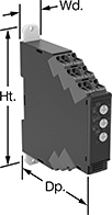
Smart Multifunction Monitoring Relays

Remotely control these relays through an app on your smartphone—they simultaneously monitor phase, voltage, and frequency. The downloadable app lets you change the tripping range, modify settings, and save programs to apply to multiple relays. Tap your smartphone or tablet to the relays to connect to them. They use NFC (near field communication), so you don’t need to manually pair them like Bluetooth devices.
You’ll often see these relays used to protect motors, generators, and other three-phase circuits from burning out or overheating. They'll switch the circuit off if they detect voltage or frequencies outside of the set range or phase loss, imbalance, or reversal. You can see that they're wired correctly and when they're actuated based on the LED indicators. Rated IP20, they have recessed terminals that keep fingers and other objects from touching live circuits. Mount them on a 35 mm DIN rail (also known as DIN 3 rail) for fast installation.
![]() For technical drawings and 3-D models, click on a part number.
For technical drawings and 3-D models, click on a part number.
Trip Voltage | Trip Frequency | |||||||||||||||
|---|---|---|---|---|---|---|---|---|---|---|---|---|---|---|---|---|
| Number of Terminals | Input Voltage | Min. | Max. | Input Frequency, Hz | Min., Hz | Max., Hz | Trip Time, sec. | Reset Type | Switching Current @ Voltage | Max. Switching Voltage | Ht. | Wd. | Dp. | Operating System Compatibility | Each | |
2 Circuits Controlled with 2 Off (Normally Open) or 2 On (Normally Closed)—DPDT | ||||||||||||||||
With Screw Terminals | ||||||||||||||||
| 12 | 208V AC, 240V AC, 300V AC, 480V AC | 208V AC | 480V AC | 50, 60 | 45 | 66 | 0.1-60 | Automatic | 8 A @ 240 V AC | 250V AC | 3.5" | 0.9" | 3.9" | Android 7.0 or Later, iOS 14.5 or Later | 0000000 | 0000000 |
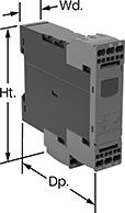
Voltage-Monitoring Relays
Safeguard your equipment against overheating, wear, and malfunction from a spike or dip in voltage. These relays continuously monitor your AC or DC power supply and trip when the voltage is outside a set range. Rated IP20, these relays have recessed terminals that keep fingers and other objects from touching live circuits. Mount them on a 35 mm DIN rail (also known as DIN 3 rail) for fast installation.
Relays have knobs right on the front where you can set your trip voltage. You can see that they're wired correctly and when they're actuated based on the LED indicators. If you want to mount these relays to a surface instead of DIN rail, they have mounting holes.
Relays with IO link can be programmed, monitored and reset remotely by connecting them to a programmable logic controller (PLC), human-machine interface (HMI), or computer. If you want to program them locally, they have a keypad.
Relays with spring-clamp terminals connect and disconnect to wire without screws. Because there’s no screw, these connections are less likely to loosen over time, even in high-vibration environments.
![]() For technical drawings and 3-D models, click on a part number.
For technical drawings and 3-D models, click on a part number.
| Number of Terminals | Input Voltage | Trip Voltage Setting | Trip Time, sec. | Reset Type | Switching Current @ Voltage | Max. Switching Voltage | Adjustment Style | Ht. | Wd. | Dp. | Features | Each | |
1 Circuit Controlled with 1 Off (Normally Open) or 1 On (Normally Closed)—SPDT | |||||||||||||
|---|---|---|---|---|---|---|---|---|---|---|---|---|---|
With Spring-Clamp Terminals | |||||||||||||
| 9 | 24V AC, 24V DC | 1-10V AC/DC 3-30V AC/DC 15-150V AC/DC | 0.1-30 | Automatic, Manual | 5 A @ 240 V AC 5 A @ 30 V DC | 250V AC 48V DC | Knob | 3.5" | 0.7" | 3.5" | LED Indicator | 00000000 | 0000000 |
| 9 | 24V AC, 24V DC | 20-200V AC/DC 30-300V AC/DC 60-600V AC/DC | 0.1-30 | Automatic, Manual | 5 A @ 240 V AC 5 A @ 30 V DC | 250V AC 48V DC | Knob | 3.5" | 0.7" | 3.5" | LED Indicator | 00000000 | 000000 |
| 9 | 120V AC, 240V AC | 1-10V AC/DC 3-30V AC/DC 15-150V AC/DC | 0.1-30 | Automatic, Manual | 5 A @ 240 V AC 5 A @ 30 V DC | 250V AC 48V DC | Knob | 3.5" | 0.7" | 3.5" | LED Indicator | 00000000 | 000000 |
| 9 | 120V AC, 240V AC | 20-200V AC/DC 30-300V AC/DC 60-600V AC/DC | 0.1-30 | Automatic, Manual | 5 A @ 240 V AC 5 A @ 30 V DC | 250V AC 48V DC | Knob | 3.5" | 0.7" | 3.5" | LED Indicator | 00000000 | 000000 |
Trip Voltage | |||||||||||||||
|---|---|---|---|---|---|---|---|---|---|---|---|---|---|---|---|
| Number of Terminals | Input Voltage | Min. | Max. | Trip Time, sec. | Reset Type | Switching Current @ Voltage | Max. Switching Voltage | Adjustment Style | Ht. | Wd. | Dp. | Display Type | Features | Each | |
1 Circuit Controlled with 1 Off (Normally Open) or 1 On (Normally Closed)—SPDT | |||||||||||||||
With Screw Terminals | |||||||||||||||
| 9 | 24V DC | 10V AC/DC | 600V AC/DC | 0-999 | Automatic | 3 A @ 240 V AC 1 A @ 24 V DC | 400V AC 250V DC | Keypad, External Controller | 3.6" | 0.9" | 3.6" | LCD | Remote Reset | 00000000 | 0000000 |
With Spring-Clamp Terminals | |||||||||||||||
| 9 | 24V DC | 10V AC/DC | 600V AC/DC | 0-999 | Automatic | 3 A @ 240 V AC 1 A @ 24 V DC | 400V AC 250V DC | Keypad, External Controller | 3.8" | 0.9" | 3.6" | LCD | Remote Reset | 00000000 | 000000 |
Multifunction Monitoring Relays
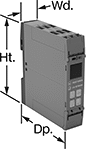
Monitor phase, voltage, and frequency at the same time to protect motors, generators, and other three-phase circuits from burning out or overheating. They'll switch the circuit off if they detect voltage or frequencies outside of the set range or phase loss, imbalance, or reversal. Rated IP20, they have recessed terminals that keep fingers and other objects from touching live circuits. Mount them on a 35 mm DIN (also known as DIN 3 rail) for fast installation.
These relays use IO Link, so they can be programmed, monitored, and reset remotely by connecting them to a programmable logic controller (PLC), human-machine interface (HMI), or computer. If you want to program them locally, they have a keypad.
Relays with spring-clamp terminals connect and disconnect to wire without screws. Because there’s no screw, these connections are less likely to loosen over time, even in high-vibration environments.
![]() For technical drawings and 3-D models, click on a part number.
For technical drawings and 3-D models, click on a part number.
Trip Voltage | Trip Frequency | |||||||||||||||
|---|---|---|---|---|---|---|---|---|---|---|---|---|---|---|---|---|
| Number of Terminals | Input Voltage | Min. | Max. | Input Frequency, Hz | Min., Hz | Max., Hz | Trip Time, sec. | Reset Type | Switching Current @ Voltage | Max. Switching Voltage | Adjustment Style | Ht. | Wd. | Dp. | Each | |
1 Circuit Controlled with 1 Off (Normally Open) or 1 On (Normally Closed)—SPDT | ||||||||||||||||
With Screw Terminals and IO Link | ||||||||||||||||
| 12 | 24V DC | 90V AC | 760V AC | 50, 60 | 15 | 70 | 0.1-30 | Automatic | 3 A @ 240 V AC 1 A @ 24 V DC | 400V AC 250V DC | Keypad, External Controller | 3.9" | 0.9" | 3.6" | 0000000 | 0000000 |
With Spring-Clamp Terminals and IO Link | ||||||||||||||||
| 12 | 24V DC | 90V AC | 760V AC | 50, 60 | 15 | 70 | 0.1-30 | Automatic | 3 A @ 240 V AC 1 A @ 24 V DC | 400V AC 250V DC | Keypad, External Controller | 3.9" | 0.9" | 3.6" | 0000000 | 000000 |
Surface-Mount Motor Voltage Monitors
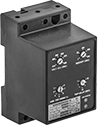
Protect electric motors from phase loss, phase reversal, overvoltage, undervoltage, and voltage imbalance. Also known as voltage-monitoring relays, these monitors cut power to a motor when a fault occurs.
![]() For technical drawings and 3-D models, click on a part number.
For technical drawings and 3-D models, click on a part number.
Trip Time, sec. | Switching | |||||||||||
|---|---|---|---|---|---|---|---|---|---|---|---|---|
| Input Voltage Range | No. of Terminals | Control Power, W | Voltage Imbalance Adjustment | Automatic Reset | Delayed Automatic Reset | Current, A | Voltage | Ht. | Wd. | Specifications Met | Each | |
1 Circuit Controlled with 1 Off (Normally Open) or 1 On (Normally Closed)—SPDT | ||||||||||||
Three Phase | ||||||||||||
| 190-480V AC | 7 | 6 | 2%-8% | 1-30 | 1-500 | 10 | 240V AC | 3.5" | 2.08" | UL Listed | 0000000 | 0000000 |
| 475-600V AC | 7 | 6 | 2%-8% | 1-30 | 1-500 | 10 | 240V AC | 3.5" | 2.08" | UL Listed | 0000000 | 000000 |
DIN-Rail Mount Motor Voltage Monitors
Mount these monitors to 35 mm DIN rail. They protect electric motors from phase loss, phase reversal, overvoltage, undervoltage, and voltage imbalance. Also known as voltage-monitoring relays, they cut power to a motor when a fault occurs.
![]() For technical drawings and 3-D models, click on a part number.
For technical drawings and 3-D models, click on a part number.
Switching | |||||||||||||
|---|---|---|---|---|---|---|---|---|---|---|---|---|---|
| Input Voltage Range | No. of Terminals | Control Power, W | Voltage Imbalance Adjustment | Trip Time, sec. | Reset Type | Current, A | Voltage | Horsepower @ Voltage | Ht. | Wd. | Specifications Met | Each | |
1 Circuit Controlled with 1 Off (Normally Open) or 1 On (Normally Closed)—SPDT | |||||||||||||
Three Phase | |||||||||||||
| 200-480V AC | 9 | 5 | 2%-10% | 1-30 | Automatic | 10 | 240V AC | 1/3 hp @ 240 V AC | 3" | 2" | UL Listed, C-UL Listed | 0000000 | 0000000 |
Socket-Mount Motor Voltage Monitors

Plug these monitors into relay sockets for fast installation and replacement. They protect electric motors from phase loss, phase reversal, overvoltage, undervoltage, and voltage imbalance. Also known as voltage-monitoring relays, they cut power to a motor when a fault occurs.
Relay sockets (sold separately) mount to 35 mm DIN rail or flat surfaces.
Voltage Monitors | ||||||||||||||
|---|---|---|---|---|---|---|---|---|---|---|---|---|---|---|
Switching | Relay Sockets | |||||||||||||
| Input Voltage Range | No. of Terminals | Control Power, W | Voltage Imbalance Adjustment | Trip Time, sec. | Reset Type | Current, A | Voltage | Ht. | Wd. | Specifications Met | Each | Each | ||
1 Circuit Controlled with 1 Off (Normally Open) or 1 On (Normally Closed)—SPDT | ||||||||||||||
Three Phase | ||||||||||||||
| 200-480V AC | 8 | 5 | 2%-10% | 0.25-30 | Automatic | 10 | 240V AC | 2.4" | 1.8" | UL Recognized Component, CSA Certified | 0000000 | 0000000 | 0000000 | 00000 |
Overload Protectors for Motor Starters

Upgrade motor starters that use thermal overload protection with these solid-state overloads—they don't use heating elements, so enclosure ventilation and cooling is not required. All have a full-load amp adjustment dial to accommodate circuits with different full-load amp ratings.
If the full-load amp rating is not shown on your motor’s faceplate, estimate the current rating (given the motor’s horsepower and voltage).
![]() For technical drawings and 3-D models, click on a part number.
For technical drawings and 3-D models, click on a part number.
| Overload Current, A | Trip Time, sec. | Overload Protection Class | Motor Protection | Ht. | Wd. | Dp. | Wire Connection Type | Specifications Met | Each | |
2 Auxilliary Contacts with 1 Off (Normally Open), 1 On (Normally Closed) | ||||||||||
|---|---|---|---|---|---|---|---|---|---|---|
Single Phase | ||||||||||
| 3-12 | 5, 10, 20, 30 | 5, 10, 20, 30 | Overvoltage, Phase Loss | 2.2" | 3.5" | 3.2" | Screw Terminals | UL Listed, CSA Certified | 0000000 | 0000000 |
| 5.5-22 | 5, 10, 20, 30 | 5, 10, 20, 30 | Overvoltage, Phase Loss | 2.2" | 3.5" | 3.2" | Screw Terminals | UL Listed, CSA Certified | 0000000 | 000000 |
Three Phase | ||||||||||
| 0.75-3.4 | 5, 10, 20, 30 | 5, 10, 20, 30 | Overvoltage, Phase Loss | 3.2" | 3.5" | 3.2" | Screw Terminals | UL Listed, CSA Certified | 0000000 | 000000 |
| 3-12 | 5, 10, 20, 30 | 5, 10, 20, 30 | Overvoltage, Phase Loss | 2.2" | 3.5" | 3.2" | Screw Terminals | UL Listed, CSA Certified | 0000000 | 000000 |
| 5.5-22 | 5, 10, 20, 30 | 5, 10, 20, 30 | Overvoltage, Phase Loss | 2.2" | 3.5" | 3.2" | Screw Terminals | UL Listed, CSA Certified | 0000000 | 000000 |
| 10-40 | 5, 10, 20, 30 | 5, 10, 20, 30 | Overvoltage, Phase Loss | 2.2" | 3.5" | 3.2" | Screw Terminals | UL Listed, CSA Certified | 0000000 | 000000 |
| 13-52 | 5, 10, 20, 30 | 5, 10, 20, 30 | Overvoltage, Phase Loss | 2.3" | 4.5" | 4" | Screw Terminals | UL Listed, CSA Certified | 0000000 | 000000 |
| 25-100 | 5, 10, 20, 30 | 5, 10, 20, 30 | Overvoltage, Phase Loss | 2.3" | 4.5" | 4" | Screw Terminals | UL Listed, CSA Certified | 0000000 | 000000 |