


Matching Flow Diagrams to Replace an Air Directional Control Valve
More
Choosing an Air Directional Control Valve
More
About Flow Control Valves
Also known as cylinder speed controls, flow control valves let you control the extension or retraction speed of your air cylinder. They regulate airflow as it passes from the valve's inlet to its outlet. Air flows freely in the opposite direction.
More
Tamper-Resistant Air Flow Control Valves
Prevent accidental airflow changes with these valves, which require an adjustment tool (sold separately) to alter their flow rate. Use them to control the speed of air-powered equipment by adjusting the volume of airflow. They control flow in one direction as air moves from the inlet to the outlet. Air flows freely in the opposite direction. The elbow shape allows you to mount them directly to cylinder ports, eliminating additional tubing or piping between the cylinder and valve for better control and consistency than inline valves.
Meter out valves control flow as it exits the cylinder. Meter in valves control flow as it enters the cylinder.
Valves with push-to-connect ports are for use with plastic or soft metal tubing. Insert tubing into the port.
Flow coefficient (Cv) is a measurement that indicates how much airflow can pass through a valve. When selecting between valves with the same port size, choose the valve with the higher flow coefficient to ensure it provides enough airflow to operate your system.
![]() For technical drawings and 3-D models, click on a part number.
For technical drawings and 3-D models, click on a part number.


Flow Rate @ 73 psi | |||||||||||
|---|---|---|---|---|---|---|---|---|---|---|---|
| Inlet Pipe Size | For Outlet Tube OD | Flow Coefficient (Cv) | Min. | Max. | Max. Pressure, psi | Temp. Range, °F | Flow Adjustment Mechanism | Flow Control Type | ISO Designation | Each | |
PBT Plastic Body | |||||||||||
| 1/8 | 1/8" | 0.15 | 0scfm | 7.2scfm | 145 | 32° to 140° | Tamper-Resistant Screw | Exiting Cylinder | Meter Out | 0000000 | 000000 |
| 1/8 | 1/4" | 0.19 | 0scfm | 9.2scfm | 145 | 32° to 140° | Tamper-Resistant Screw | Exiting Cylinder | Meter Out | 0000000 | 00000 |
| 1/4 | 1/4" | 0.39 | 0scfm | 18.4scfm | 145 | 32° to 140° | Tamper-Resistant Screw | Exiting Cylinder | Meter Out | 0000000 | 00000 |
| 1/4 | 3/8" | 0.39 | 0scfm | 18.4scfm | 145 | 32° to 140° | Tamper-Resistant Screw | Exiting Cylinder | Meter Out | 0000000 | 00000 |
| 3/8 | 1/4" | 0.56 | 0scfm | 27.2scfm | 145 | 32° to 140° | Tamper-Resistant Screw | Exiting Cylinder | Meter Out | 0000000 | 00000 |
| 3/8 | 3/8" | 0.78 | 0scfm | 36.8scfm | 145 | 32° to 140° | Tamper-Resistant Screw | Exiting Cylinder | Meter Out | 0000000 | 00000 |
| 1/2 | 3/8" | 1.33 | 0scfm | 63.2scfm | 145 | 32° to 140° | Tamper-Resistant Screw | Exiting Cylinder | Meter Out | 0000000 | 00000 |
| 1/2 | 1/2" | 1.44 | 0scfm | 68.4scfm | 145 | 32° to 140° | Tamper-Resistant Screw | Exiting Cylinder | Meter Out | 0000000 | 00000 |
| Adjustment Tools | 0000000 | Each | 00000 |


Flow Rate @ 73 psi | |||||||||||
|---|---|---|---|---|---|---|---|---|---|---|---|
| For Inlet Tube OD | Outlet Pipe Size | Flow Coefficient (Cv) | Min. | Max. | Max. Pressure, psi | Temp. Range, °F | Flow Adjustment Mechanism | Flow Control Type | ISO Designation | Each | |
PBT Plastic Body | |||||||||||
| 1/8" | 1/8 | 0.15 | 0scfm | 7.2scfm | 145 | 32° to 140° | Tamper-Resistant Screw | Entering Cylinder | Meter In | 0000000 | 000000 |
| 1/4" | 1/4 | 0.39 | 0scfm | 18.4scfm | 145 | 32° to 140° | Tamper-Resistant Screw | Entering Cylinder | Meter In | 0000000 | 00000 |
| 1/4" | 1/8 | 0.19 | 0scfm | 9.2scfm | 145 | 32° to 140° | Tamper-Resistant Screw | Entering Cylinder | Meter In | 0000000 | 00000 |
| 1/4" | 3/8 | 0.56 | 0scfm | 27.2scfm | 145 | 32° to 140° | Tamper-Resistant Screw | Entering Cylinder | Meter In | 0000000 | 00000 |
| 3/8" | 1/2 | 1.33 | 0scfm | 63.2scfm | 145 | 32° to 140° | Tamper-Resistant Screw | Entering Cylinder | Meter In | 0000000 | 00000 |
| 3/8" | 1/4 | 0.39 | 0scfm | 18.4scfm | 145 | 32° to 140° | Tamper-Resistant Screw | Entering Cylinder | Meter In | 0000000 | 00000 |
| 3/8" | 3/8 | 0.78 | 0scfm | 36.8scfm | 145 | 32° to 140° | Tamper-Resistant Screw | Entering Cylinder | Meter In | 0000000 | 00000 |
| 1/2" | 1/2 | 1.44 | 0scfm | 68.4scfm | 145 | 32° to 140° | Tamper-Resistant Screw | Entering Cylinder | Meter In | 0000000 | 00000 |
| Adjustment Tools | 0000000 | Each | 00000 |
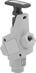
Key-Operated Single-Action Air Directional Control Valves
Because they require a key to operate, you can limit who is able to adjust these valves. Also known as 3-way and 3/2 valves, they create one action, such as extending a cylinder. Valves direct airflow from the inlet to your equipment and exhaust return airflow to create motion. They're normally closed to block airflow until actuated. Return actuation is by hand, so they stay actuated and return to their starting position only when you move the actuator again. In the off position, they exhaust air pressure from the system to the atmosphere, allowing equipment to reset so the action can be repeated.
Flow coefficient (Cv) is a measurement that indicates how much airflow can pass through a valve.
![]() For technical drawings and 3-D models, click on a part number.
For technical drawings and 3-D models, click on a part number.
Overall | ||||||||||||||
|---|---|---|---|---|---|---|---|---|---|---|---|---|---|---|
| No. of Flow Ports | Inlet Size | Outlet Size | Max. Flow Rate, scfm @ 100 psi | Flow Coefficient (Cv) | Pressure Range, psi | Vacuum Rating, in. of Hg | Lg. | Wd. | Ht. | For Panel Cutout Dia. | Mounting Fasteners Included | No. of Keys Included | Each | |
Threaded Female Inlet × Threaded Female Outlet | ||||||||||||||
| 3 | 1/4 NPT | 1/4 NPT | 33.53 | 1.05 | 0-145 | 29.5 | 1 5/8" | 1 5/8" | 4 1/8" | 1 1/8" | No | 2 | 000000 | 000000 |
Safety-Lockout Single-Action Air Directional Control Valves
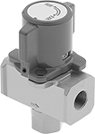
To prevent accidental start-up, these valves can be locked in their off position with a padlock. Also known as 3-way and 3/2 valves, they create one action, such as extending a cylinder. Valves direct airflow from the inlet to your equipment and exhaust return airflow to create motion. They're normally closed to block airflow until actuated. Return actuation is by hand, so they stay actuated and return to their starting position only when you move the actuator again. In the off position, they exhaust air pressure from the system, allowing equipment to reset so the action can be repeated. They help meet OSHA 29 CFR 1910.147 procedures for the control of energy sources that could injure workers.
Flow coefficient (Cv) is a measurement that indicates how much airflow can pass through a valve.
![]() For technical drawings and 3-D models, click on a part number.
For technical drawings and 3-D models, click on a part number.
Overall | ||||||||||||||||
|---|---|---|---|---|---|---|---|---|---|---|---|---|---|---|---|---|
| No. of Flow Ports | Inlet Size | Outlet Size | Exhaust Connection Type | Max. Flow Rate, scfm @ 100 psi | Flow Coefficient (Cv) | Pressure Range, psi | Vacuum Rating | Specifications Met | Lg. | Wd. | Ht. | Mounting Fasteners Included | Padlock Included | For Max. Padlock Shackle Dia. | Each | |
Threaded Female Inlet × Threaded Female Outlet | ||||||||||||||||
| 3 | 1/8 NPT | 1/8 NPT | Threaded | 5 | 0.65 | 15-145 | Not Rated | OSHA Compliant 29 CFR 1910.147 | 1 5/8" | 1 3/4" | 2 5/8" | No | No | 25/64" | 00000000 | 000000 |
| 3 | 1/4 NPT | 1/4 NPT | Threaded | 113 | 2 | 15-145 | Not Rated | OSHA Compliant 29 CFR 1910.147 | 2 3/4" | 2 1/2" | 4 1/4" | No | No | 25/64" | 00000000 | 00000 |
| 3 | 3/8 NPT | 3/8 NPT | Threaded | 116 | 3 | 15-145 | Not Rated | OSHA Compliant 29 CFR 1910.147 | 2 3/4" | 2 1/2" | 4 1/4" | No | No | 25/64" | 00000000 | 00000 |
| 3 | 1/2 NPT | 1/2 NPT | Threaded | 215 | 3.8 | 15-145 | Not Rated | OSHA Compliant 29 CFR 1910.147 | 2 3/4" | 2 1/2" | 4 1/4" | No | No | 25/64" | 00000000 | 00000 |
| 3 | 3/4 NPT | 3/4 NPT | Threaded | 361 | 6.4 | 15-145 | Not Rated | OSHA Compliant 29 CFR 1910.147 | 3 5/8" | 3 1/4" | 5 3/8" | No | No | 25/64" | 00000000 | 00000 |
| 3 | 1 NPT | 1 NPT | Threaded | 481 | 8.6 | 15-145 | Not Rated | OSHA Compliant 29 CFR 1910.147 | 3 5/8" | 3 1/4" | 5 3/8" | No | No | 25/64" | 00000000 | 00000 |
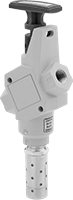
Key-Operated Two-Speed Two-Action Air Directional Control Valves
Because they require a key to operate, you can limit who is able to adjust these valves. Often used to extend and then retract a cylinder at different speeds, they create two actions and have two exhaust ports, which allows you to control the speed of each action by attaching a flow control valve to each exhaust port. They direct airflow from the inlet to your equipment and exhaust return airflow to create motion. Return actuation is by hand, so they stay actuated and return to their original position only when you move the actuator again. Also known as 4-way and 5/2 valves.
Flow coefficient (Cv) is a measurement that indicates how much airflow can pass through a valve.
![]() For technical drawings and 3-D models, click on a part number.
For technical drawings and 3-D models, click on a part number.
Overall | |||||||||||||||
|---|---|---|---|---|---|---|---|---|---|---|---|---|---|---|---|
| No. of Flow Ports | Inlet Size | Outlet Size | Exhaust Connection Type | Max. Flow Rate, scfm @ 100 psi | Flow Coefficient (Cv) | Pressure Range, psi | Vacuum Rating, in. of Hg | Lg. | Wd. | Ht. | For Panel Cutout Dia. | Mounting Fasteners Included | No. of Keys Included | Each | |
Threaded Female Inlet × Threaded Female Outlet | |||||||||||||||
| 5 | 1/8 NPT | 1/8 NPT | Threaded | 11.3 | 0.34 | 14-145 | 26.5 | 7/8" | 1 5/8" | 5 5/8" | 1 1/4" | No | 2 | 0000000 | 0000000 |
Quiet Safety-Lockout Air On/Off Valves
The muffler on these valves reduces exhaust noise. A padlock (not included) locks the handle in the shut-off position to disconnect air tools safely. They comply with OSHA 29 CFR 1910.147 to maintain safety and control in a compressed air system.
Flow coefficient (Cv) is a measurement that indicates how much airflow can pass through a valve.
![]() For technical drawings and 3-D models, click on a part number.
For technical drawings and 3-D models, click on a part number.
Overall | ||||||||||||
|---|---|---|---|---|---|---|---|---|---|---|---|---|
| Inlet Pipe Size | Outlet Pipe Size | Exhaust Pipe Size | Flow Coefficient (Cv) | Max. Pressure, psi | Temp. Range, °F | Lg. | Wd. | Ht. | For Max. Padlock Shackle Dia. | Specifications Met | Each | |
NPT Female Inlet, Outlet, and Exhaust | ||||||||||||
Aluminum Body | ||||||||||||
| 1/4 | 1/4 | 3/8 | 3.2 | 150 | 40° to 175° | 3 5/8" | 1 3/16" | 8" | 9/32" | OSHA Compliant 29 CFR 1910.147 | 00000000 | 0000000 |
| 3/8 | 3/8 | 3/8 | 3.2 | 150 | 40° to 175° | 3 5/8" | 1 3/16" | 8" | 9/32" | OSHA Compliant 29 CFR 1910.147 | 00000000 | 000000 |
| 1/2 | 1/2 | 3/4 | 5.9 | 150 | 40° to 175° | 4 7/16" | 2" | 11 1/2" | 9/32" | OSHA Compliant 29 CFR 1910.147 | 00000000 | 000000 |
| 3/4 | 3/4 | 3/4 | 5.9 | 150 | 40° to 175° | 4 7/16" | 2" | 11 1/2" | 9/32" | OSHA Compliant 29 CFR 1910.147 | 00000000 | 000000 |
| 1 | 1 | 1 1/4 | 17.4 | 150 | 40° to 175° | 5 1/2" | 2.3" | 14 3/4" | 9/32" | OSHA Compliant 29 CFR 1910.147 | 00000000 | 000000 |
| 1 1/4 | 1 1/4 | 1 1/4 | 17.4 | 150 | 40° to 175° | 5 1/2" | 2.3" | 14 3/4" | 9/32" | OSHA Compliant 29 CFR 1910.147 | 00000000 | 000000 |
Safety-Lockout Air On/Off Valves
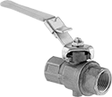

A padlock (not included) locks the handle of these valves in the shut-off position. When valves are closed, the exhaust port vents air pressure so you can disconnect air tools safely. They meet OSHA lockout requirements to maintain safety and control in a compressed air system.
Flow coefficient (Cv) is a measurement that indicates how much airflow can pass through a valve. When selecting between valves with the same port size, choose the valve with the higher flow coefficient to ensure it provides enough airflow to operate your system.
Valves that comply with OSHA 29 CFR 1910.147 meet standards for the control of energy sources that could injure workers.
![]() For technical drawings and 3-D models, click on a part number.
For technical drawings and 3-D models, click on a part number.
Flow Rate @ 100 psi | Overall | |||||||||||||
|---|---|---|---|---|---|---|---|---|---|---|---|---|---|---|
| Inlet Pipe Size | Outlet Pipe Size | Exhaust Pipe Size | Flow Coefficient (Cv) | Min. | Max. | Max. Pressure, psi | Temp. Range, °F | Lg. | Wd. | Ht. | For Max. Padlock Shackle Dia. | Specifications Met | Each | |
Brass Body | ||||||||||||||
| 1 1/4 | 1 1/4 | 1/4 | 86 | Not Rated | Not Rated | 200 | 32° to 210° | 8" | 2 5/16" | 4 3/4" | 9/32" | OSHA Compliant 29 CFR 1910.147 | 0000000 | 000000 |
| 1 1/2 | 1 1/2 | 1/4 | 140 | Not Rated | Not Rated | 200 | 32° to 210° | 8 3/16" | 2 13/16" | 5 1/4" | 9/32" | OSHA Compliant 29 CFR 1910.147 | 0000000 | 000000 |
| 2 | 2 | 1/4 | 190 | Not Rated | Not Rated | 200 | 32° to 210° | 8 9/16" | 3 3/8" | 5 3/4" | 9/32" | OSHA Compliant 29 CFR 1910.147 | 0000000 | 000000 |
Bronze Body | ||||||||||||||
| 1/4 | 1/4 | 1/4 | Not Rated | Not Rated | Not Rated | 200 | 50° to 200° | 4 7/8" | 1 1/16" | 3" | 1/4" | __ | 0000000 | 00000 |
| 3/8 | 3/8 | 1/4 | Not Rated | Not Rated | Not Rated | 200 | 50° to 200° | 4 7/8" | 1 1/16" | 3" | 1/4" | __ | 0000000 | 00000 |
| 1/2 | 1/2 | 1/4 | 15 | Not Rated | Not Rated | 200 | 50° to 200° | 4 15/16" | 1 3/16" | 3 1/16" | 1/4" | __ | 0000000 | 00000 |
| 3/4 | 3/4 | 1/4 | 51 | Not Rated | Not Rated | 200 | 50° to 200° | 6 7/16" | 1 13/16" | 3 11/16" | 1/4" | __ | 0000000 | 000000 |
| 1 | 1 | 1/4 | 68 | Not Rated | Not Rated | 200 | 50° to 200° | 7 5/16" | 2 1/4" | 4 3/8" | 1/4" | __ | 0000000 | 000000 |
Aluminum Body | ||||||||||||||
| 1/4 | 1/4 | 3/8 | 1.8 | Not Rated | Not Rated | 145 | 40° to 175° | 1" | 1" | 6 1/2" | 9/32" | OSHA Compliant 29 CFR 1910.147 | 00000000 | 000000 |
| 3/8 | 3/8 | 3/8 | 2.6 | Not Rated | Not Rated | 145 | 40° to 175° | 1" | 1" | 6 1/2" | 9/32" | OSHA Compliant 29 CFR 1910.147 | 00000000 | 000000 |
| 1/2 | 1/2 | 3/4 | 4 | 0 scfm | 91 scfm | 300 | 40° to 175° | 4 1/4" | 2" | 9" | 1/4" | OSHA Compliant 29 CFR 1910.147 | 0000000 | 000000 |
| 1/2 | 1/2 | 3/4 | 7.1 | Not Rated | Not Rated | 300 | 40° to 175° | 4 7/16" | 2" | 8 7/8" | 9/32" | OSHA Compliant 29 CFR 1910.147 | 00000000 | 000000 |
| 3/4 | 3/4 | 3/4 | 4 | 0 scfm | 93 scfm | 300 | 40° to 175° | 4 1/4" | 2" | 9" | 1/4" | OSHA Compliant 29 CFR 1910.147 | 0000000 | 000000 |
| 3/4 | 3/4 | 3/4 | 8.2 | Not Rated | Not Rated | 300 | 40° to 175° | 4 7/16" | 2" | 8 7/8" | 9/32" | OSHA Compliant 29 CFR 1910.147 | 00000000 | 000000 |
| 1 | 1 | 1 1/4 | 9.4 | 0 scfm | 216 scfm | 300 | 40° to 175° | 4 1/4" | 2 1/4" | 9" | 1/4" | OSHA Compliant 29 CFR 1910.147 | 0000000 | 000000 |
| 1 | 1 | 1 1/4 | 16.5 | Not Rated | Not Rated | 300 | 40° to 175° | 5 1/2" | 2.3" | 10 13/16" | 9/32" | OSHA Compliant 29 CFR 1910.147 | 00000000 | 000000 |
| 1 1/4 | 1 1/4 | 1 1/4 | 19.2 | Not Rated | Not Rated | 300 | 40° to 175° | 5 1/2" | 2.3" | 10 13/16" | 9/32" | OSHA Compliant 29 CFR 1910.147 | 00000000 | 000000 |
Overall | ||||||||||||
|---|---|---|---|---|---|---|---|---|---|---|---|---|
| Inlet Pipe Size | Outlet Pipe Size | Exhaust Thread Size | Flow Coefficient (Cv) | Max. Pressure, psi | Temp. Range, °F | Lg. | Wd. | Ht. | For Max. Padlock Shackle Dia. | Specifications Met | Each | |
Brass Body | ||||||||||||
| 1/4 | 1/4 | 10-32 | 6.29 | 200 | -40° to 350° | 4 5/8" | 1 1/8" | 2 5/8" | 9/32" | OSHA Compliant 29 CFR 1910.147 | 0000000 | 000000 |
| 3/8 | 3/8 | 10-32 | 6.99 | 200 | -40° to 350° | 4 5/8" | 1 1/8" | 2 5/8" | 9/32" | OSHA Compliant 29 CFR 1910.147 | 0000000 | 00000 |
| 1/2 | 1/2 | 10-32 | 19 | 200 | -40° to 350° | 4 15/16" | 1 5/16" | 2 13/16" | 9/32" | OSHA Compliant 29 CFR 1910.147 | 0000000 | 00000 |
| 3/4 | 3/4 | 10-32 | 34.4 | 200 | -40° to 350° | 5 13/16" | 1 9/16" | 3 5/16" | 9/32" | OSHA Compliant 29 CFR 1910.147 | 0000000 | 00000 |
| 1 | 1 | 10-32 | 50.1 | 200 | -40° to 350° | 6 3/16" | 1 15/16" | 3 11/16" | 9/32" | OSHA Compliant 29 CFR 1910.147 | 0000000 | 00000 |