Choosing a Proximity Switch
More
Choosing an Electrical Switch
More
Foot Switches

Keep your hands free for other tasks by triggering switches with your foot.
Back-pivot switches actuate with a tap of the toe. Optional guards prevent accidental switch actuation.
Switches | ||||||||||||||
|---|---|---|---|---|---|---|---|---|---|---|---|---|---|---|
Mounting | Optional Guards | |||||||||||||
| No. of Circuits Controlled | Switch Starting Position | Switch Action | Industry Designation | Switching Current @ Voltage | Housing Material | Wire Connection Type | No. of Terminals | Fasteners Included | No. of Holes | Hole Dia. | Each | Each | ||
1 Speed | ||||||||||||||
Back Pivot with 1 Pedal | ||||||||||||||
| 2 | 2 Off (Normally Open) or 2 On (Normally Closed) | Springs Back (Momentary) | DPDT | 15 A @ 125 V AC, 10 A @ 250 V AC, 3 A @ 3 V DC | Iron | Quick-Disconnect Terminals | 6 | No | 2 | 0.22" | 000000 | 000000 | 000000 | 000000 |
Circuit Board DC Magnetic-Object Proximity Switches
Send signals in response to changing magnetic fields to trigger processes or monitor position, speed, and current. These switches communicate with devices such as programmable logic controllers (PLCs) and microcontrollers. They’re also known as hall effect sensors. To install, push their contacts through holes in a circuit board, then solder them in place.
Momentary switches change their output signal based on whether a magnetic field is present. They’re often used to trigger a process in response to changing magnetic fields, such as turning on a light when a door opens. When they detect a north or south pole, they output a low-voltage signal. When they don’t detect a magnetic field at all, they output a high-voltage signal.
For technical drawings and 3-D models, click on a part number.
| Switch Action | Switch Starting Position | Setpoint, G | Approximate Difference Between Setpoint and Reset Point, G | Switching Frequency, kHz | Switching Current @ Voltage | Max. Voltage | Wire Dia. | Lg., mm | Wd., mm | Ht., mm | Temp. Range, °F | Pkg. Qty. | Pkg. | |
Plastic Housing | ||||||||||||||
|---|---|---|---|---|---|---|---|---|---|---|---|---|---|---|
| Momentary | 1 On (Normally Closed) | 395 | 40 | Not Rated | 0.008 mA @ 3 V DC | 5.5V DC | 0.015" | 3 | 4 | 2 | -40° to 255° | 10 | 0000000 | 000000 |
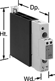
DIN-Rail Mount Solid State Relays

Unlike mechanical relays, these solid state relays have no moving parts, so they require less maintenance and last longer, switch faster, and are quieter. They mount on 35 mm DIN rail (also known as DIN 3) for fast installation. An LED indicator lights up when these relays are connected, so you can quickly confirm that they’re wired correctly. IP20 rated, their terminals are recessed, so they prevent fingers and other objects from touching live circuits.
Relays with an integrated heat sink disperse heat to increase the relay’s current rating.
For technical drawings and 3-D models, click on a part number.
| Number of Terminals | Input Voltage | Control Current, mA | Switching Current @ Voltage (Load Type) | Max. Switching Voltage | Ht. | Wd. | Dp. | Features | Each | |
1 Circuit Controlled with 1 Off (Normally Open)—SPST-NO | ||||||||||
|---|---|---|---|---|---|---|---|---|---|---|
Single Phase | ||||||||||
| 4 | 4V DC, 6V DC, 12V DC, 24V DC, 30V DC | 12 | 4.5 A @ 24 V AC (Full Load) 8 A @ 24 V AC (Resistive Load) 15 A @ 3 V DC | 50V DC | 3.54" | 0.69" | 2.56" | Integrated Heat Sink, LED Indicator | 0000000 | 0000000 |
| 4 | 4V DC, 6V DC, 12V DC, 24V DC, 30V DC | 12 | 4.5 A @ 24 V AC (Full Load) 8 A @ 24 V AC (Resistive Load) 8 A @ 3 V DC | 150V DC | 3.54" | 0.69" | 2.56" | Integrated Heat Sink, LED Indicator | 0000000 | 00000 |


