


Choosing an Electrical Switch
More
12 mm Panel-Mount Push-Button Switches

Switches meet IP ratings for protection from temporary submersion. Install them in a standard panel cutout diameter. They actuate with a quick push.
![]() For technical drawings and 3-D models, click on a part number.
For technical drawings and 3-D models, click on a part number.
| No. of Circuits Controlled | Switch Starting Position | Switch Action | No. of Terminals | Industry Designation | Actuator Color | Switching Current @ Voltage | Max. Voltage | Dia. | Dp. Behind Panel | Environmental Rating | Specifications Met | Each | |
Metal Base | |||||||||||||
|---|---|---|---|---|---|---|---|---|---|---|---|---|---|
With Tab Terminals | |||||||||||||
| 1 | 1 Off (Normally Open) | Springs Back (Momentary) | 2 | SPST-NO | Black | 6 A @ 120 V AC, 5 A @ 12 V DC | 12V DC 240V AC | 7/16" | 13/16" | IP67 | UL Recognized Component | 0000000 | 000000 |
Handle Push-Button Switches
Save space in your setup—these switches double as handles on machines and equipment. Grab the handle and trigger the push-button to open the door and activate the switch in one motion. They’re often used on cages surrounding robotics.
Switches with status indicators alert you when a switch has been actuated.
Add a matching handle without a switch to keep door pulls uniform.
![]() For technical drawings and 3-D models, click on a part number.
For technical drawings and 3-D models, click on a part number.
Switches | Handles without Switch | |||||||||||
|---|---|---|---|---|---|---|---|---|---|---|---|---|
| No. of Circuits Controlled | Switch Starting Position | Switch Action | Actuator Color (Industry Designation) | No. of Terminals | Switching Current @ Voltage | Max. Voltage | Handle Lg. | Plug Type | Each | Each | ||
Glass-Filled Nylon Plastic Handle—Status Indicators | ||||||||||||
| 1 | 1 Off (Normally Open) | Stays Switched (Maintained) | 1 Purple Button (SPST-NO) | 2 | 4 A @ 12 V DC | 48V DC | 6 5/16" | 8-Pole M12 | 0000000 | 0000000 | 0000000 | 000000 |
Push-Pull Switches


The lever sticks out further than a push button, making it easy to identify the position of these switches. They're often used in marine environments.
Switches with a sealed body provide extra protection from moisture and dirt.
Three-position switches close one contact when pulled to the middle position, and close two contacts when pulled all the way.
![]() For technical drawings and 3-D models, click on a part number.
For technical drawings and 3-D models, click on a part number.
Wire Leads | |||||||||||||
|---|---|---|---|---|---|---|---|---|---|---|---|---|---|
| No. of Circuits Controlled | Switch Starting Position | Switch Action | No. of Terminals | Industry Designation | Switch Position (Function) | Switching Current @ Voltage | Max. Voltage | Dia. | Dp. Behind Panel | No. of | Lg. | Each | |
Brass Actuator with Screw Terminals | |||||||||||||
2 Positions | |||||||||||||
| 1 | 1 Off (Normally Open) | Stays Switched (Maintained) | 3 | SPST-NO | In (Off), Out (On) | 10 A @ 12 V DC | 24V DC | 3/4" | 2 1/8" | __ | __ | 0000000 | 000000 |
| 1 | 1 Off (Normally Open) or 1 On (Normally Closed) | Stays Switched (Maintained) | 3 | SPDT | In (Off or On), Out (On or Off) | 10 A @ 12 V DC | 24V DC | 7/8" | 2 1/8" | __ | __ | 0000000 | 00000 |
3 Positions | |||||||||||||
| 1 | 1 Off (Normally Open) or 1 On (Normally Closed) | Stays Switched (Maintained) | 3 | SPDT | In (Off), Center (On), Out (On) | 10 A @ 12 V DC | 24V DC | 3/4" | 2 7/8" | __ | __ | 0000000 | 00000 |
Brass Actuator with Wire Leads and Sealed Body | |||||||||||||
2 Positions | |||||||||||||
| 1 | 1 Off (Normally Open) | Stays Switched (Maintained) | 2 | SPST-NO | In (Off), Out (On) | 10 A @ 12 V DC | 24V DC | 7/8" | 2" | 2 | 8" | 0000000 | 00000 |
Tilt Switches

Often used as position indicators, pump level controls, and machine limit switches, these switches actuate when tilted to a certain angle. They mount horizontally and activate when tilted downward, and deactivate when tilted up. Differential angle is the total angle from the point of activation to the point of deactivation. All combine electromechanical and solid state technologies for reliability and long life.
![]() For technical drawings and 3-D models, click on a part number.
For technical drawings and 3-D models, click on a part number.
| No. of Circuits Controlled | Switch Starting Position | Industry Designation | Switching Current @ Voltage | Max. Voltage | Differential Angle | No. of Wire Leads | Lg. | Ht. | Dp. | Housing Material | Environmental Rating | Each | ||
With Wire Leads | ||||||||||||||
|---|---|---|---|---|---|---|---|---|---|---|---|---|---|---|
| C | 1 | 1 Off (Normally Open) | SPST-NO | 10 A @ 12 V DC | 18V DC | 30° | 2 | 1.22" | 1.07" | 0.8" | Plastic | NEMA 4, IP67 | 000000 | 000000 |
Potentiometers

Vary electrical flow to control speed, volume, and light intensity. The number of turns affects the resolution—the higher the number, the better the control. Also known as variable output switches. A knob is required (not included).
Stud-Terminal Relays


These relays are suitable for DC-powered equipment such as forklifts, floor scrubbers, and trucks. They are rated for continuous operation for cycles that run longer than 30 seconds.
3-terminal relays require the same input and switching voltage. 4- and 6-terminal relays allow different input and switching voltages.
![]() For technical drawings and 3-D models, click on a part number.
For technical drawings and 3-D models, click on a part number.
| Number of Terminals | Input Voltage | Control Power, VA | Full Load Switching Current @ Voltage | Ht. | Wd. | Dp. | Stud Thread Size | Features | Each | |
1 Circuit Controlled with 1 Off (Normally Open)—SPST-NO | ||||||||||
|---|---|---|---|---|---|---|---|---|---|---|
| 3 | 12V DC | 12 | 100 A @ 12 V DC | 3.6" | 3.1" | 2.2" | 5/16"-24 | __ | 0000000 | 000000 |
| 4 | 12V DC | 9 | 80 A @ 12 V DC | 2.5" | 3.5" | 2.4" | 5/16"-24 | __ | 0000000 | 00000 |
| 4 | 12V DC | 9 | 80 A @ 12 V DC | 2.5" | 3.5" | 2.4" | 5/16"-24 | Grounding Cord with Ring Terminal | 0000000 | 00000 |
| 4 | 12V DC | 12 | 100 A @ 12 V DC | 3.6" | 3.1" | 2.2" | 5/16"-24 | __ | 0000000 | 00000 |
1 Circuit Controlled with 1 Off (Normally Open) or 1 On (Normally Closed)—SPDT | ||||||||||
| 6 | 12V DC | 12 | 100 A @ 12 V DC | 4.7" | 3.1" | 2.2" | 5/16"-24 | __ | 0000000 | 00000 |
Water-Resistant Stud-Terminal Relays


Sealed to keep out water, these relays are often used for DC-powered equipment such as forklifts, floor scrubbers, and trucks. They are rated for continuous operation for cycles that run longer than 30 seconds.
![]() For technical drawings and 3-D models, click on a part number.
For technical drawings and 3-D models, click on a part number.
| Number of Terminals | Input Voltage | Control Power, VA | Full Load Switching Current @ Voltage | Ht. | Wd. | Dp. | Stud Thread Size | Each | |
1 Circuit Controlled with 1 Off (Normally Open)—SPST-NO | |||||||||
|---|---|---|---|---|---|---|---|---|---|
| 4 | 12V DC | 8 | 200 A @ 12 V DC | 3.7" | 3.3" | 2.9" | 5/16"-24 | 0000000 | 000000 |
| 4 | 12V DC | 8.1 | 100 A @ 12 V DC | 2.9" | 3.3" | 2.1" | 5/16"-24 | 0000000 | 00000 |
1 Circuit Controlled with 1 Off (Normally Open) or 1 On (Normally Closed)—SPDT | |||||||||
| 6 | 12V DC | 12 | 100 A @ 12 V DC | 4.6" | 3.3" | 2.9" | 5/16"-24 | 0000000 | 000000 |
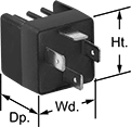
Weatherproof High-Starting-Current Vehicle Relays


Crimp-On
Terminals
An extended housing shields the terminals on these relays from weather. They're also rated IP54—when they're plugged into the relay socket, they're sealed to keep splashing water, like rain, from getting inside. They handle high starting (inrush) currents that often occur when turning on a vehicle. To prevent damage to sensitive equipment, these relays will partially suppress a momentary surge in voltage when the relay switches off. They’ll take a voltage spike of 300V to 500V and bring it down to 100V.
Relays for surface mounting have a tab for added security in high-vibration applications.
![]() For technical drawings and 3-D models, click on a part number.
For technical drawings and 3-D models, click on a part number.
Relays | ||||||||||||||||
|---|---|---|---|---|---|---|---|---|---|---|---|---|---|---|---|---|
Switching Current @ Voltage | Relay Sockets with Crimp-On Terminals | Relay Sockets with Wire Leads | ||||||||||||||
| Number of Terminals | Input Voltage | Off (Normally Open) Circuit Position | On (Normally Closed) Circuit Position | Max. Switching Voltage | Max. Starting Current, A | Control Current, mA | Ht. | Wd. | Dp. | Quick-Disconnect Tab Wd. | Each | Each | Each | |||
For Relay Socket | ||||||||||||||||
1 Circuit Controlled with 1 Off (Normally Open) or 1 On (Normally Closed)—SPDT | ||||||||||||||||
| 5 | 12V DC | 40 A @ 12 V DC | 20 A @ 12 V DC | 18V DC | 150 | 114 | 1.4" | 1.4" | 1.8" | 0.11" | 00000000 | 000000 | 000000 | 00 | 00000000 | 000000 |
| 5 | 12V DC | 40 A @ 12 V DC | 20 A @ 12 V DC | 18V DC | 150 | 155 | 1.4" | 1.4" | 1.8" | 0.25" | 00000000 | 00000 | 0000000 | 000000 | 0000000 | 00000 |
For Relay Socket and Surface Mounting | ||||||||||||||||
1 Circuit Controlled with 1 Off (Normally Open) or 1 On (Normally Closed)—SPDT | ||||||||||||||||
| 5 | 12V DC | 40 A @ 12 V DC | 20 A @ 12 V DC | 18V DC | 150 | 114 | 1.4" | 1.4" | 1.8" | 0.11" | 00000000 | 00000 | 000000 | 00 | 00000000 | 00000 |
| 5 | 12V DC | 40 A @ 12 V DC | 20 A @ 12 V DC | 18V DC | 150 | 138 | 1.4" | 1.4" | 1.8" | 0.25" | 0000000 | 00000 | 0000000 | 00000 | 0000000 | 00000 |
High-Starting-Current Vehicle Relays


Relay Socket and
Surface Mounting


Crimp-On
Terminals
Also known as automotive relays, these relays can handle high starting (inrush) currents.
Relays for surface mounting have a tab for added security in high-vibration applications.
Relays | ||||||||||||||||
|---|---|---|---|---|---|---|---|---|---|---|---|---|---|---|---|---|
Switching Current @ Voltage | Relay Sockets with Crimp-On Terminals | Relay Sockets with Wire Leads | ||||||||||||||
| Number of Terminals | Input Voltage | Off (Normally Open) Circuit Position | On (Normally Closed) Circuit Position | Max. Switching Voltage | Max. Starting Current, A | Control Current, mA | Ht. | Wd. | Dp. | Quick-Disconnect Tab Wd. | Each | Each | Each | |||
For Relay Socket | ||||||||||||||||
1 Circuit Controlled with 1 Off (Normally Open) or 1 On (Normally Closed)—SPDT | ||||||||||||||||
| 5 | 12V DC | 30 A @ 12 V DC | 20 A @ 12 V DC | 18V DC | 150 | 138 | 1.02" | 1.02" | 0.94" | 0.25" | 0000000 | 00000 | 0000000 | 00000 | 0000000 | 000000 |
For Relay Socket and Surface Mounting | ||||||||||||||||
1 Circuit Controlled with 1 Off (Normally Open)—SPST-NO | ||||||||||||||||
| 4 | 12V DC | 50 A @ 12 V DC | __ | 18V DC | 150 | 138 | 1.2" | 1" | 1" | 0.25" and 0.375" | 0000000 | 00000 | 0000000 | 0000 | 0000000 | 00000 |
| 5 | 12V DC | 40 A @ 12 V DC | __ | 20V DC | 150 | 141 | 1" | 1" | 0.9" | 0.25" | 0000000 | 00000 | 0000000 | 0000 | 0000000 | 00000 |
1 Circuit Controlled with 1 Off (Normally Open) or 1 On (Normally Closed)—SPDT | ||||||||||||||||
| 5 | 12V DC | 30 A @ 12 V DC | 20 A @ 12 V DC | 18V DC | 150 | 138 | 1.1" | 1.1" | 1" | 0.25" | 0000000 | 0000 | 0000000 | 0000 | 0000000 | 00000 |
Solid State High-Starting-Current Vehicle Relays
Crimp-On
Terminals
With no moving parts, these solid state relays require less maintenance and last longer, switch faster, and are quieter than mechanical relays. They can handle high starting (inrush) currents. The blade terminals meet ISO 8092-1 dimensions, ensuring they are compatible with the electrical connections in road vehicles you need to maintain or repair. Also known as ISO relays or automotive relays.
Relays | Relay Sockets with Crimp-On Terminals | Relay Sockets with Wire Leads | |||||||||||||
|---|---|---|---|---|---|---|---|---|---|---|---|---|---|---|---|
| Number of Terminals | Input Voltage | Switching Current @ 12V DC | Max. Switching Voltage | Max. Starting Current, A | Control Current, mA | Ht. | Wd. | Dp. | Quick-Disconnect Tab Wd. | Each | Each | Each | |||
1 Circuit Controlled with 1 Off (Normally Open)—SPST-NO | |||||||||||||||
| 4 | 12V DC | 20A | 16V DC | 80 | 10 | 1.1" | 1.1" | 1" | 0.25" | 0000000 | 000000 | 0000000 | 00000 | 0000000 | 000000 |