


About Timer Relays
More
About Motor Switches and Starters
More
Choosing an Electrical Switch
More
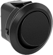
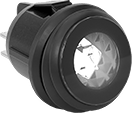
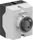
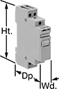
High-Current Toggle Switches

Able to withstand high currents, these switches are often used with motors and pumps.
![]() For technical drawings and 3-D models, click on a part number.
For technical drawings and 3-D models, click on a part number.
| No. of Circuits Controlled | Switch Starting Position | Switch Action | No. of Terminals | Industry Designation | Position Designation | Switching Current @ Voltage | Max. Voltage | Dp. Behind Panel | Mounting Hardware Included | Each | |
2 Position with Screw Terminals | |||||||||||
|---|---|---|---|---|---|---|---|---|---|---|---|
For 1/2" Panel Cutout Dia. | |||||||||||
| 1 | 1 Off (Normally Open) | Stays Switched (Maintained) | 2 | SPST-NO | On-Off | 16 A @ 125 V AC, 8 A @ 30 V DC | 250V DC 250V AC | 0.77" | Yes | 0000000 | 000000 |
| 2 | 2 Off (Normally Open) | Stays Switched (Maintained) | 4 | DPST-NO | On-Off | 16 A @ 125 V AC, 8 A @ 30 V DC | 250V DC 250V AC | 0.77" | Yes | 0000000 | 00000 |
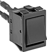
Rocker Switches
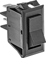
The wide surface of these switches makes them easy to press on and off, even if your hands are full and you need to use an elbow. They’re often used as power switches on electronic devices and control panels.
Switches for a 13/16” dia. panel cutout are round, so you can use a drill bit or knockout to install them instead of cutting a rectangular hole.
Illuminated switches are easy to see in dim and dark areas. They come in red and green, so you can color code your set up.
Switches with an on-on position designation alternate power between sets of terminals.
Note: Illuminated switches include a bulb. If wiring the switch and the bulb to the same circuit, the circuit voltage must not exceed the bulb voltage.
![]() For technical drawings and 3-D models, click on a part number.
For technical drawings and 3-D models, click on a part number.
| No. of Circuits Controlled | Switch Starting Position | Switch Action | No. of Terminals | Industry Designation | Position Designation | Switching Current @ Voltage | Max. Voltage | Bulb Voltage | Quick-Disconnect Tab Wd. | Choose a Color | Each | ||
2 Position with Quick-Disconnect Terminals | |||||||||||||
|---|---|---|---|---|---|---|---|---|---|---|---|---|---|
For 13/16" Dia. Panel Cutout | |||||||||||||
| A | 1 | 1 Off (Normally Open) | Stays Switched (Maintained) | 2 | SPST-NO | On-On | 16 A @ 125 V AC, 10 A @ 250 V AC | 250V AC | __ | 0.189" | Black | 00000000 | 00000 |
| A | 1 | 1 On (Normally Closed) | Stays Switched (Maintained) | 2 | SPST-NC | On-Off | 16 A @ 125 V AC, 10 A @ 250 V AC | 250V AC | __ | 0.189" | Black | 00000000 | 0000 |
| B | 2 | 2 Off (Normally Open) | Stays Switched (Maintained) | 4 | DPST-NO | On-Off | 16 A @ 125 V AC, 10 A @ 250 V AC | 250V AC | __ | 0.189" | Black | 00000000 | 0000 |
| B | 2 | 2 Off (Normally Open) or 2 On (Normally Closed) | Stays Switched (Maintained) | 6 | DPDT | On-On | 16 A @ 125 V AC, 10 A @ 250 V AC | 250V AC | __ | 0.189" | Black | 00000000 | 00000 |
For 1 1/8" Ht.×9/16" Wd. Panel Cutout | |||||||||||||
| C | 1 | 1 Off (Normally Open) | Stays Switched (Maintained) | 2 | SPST-NO | On-Off | 16 A @ 125 V AC | 250V AC | __ | 0.25" | Black | 0000000 | 0000 |
| C | 1 | 1 Off (Normally Open) or 1 On (Normally Closed) | Stays Switched (Maintained) | 3 | SPDT | On-On | 16 A @ 125 V AC | 250V AC | __ | 0.25" | Black | 0000000 | 0000 |
For 1 3/16" Ht.×7/16" Wd. Panel Cutout | |||||||||||||
| C | 1 | 1 Off (Normally Open) | Stays Switched (Maintained) | 2 | SPST-NO | On-Off | 20 A @ 125 V AC, 16 A @ 250 V AC | 250V AC | __ | 0.25" | Black | 00000000 | 0000 |
| C | 1 | 1 Off (Normally Open) or 1 On (Normally Closed) | Stays Switched (Maintained) | 3 | SPDT | On-On | 20 A @ 125 V AC, 16 A @ 250 V AC | 250V AC | __ | 0.25" | Black | 00000000 | 0000 |
For 1 3/16" Ht.×7/8" Wd. Panel Cutout | |||||||||||||
| C | 2 | 2 Off (Normally Open) | Stays Switched (Maintained) | 4 | DPST-NO | On-Off | 16 A @ 125 V AC | 250V AC | __ | 0.25" | Black | 0000000 | 00000 |
| C | 2 | 2 Off (Normally Open) | Stays Switched (Maintained) | 4 | DPST-NO | On-Off | 20 A @ 125 V AC, 16 A @ 250 V AC | 250V AC | __ | 0.25" | Black | 00000000 | 0000 |
| C | 2 | 2 Off (Normally Open) or 2 On (Normally Closed) | Stays Switched (Maintained) | 6 | DPDT | On-On | 16 A @ 125 V AC | 250V AC | __ | 0.25" | Black | 0000000 | 0000 |
| C | 2 | 2 Off (Normally Open) or 2 On (Normally Closed) | Stays Switched (Maintained) | 6 | DPDT | On-On | 20 A @ 125 V AC, 16 A @ 250 V AC | 250V AC | __ | 0.25" | Black | 00000000 | 0000 |
2 Position with Quick-Disconnect Terminals—Illuminated | |||||||||||||
For 13/16" Dia. Panel Cutout | |||||||||||||
| D | 1 | 1 On (Normally Closed) | Stays Switched (Maintained) | 2 | SPST-NC | On-Off | 16 A @ 125 V AC, 10 A @ 250 V AC | 250V AC | 125V AC | 0.25" | 00000000 | 0000 | |
| E | 2 | 2 Off (Normally Open) | Stays Switched (Maintained) | 4 | DPST-NO | On-Off | 16 A @ 125 V AC, 10 A @ 250 V AC | 250V AC | 110V AC | 0.189" | 00000000 | 00000 | |
3 Position with Quick-Disconnect Terminals | |||||||||||||
For 13/16" Dia. Panel Cutout | |||||||||||||
| A | 1 | 1 Off (Normally Open) | Stays Switched (Maintained) | 2 | SPST-NO | On-Off-On | 16 A @ 125 V AC, 10 A @ 250 V AC | 250V AC | __ | 0.189" | Black | 00000000 | 0000 |
| B | 2 | 2 Off (Normally Open) or 2 On (Normally Closed) | Stays Switched (Maintained) | 6 | DPDT | On-Off-On | 16 A @ 125 V AC, 10 A @ 250 V AC | 250V AC | __ | 0.189" | Black | 00000000 | 00000 |
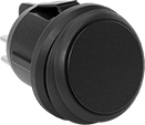
Submersible High-Starting-Current Rocker Switches


Rated IP67 for protection from dust and temporary submersion. Also known as high-inrush current switches, these switches can handle starting currents up to 10 times greater than their current rating, such as when a motor starts. They're often used with amplifiers, power supplies, and other high-starting-current devices. Easy to press, these switches have a wide, flat actuation area. Color-code your switches so that operators can identify their function at a glance.
![]() For technical drawings and 3-D models, click on a part number.
For technical drawings and 3-D models, click on a part number.
| No. of Circuits Controlled | Switch Starting Position | Switch Action | No. of Terminals | Industry Designation | Position Designation | Message (Location) | Switching Current @ Voltage | Max. Voltage | Quick-Disconnect Tab Wd. | Choose a Color | Each | |
2 Position with Quick-Disconnect Terminals | ||||||||||||
|---|---|---|---|---|---|---|---|---|---|---|---|---|
For 1 7/32" Ht. × 13/16" Wd. Panel Cutout | ||||||||||||
| 2 | 2 Off (Normally Open) | Stays Switched (Maintained) | 4 | DPST-NO | On-Off | Horizontal Line (Top), Circle (Bottom) | 16 A @ 125 V AC | 250V AC | 0.187" | 00000000 | 000000 | |
| 2 | 2 Off (Normally Open) or 2 On (Normally Closed) | Stays Switched (Maintained) | 6 | DPDT | On-On | Blank (Top), Blank (Bottom) | 16 A @ 125 V AC | 250V AC | 0.187" | 00000000 | 00000 | |
High-Starting-Current Rocker Switches


Line/Circle
with Wire Leads
Also known as high-inrush current switches, these switches can handle starting currents up to 10 times greater than their current rating, such as when a motor starts. They're often used with amplifiers, power supplies, and other high-starting-current devices.
Switches with an on-on position designation alternate power between sets of terminals.
![]() For technical drawings and 3-D models, click on a part number.
For technical drawings and 3-D models, click on a part number.
Wire Leads | |||||||||||||
|---|---|---|---|---|---|---|---|---|---|---|---|---|---|
| No. of Circuits Controlled | Switch Starting Position | Switch Action | No. of Terminals | Industry Designation | Position Designation | Message (Location) | Switching Current @ Voltage | Max. Voltage | No. of | Lg. | Choose a Color | Each | |
2 Position with Tab Terminals | |||||||||||||
For 1 3/16"×13/16" Wd. Panel Cutout | |||||||||||||
| 1 | 1 Off (Normally Open) | Stays Switched (Maintained) | 2 | SPST-NO | On-Off | Blank (Top), Blank (Bottom) | 16 A @ 125 V AC, 5 A @ 30 V DC | 72V DC 250V AC | __ | __ | 0000000 | 000000 | |
| 1 | 1 Off (Normally Open) | Stays Switched (Maintained) | 2 | SPST-NO | On-Off | Horizontal Line (Top), Circle (Bottom) | 16 A @ 125 V AC, 5 A @ 30 V DC | 72V DC 250V AC | __ | __ | 0000000 | 00000 | |
| 1 | 1 Off (Normally Open) | Stays Switched (Maintained) | 2 | SPST-NO | On-Off | Vertical Line (Top), Circle (Bottom) | 16 A @ 125 V AC, 5 A @ 30 V DC | 72V DC 250V AC | __ | __ | 0000000 | 00000 | |
| 1 | 1 Off (Normally Open) or 1 On (Normally Closed) | Stays Switched (Maintained) | 3 | SPDT | On-On | Blank (Top), Blank (Bottom) | 16 A @ 125 V AC, 5 A @ 30 V DC | 72V DC 250V AC | __ | __ | 0000000 | 00000 | |
| 2 | 2 Off (Normally Open) | Stays Switched (Maintained) | 4 | DPST-NO | On-Off | Blank (Top), Blank (Bottom) | 16 A @ 125 V AC, 5 A @ 30 V DC | 72V DC 250V AC | __ | __ | 0000000 | 00000 | |
| 2 | 2 Off (Normally Open) | Stays Switched (Maintained) | 4 | DPST-NO | On-Off | Horizontal Line (Top), Circle (Bottom) | 16 A @ 125 V AC, 5 A @ 30 V DC | 72V DC 250V AC | __ | __ | 0000000 | 00000 | |
| 2 | 2 Off (Normally Open) | Stays Switched (Maintained) | 4 | DPST-NO | On-Off | Vertical Line (Top), Circle (Bottom) | 16 A @ 125 V AC, 5 A @ 30 V DC | 72V DC 250V AC | __ | __ | 0000000 | 00000 | |
| 2 | 2 Off (Normally Open) or 2 On (Normally Closed) | Stays Switched (Maintained) | 6 | DPDT | On-On | Blank (Top), Blank (Bottom) | 16 A @ 125 V AC, 5 A @ 30 V DC | 72V DC 250V AC | __ | __ | 0000000 | 00000 | |
2 Position with Wire Leads | |||||||||||||
For 1 3/16"×13/16" Wd. Panel Cutout | |||||||||||||
| 1 | 1 Off (Normally Open) | Stays Switched (Maintained) | 2 | SPST-NO | On-Off | Blank (Top), Blank (Bottom) | 16 A @ 120 V AC, 5 A @ 24 V DC | 72V DC 250V AC | 2 | 12" | 0000000 | 00000 | |
| 1 | 1 Off (Normally Open) | Stays Switched (Maintained) | 2 | SPST-NO | On-Off | Horizontal Line (Top), Circle (Bottom) | 16 A @ 120 V AC, 5 A @ 24 V DC | 72V DC 250V AC | 2 | 12" | Black | 0000000 | 00000 |
| 1 | 1 Off (Normally Open) | Stays Switched (Maintained) | 2 | SPST-NO | On-Off | Vertical Line (Top), Circle (Bottom) | 16 A @ 120 V AC, 5 A @ 24 V DC | 72V DC 250V AC | 2 | 12" | 0000000 | 00000 | |
| 2 | 2 Off (Normally Open) | Stays Switched (Maintained) | 4 | DPST-NO | On-Off | Blank (Top), Blank (Bottom) | 16 A @ 120 V AC, 5 A @ 24 V DC | 72V DC 250V AC | 4 | 12" | Black | 0000000 | 00000 |
| 2 | 2 Off (Normally Open) | Stays Switched (Maintained) | 4 | DPST-NO | On-Off | Horizontal Line (Top), Circle (Bottom) | 16 A @ 120 V AC, 5 A @ 24 V DC | 72V DC 250V AC | 4 | 12" | 0000000 | 00000 | |
| 2 | 2 Off (Normally Open) | Stays Switched (Maintained) | 4 | DPST-NO | On-Off | Vertical Line (Top), Circle (Bottom) | 16 A @ 120 V AC, 5 A @ 24 V DC | 72V DC 250V AC | 4 | 12" | Black | 0000000 | 00000 |
| 2 | 2 Off (Normally Open) or 2 On (Normally Closed) | Stays Switched (Maintained) | 6 | DPDT | On-On | Blank (Top), Blank (Bottom) | 16 A @ 120 V AC, 5 A @ 24 V DC | 72V DC 250V AC | 6 | 12" | Black | 0000000 | 00000 |
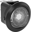
Corrosion-Resistant Washdown Foot Switches
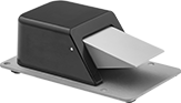
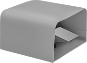
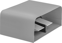
Step on these switches to actuate a process hands-free in an area with frequent washdowns. Rated NEMA 6P, 13, and IP68, they protect against corrosion, washdowns, temporary submersion, and oil/coolant spraying. Made of aluminum, they resist corrosion better than iron and steel switches.
Switches without a guard let you easily see the pedal and step on it from many angles.
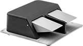
Switches with a guard shield the pedal from getting accidentally pressed down.
Switches | |||||||||||||||
|---|---|---|---|---|---|---|---|---|---|---|---|---|---|---|---|
Mounting | Replacement Foot Pedals | ||||||||||||||
| No. of Circuits Controlled | Switch Starting Position | Switch Action | Industry Designation | Switching Current @ Voltage | No. of Terminals | Quick-Disconnect Tab Wd. | Conduit Trade Size | Fasteners Included | No. of Holes | Hole Dia. | Each | Each | |||
1 Speed with Quick-Disconnect Terminals | |||||||||||||||
Aluminum Housing | |||||||||||||||
| C | 1 | 1 Off (Normally Open) or 1 On (Normally Closed) | Springs Back (Momentary) | SPDT | 16 A @ 125 V AC/250 V AC | 3 | 0.187" | 1/2 | No | 4 | 0.28" | 0000000 | 0000000 | 0000000 | 00000 |
| C | 2 | 2 Off (Normally Open) or 2 On (Normally Closed) | Springs Back (Momentary) | DPDT | 16 A @ 125 V AC/250 V AC | 6 | 0.187" | 1/2 | No | 4 | 0.28" | 0000000 | 000000 | 0000000 | 0000 |
| D | 2 | 1 Off (Normally Open) or 1 On (Normally Closed) | Springs Back (Momentary) | SPDT | 16 A @ 125 V AC/250 V AC | 6 | 0.187" | 3/4 | No | 4 | 0.28" | 0000000 | 000000 | 0000000 | 0000 |
| D | 4 | 2 Off (Normally Open) or 2 On (Normally Closed) | Springs Back (Momentary) | DPDT | 16 A @ 125 V AC/250 V AC | 12 | 0.187" | 3/4 | No | 4 | 0.28" | 0000000 | 000000 | 0000000 | 0000 |
Aluminum Housing with Steel Guard | |||||||||||||||
| E | 1 | 1 Off (Normally Open) or 1 On (Normally Closed) | Springs Back (Momentary) | SPDT | 16 A @ 125 V AC/250 V AC | 3 | 0.187" | 1/2 | No | 4 | 0.28" | 0000000 | 000000 | 0000000 | 0000 |
| E | 2 | 2 Off (Normally Open) or 2 On (Normally Closed) | Springs Back (Momentary) | DPDT | 16 A @ 125 V AC/250 V AC | 6 | 0.187" | 1/2 | No | 4 | 0.28" | 0000000 | 000000 | 0000000 | 0000 |
| F | 2 | 1 Off (Normally Open) or 1 On (Normally Closed) | Springs Back (Momentary) | SPDT | 16 A @ 125 V AC/250 V AC | 6 | 0.187" | 3/4 | No | 4 | 0.28" | 0000000 | 000000 | 0000000 | 0000 |
| F | 4 | 2 Off (Normally Open) or 2 On (Normally Closed) | Springs Back (Momentary) | DPDT | 16 A @ 125 V AC/250 V AC | 12 | 0.187" | 3/4 | No | 4 | 0.28" | 0000000 | 000000 | 0000000 | 0000 |
Smart Time and Day Activated Switches
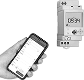
Use your smart phone to turn equipment on and off at a set time and day. These switches connect to your phone via NFC (near field communication) and work with a free app to set schedules, adjust settings, and save programs. They can perform a different program each day of the week, and they compensate for leap year and daylight savings time. You can remotely apply programs across compatible switches, so it’s easy to reprogram lighting or equipment in large facilities. These switches mount to a flat surface or attach to DIN rail.
Switches with astronomical timing can be set to turn lights on and off based on sunrise and sunset.
| No. of Circuits Controlled | Switching Current @ Voltage | Input Voltage | Maximum On/Off Cycles | Minimum Set Time | Timing Adjustment Style | Industry Designation | Ht. | Wd. | Dp. | Connection Type | Operating System Compatibility | For DIN Rail Ht., mm | Wire Connection Type | Each | |
7-Day Timing Cycle | |||||||||||||||
|---|---|---|---|---|---|---|---|---|---|---|---|---|---|---|---|
| 1 | 16 A @ 240 V AC | 120V AC/208V AC/240V AC/120V DC/240V DC | 50 per Week | 1 min. | Joystick | SPDT | 3.4" | 1.4" | 2.2" | NFC | Android 5.1 or Later, iOS 13.1 or Later | 35 | Screw Terminals | 00000000 | 0000000 |
| 2 | 16 A @ 240 V AC | 120V AC/208V AC/240V AC/120V DC/240V DC | 50 per Week | 1 min. | Joystick | DPDT | 3.4" | 1.4" | 2.2" | NFC | Android 5.1 or Later, iOS 13.1 or Later | 35 | Screw Terminals | 00000000 | 000000 |
7-Day Timing Cycle with Astronomical Timing | |||||||||||||||
| 1 | 16 A @ 240 V AC | 120V AC/208V AC/240V AC/120V DC/240V DC | 50 per Week | 1 min. | Joystick | SPDT | 3.4" | 1.4" | 2.2" | NFC | Android 5.1 or Later, iOS 13.1 or Later | 35 | Screw Terminals | 00000000 | 000000 |
| 2 | 16 A @ 240 V AC | 120V AC/208V AC/240V AC/120V DC/240V DC | 50 per Week | 1 min. | Joystick | DPDT | 3.4" | 1.4" | 2.2" | NFC | Android 5.1 or Later, iOS 13.1 or Later | 35 | Screw Terminals | 00000000 | 000000 |
Energy-Saving Motor Starters
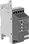
Save electricity and extend motor life by reducing the motor's starting current. These starters gradually start and stop motors. Use them on motors where torque varies, such as pumps, compressors, and conveyors. All have an auxiliary contact to send a signal or connect to another device, such as an alarm or indicating light.
![]() For technical drawings and 3-D models, click on a part number.
For technical drawings and 3-D models, click on a part number.
Switching | Time, sec. | |||||||||||
|---|---|---|---|---|---|---|---|---|---|---|---|---|
| Full Load Current, A | Input Voltage | Voltage | Current | Electrical Phase (hp) | Acceleration | Deceleration | Ht. | Wd. | Mount. Location | For DIN Rail Ht., mm | Each | |
Motor Starters with 1 Auxiliary Contact—1 Off (Normally Open) | ||||||||||||
| 15 | 24V DC | 208-600V AC | 16A | Three (5 hp @ 240 V AC) Three (10 hp @ 480 V AC) | 1-20 | 0-20 | 5.5" | 1.8" | DIN Rail, Surface | 35 | 0000000 | 0000000 |
Panel-Mount Compact Disconnect Switches

Install these switches in a panel cutout. Small enough to fit in tight spaces, they handle comparable electrical loads to standard sized switches. They cut power and keep it isolated to prevent equipment from starting up during inspection and maintenance. All have a lockout so you can secure them in the off position with a padlock (not included). They’re rated IP65 for protection from washdowns.
![]() For technical drawings and 3-D models, click on a part number.
For technical drawings and 3-D models, click on a part number.
| Switching Current @ Voltage | Industry Designation | Electrical Phase (hp) | Ht. | Wd. | Dp. Behind Panel | Specifications Met | Each | |
Gray Plastic Housing with Black Actuator | ||||||||
|---|---|---|---|---|---|---|---|---|
Stays Switched (Maintained) | ||||||||
3 Circuits with Lockout—For 3/8" Panel Cutout Dia. | ||||||||
| 12 A @ 600 V AC, 16 A @ 24 V DC | 3PST | Single (1/2 hp @ 120 V AC) Three (1 hp @ 120 V AC) Three (3 hp @ 240 V AC) | 3 1/4" | 2 1/2" | 1 13/16" | UL Recognized Component, UL 508 | 000000000 | 000000 |
| 16 A @ 600 V AC, 20 A @ 24 V DC | 3PST | Single (1 hp @ 120 V AC) Three (2 hp @ 120 V AC) Three (5 hp @ 240 V AC) | 3 1/4" | 2 1/2" | 1 13/16" | UL Recognized Component, UL 508 | 000000000 | 00000 |
4 Circuits with Lockout—For 3/8" Panel Cutout Dia. | ||||||||
| 12 A @ 600 V AC, 16 A @ 24 V DC | 4PST | Single (1/2 hp @ 120 V AC) Three (1 hp @ 120 V AC) Three (3 hp @ 240 V AC) | 3 1/4" | 2 1/2" | 1 13/16" | UL Recognized Component, UL 508 | 000000000 | 00000 |
| 16 A @ 600 V AC, 20 A @ 24 V DC | 4PST | Single (1 hp @ 120 V AC) Three (2 hp @ 120 V AC) Three (5 hp @ 240 V AC) | 3 1/4" | 2 1/2" | 1 13/16" | UL Recognized Component, UL 508 | 000000000 | 00000 |
Yellow Plastic Housing with Red Actuator | ||||||||
Stays Switched (Maintained) | ||||||||
3 Circuits with Lockout—For 3/8" Panel Cutout Dia. | ||||||||
| 12 A @ 600 V AC, 16 A @ 24 V DC | 3PST | Single (1/2 hp @ 120 V AC) Three (1 hp @ 120 V AC) Three (3 hp @ 240 V AC) | 3 1/4" | 2 1/2" | 1 13/16" | UL Recognized Component, UL 508 | 00000000 | 00000 |
| 16 A @ 600 V AC, 20 A @ 24 V DC | 3PST | Single (1 hp @ 120 V AC) Three (2 hp @ 120 V AC) Three (5 hp @ 240 V AC) | 3 1/4" | 2 1/2" | 1 13/16" | UL Recognized Component, UL 508 | 00000000 | 00000 |
4 Circuits with Lockout—For 3/8" Panel Cutout Dia. | ||||||||
| 12 A @ 600 V AC, 16 A @ 24 V DC | 4PST | Single (1/2 hp @ 120 V AC) Three (1 hp @ 120 V AC) Three (3 hp @ 240 V AC) | 3 1/4" | 2 1/2" | 1 13/16" | UL Recognized Component, UL 508 | 00000000 | 00000 |
| 16 A @ 600 V AC, 20 A @ 24 V DC | 4PST | Single (1 hp @ 120 V AC) Three (2 hp @ 120 V AC) Three (5 hp @ 240 V AC) | 3 1/4" | 2 1/2" | 1 13/16" | UL Recognized Component, UL 508 | 00000000 | 00000 |
Enclosed Compact Disconnect Switches
Small yet mighty, these switches are about as tall and wide as an index card yet durable enough to mount directly to a wall. Their polycarbonate housing protects the switch and resists denting, chipping, and cracking. Rated IP65, the housing also seals out water even in frequently washed down areas. Don’t be fooled by their size—these switches can handle electrical loads comparable to a standard sized switch.
These switches cut power and keep it isolated to prevent equipment from starting up during inspection and maintenance. All have a lockout, so you can secure them in the off position with a padlock (not included).
![]() For technical drawings and 3-D models, click on a part number.
For technical drawings and 3-D models, click on a part number.
Yellow Plastic Housing with Red Actuator | ||||||||
|---|---|---|---|---|---|---|---|---|
| Switching Current @ Voltage | Industry Designation | Electrical Phase (hp) | Ht. | Wd. | Environmental Rating | Specifications Met | Each | |
Stays Switched (Maintained) | ||||||||
3 Circuits with Lockout | ||||||||
| 12 A @ 600 V AC, 16 A @ 24 V DC | 3PST | Single (1/2 hp @ 120 V AC) Three (1 hp @ 120 V AC) Three (3 hp @ 240 V AC) | 4 3/4" | 3 13/16" | IP65 | UL Recognized Component, CSA Certified, UL 508 | 00000000 | 0000000 |
| 16 A @ 600 V AC, 20 A @ 24 V DC | 3PST | Single (1 hp @ 120 V AC) Three (2 hp @ 120 V AC) Three (5 hp @ 240 V AC) | 4 3/4" | 3 13/16" | IP65 | UL Recognized Component, CSA Certified, UL 508 | 00000000 | 000000 |
4 Circuits with Lockout | ||||||||
| 12 A @ 600 V AC, 16 A @ 24 V DC | 4PST | Single (1/2 hp @ 120 V AC) Three (1 hp @ 120 V AC) Three (3 hp @ 240 V AC) | 4 3/4" | 3 13/16" | IP65 | UL Recognized Component, CSA Certified | 00000000 | 000000 |
| 16 A @ 600 V AC, 20 A @ 24 V DC | 4PST | Single (1 hp @ 120 V AC) Three (2 hp @ 120 V AC) Three (5 hp @ 240 V AC) | 4 3/4" | 3 13/16" | IP65 | UL Recognized Component, CSA Certified | 00000000 | 000000 |
DIN-Rail Mount Interface Relays
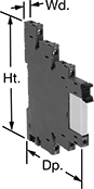
Prevent damage from voltage spikes, reduce signal interference, and amplify signal with these relays, which interface between your controller and components to isolate input and output circuits. They mount on 35 mm DIN rail (also known as DIN 3 rail) for fast installation.
![]() For technical drawings and 3-D models, click on a part number.
For technical drawings and 3-D models, click on a part number.
Relays with Relay Sockets | Replacement Relays | ||||||||||
|---|---|---|---|---|---|---|---|---|---|---|---|
| Number of Terminals | Input Voltage | Control Current, mA | Switching Current @ 240V AC | hp @ Switching Voltage | Ht. | Wd. | Dp. | Each | Each | ||
1 Circuit Controlled with 1 Off (Normally Open) or 1 On (Normally Closed)—SPDT | |||||||||||
With Screw-Clamp Terminals | |||||||||||
| 5 | 24V AC | 45 | 16A | 1/3 hp @ 120 V AC | 3.3" | 0.6" | 2.7" | 0000000 | 000000 | 0000000 | 000000 |
| 5 | 120V AC | 8 | 16A | 1/3 hp @ 120 V AC | 3.3" | 0.6" | 2.7" | 0000000 | 00000 | 0000000 | 00000 |
| 5 | 240V AC | 3.5 | 16A | 1/4 hp @ 120 V AC | 3.5" | 0.6" | 3" | 0000000 | 00000 | 0000000 | 0000 |
| 5 | 12V DC | 41 | 16A | 1/4 hp @ 120 V AC | 3.5" | 0.6" | 3" | 0000000 | 00000 | 0000000 | 0000 |
| 5 | 24V DC | 20 | 16A | 1/3 hp @ 120 V AC | 3.3" | 0.6" | 2.7" | 0000000 | 00000 | 0000000 | 0000 |
Circuit Board Relays
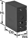
Smaller than relays with electrical wiring, these relays fit in compact devices. Mount them through holes on circuit boards with their solder pin terminals. Use them to control heaters, fans, and other high-power components from a low-power circuit.
![]() For technical drawings and 3-D models, click on a part number.
For technical drawings and 3-D models, click on a part number.
| Number of Terminals | Input Voltage | Control Current, mA | Switching Current @ Voltage | Max. Switching Voltage | Mechanical Life Cycles | Ht. | Wd. | Dp. | Pin Lg. | Each | |
Mechanical | |||||||||||
|---|---|---|---|---|---|---|---|---|---|---|---|
1 Circuit Controlled with 1 Off (Normally Open) or 1 On (Normally Closed)—SPDT | |||||||||||
| 8 | 12V DC | 33 | 16 A @ 240 V AC | 250V AC | 10,000,000 | 1.1" | 0.5" | 0.6" | 0.1" | 0000000 | 00000 |
| 8 | 110V DC | 4.5 | 16 A @ 240 V AC | 250V AC | 10,000,000 | 1.1" | 0.5" | 0.6" | 0.1" | 0000000 | 0000 |
Hazardous Location Relays
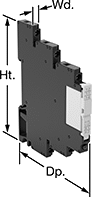
Sealed for safety, these relays are a good choice for hazardous locations where combustible or corrosive gases may be present.
Relays with screw terminals or spring-clamp terminals are considered interface relays, so they’re placed between your controller and components to isolate the input and output circuits. This means they protect your component from voltage spikes while amplifying the relay’s signal and reducing interference for reliable transmission. They are often used for switching applications, such as small motors and pilot lights. The included relay socket mounts on 35 mm DIN rail (also known as DIN 3 rail).
![]() For technical drawings and 3-D models, click on a part number.
For technical drawings and 3-D models, click on a part number.
| Number of Terminals | Input Voltage | Control Current, mA | Switching Current @ Voltage | Max. Switching Voltage | Ht. | Wd. | Dp. | Environmental Rating | Each | |
Screw Terminals | ||||||||||
|---|---|---|---|---|---|---|---|---|---|---|
1 Circuit Controlled with 1 Off (Normally Open) or 1 On (Normally Closed)—SPDT | ||||||||||
| 5 | 24V AC, 24V DC | 13.5 | 16 A @ 240 V AC/24 V DC | 400V AC/300V DC | 3.5" | 0.6" | 2.9" | IP20; NEC Class I Division 2 Groups A, B, C, D | 0000000 | 000000 |
| 5 | 48V AC, 48V DC | 4 | 16 A @ 240 V AC/24 V DC | 400V AC/300V DC | 3.5" | 0.6" | 2.9" | IP20; NEC Class I Division 2 Groups A, B, C, D | 0000000 | 00000 |
| 5 | 120V AC, 120V DC | 3.5 | 16 A @ 240 V AC/24 V DC | 400V AC/300V DC | 3.5" | 0.6" | 2.9" | IP20; NEC Class I Division 2 Groups A, B, C, D | 0000000 | 00000 |
| 5 | 240V AC, 240V DC | 3.5 | 16 A @ 240 V AC/24 V DC | 400V AC/300V DC | 3.5" | 0.6" | 2.9" | IP20; NEC Class I Division 2 Groups A, B, C, D | 0000000 | 00000 |
Sequenced Latching Relays
These relays switch through a series of different circuit configurations every time they receive an input voltage. The input voltage latches them in position, so they don’t require a constant voltage to stay switched. Use them to control motors, pumps, and lighting. The covered terminals prevent contact with live connections. Mount to 35 mm DIN rail. Also known as step relays.
![]() For technical drawings and 3-D models, click on a part number.
For technical drawings and 3-D models, click on a part number.
| Switch Starting Position | Input Voltage | Control Power | Switching Current @ 120V AC | Max. Switching Voltage | hp @ Switching Voltage | Ht. | Wd. | Dp. | Each | |
1 Circuit Controlled—SPST-NO | ||||||||||
|---|---|---|---|---|---|---|---|---|---|---|
With 4 Terminals | ||||||||||
| 1st Signal—1 Off (Normally Open) 2nd Signal—1 On (Normally Closed) | 24V AC | 6.5VA | 16A | 277V AC | 1/2 hp @ 120 V AC | 3.3" | 0.7" | 2.4" | 00000000 | 000000 |
| 1st Signal—1 Off (Normally Open) 2nd Signal—1 On (Normally Closed) | 120V AC | 6.5VA | 16A | 277V AC | 1/2 hp @ 120 V AC | 3.3" | 0.7" | 2.4" | 00000000 | 00000 |
| 1st Signal—1 Off (Normally Open) 2nd Signal—1 On (Normally Closed) | 240V AC | 6.5VA | 16A | 277V AC | 1/2 hp @ 120 V AC | 3.3" | 0.7" | 2.4" | 00000000 | 00000 |
| 1st Signal—1 Off (Normally Open) 2nd Signal—1 On (Normally Closed) | 12V DC | 5W | 16A | 277V AC | 1/2 hp @ 120 V AC | 3.3" | 0.7" | 2.4" | 00000000 | 00000 |
| 1st Signal—1 Off (Normally Open) 2nd Signal—1 On (Normally Closed) | 24V DC | 5W | 16A | 277V AC | 1/2 hp @ 120 V AC | 3.3" | 0.7" | 2.4" | 00000000 | 00000 |
2 Circuits Controlled—DPST-1NO/1NC | ||||||||||
With 6 Terminals | ||||||||||
| 1st Signal—1 Off (Normally Open) and 1 On (Normally Closed) 2nd Signal—1 On (Normally Closed) and 1 Off (Normally Open) | 24V AC | 6.5VA | 16A | 277V AC | 1/2 hp @ 120 V AC | 3.3" | 0.7" | 2.4" | 00000000 | 00000 |
| 1st Signal—1 Off (Normally Open) and 1 On (Normally Closed) 2nd Signal—1 On (Normally Closed) and 1 Off (Normally Open) | 120V AC | 6.5VA | 16A | 277V AC | 1/2 hp @ 120 V AC | 3.3" | 0.7" | 2.4" | 00000000 | 00000 |
| 1st Signal—1 Off (Normally Open) and 1 On (Normally Closed) 2nd Signal—1 On (Normally Closed) and 1 Off (Normally Open) | 240V AC | 6.5VA | 16A | 277V AC | 1/2 hp @ 120 V AC | 3.3" | 0.7" | 2.4" | 00000000 | 00000 |
| 1st Signal—1 Off (Normally Open) and 1 On (Normally Closed) 2nd Signal—1 On (Normally Closed) and 1 Off (Normally Open) | 12V DC | 5W | 16A | 277V AC | 1/2 hp @ 120 V AC | 3.3" | 0.7" | 2.4" | 00000000 | 00000 |
| 1st Signal—1 Off (Normally Open) and 1 On (Normally Closed) 2nd Signal—1 On (Normally Closed) and 1 Off (Normally Open) | 24V DC | 5W | 16A | 277V AC | 1/2 hp @ 120 V AC | 3.3" | 0.7" | 2.4" | 00000000 | 00000 |
2 Circuits Controlled—DPST-NO | ||||||||||
With 6 Terminals | ||||||||||
| 1st Signal—2 Off (Normally Open) 2nd Signal—2 On (Normally Closed) | 24V AC | 6.5VA | 16A | 277V AC | 1/2 hp @ 120 V AC | 3.3" | 0.7" | 2.4" | 00000000 | 00000 |
| 1st Signal—2 Off (Normally Open) 2nd Signal—2 On (Normally Closed) | 120V AC | 6.5VA | 16A | 277V AC | 1/2 hp @ 120 V AC | 3.3" | 0.7" | 2.4" | 00000000 | 00000 |
| 1st Signal—2 Off (Normally Open) 2nd Signal—2 On (Normally Closed) | 240V AC | 6.5VA | 16A | 277V AC | 1/2 hp @ 120 V AC | 3.3" | 0.7" | 2.4" | 00000000 | 00000 |
| 1st Signal—2 Off (Normally Open) 2nd Signal—2 On (Normally Closed) | 12V DC | 5W | 16A | 277V AC | 1/2 hp @ 120 V AC | 3.3" | 0.7" | 2.4" | 00000000 | 00000 |
| 1st Signal—2 Off (Normally Open) 2nd Signal—2 On (Normally Closed) | 24V DC | 5W | 16A | 277V AC | 1/2 hp @ 120 V AC | 3.3" | 0.7" | 2.4" | 00000000 | 00000 |
| 1st Signal—2 Off (Normally Open) 2nd Signal—1 On (Normally Closed) and 1 Off (Normally Open) 3rd Signal—2 On (Normally Closed) | 24V AC | 6.5VA | 16A | 277V AC | 1/2 hp @ 120 V AC | 3.3" | 0.7" | 2.4" | 00000000 | 00000 |
| 1st Signal—2 Off (Normally Open) 2nd Signal—1 On (Normally Closed) and 1 Off (Normally Open) 3rd Signal—2 On (Normally Closed) | 120V AC | 6.5VA | 16A | 277V AC | 1/2 hp @ 120 V AC | 3.3" | 0.7" | 2.4" | 00000000 | 00000 |
| 1st Signal—2 Off (Normally Open) 2nd Signal—1 On (Normally Closed) and 1 Off (Normally Open) 3rd Signal—2 On (Normally Closed) | 240V AC | 6.5VA | 16A | 277V AC | 1/2 hp @ 120 V AC | 3.3" | 0.7" | 2.4" | 00000000 | 00000 |
| 1st Signal—2 Off (Normally Open) 2nd Signal—1 On (Normally Closed) and 1 Off (Normally Open) 3rd Signal—2 On (Normally Closed) | 12V DC | 5W | 16A | 277V AC | 1/2 hp @ 120 V AC | 3.3" | 0.7" | 2.4" | 00000000 | 00000 |
| 1st Signal—2 Off (Normally Open) 2nd Signal—1 On (Normally Closed) and 1 Off (Normally Open) 3rd Signal—2 On (Normally Closed) | 24V DC | 5W | 16A | 277V AC | 1/2 hp @ 120 V AC | 3.3" | 0.7" | 2.4" | 00000000 | 00000 |
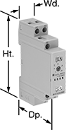
Dual-Channel DIN-Rail Mount Multifunction Timer Relays

Control two steps of an electrical process from a single relay—with two fully independent channels and 30 different functions, these relays give you a wide range of possibilities. Each channel has its own output, so you can run two different functions (one per circuit) at the same time. Mount them to 35 mm DIN rails (also known as DIN 3 rail) and connect them to lighting systems, conveyors, electric motors, and other systems. These relays are UL Listed, C-UL Listed, and CE Marked, meaning they meet U.S. and international safety standards.
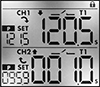
View times, function names, and on/off status for both channels at once using the digital display. You can program these relays with a joystick on the face, which is easier to use than the rotary dials on traditional relays. You can also program them using an Android phone with NFC (near field communication) capability, which is commonly used for mobile payment. Once you select the functions you need, hold the phone against the relay to program.
Connect switches to inputs on these relays to trigger, pause, and reset functions. Turning on a switch connected to the pause input stops functions until the switch is turned off. A switch connected to the reset input will start functions from the beginning. If the relay is actively receiving a signal, the function will restart right away. If there is no signal, the function will stop and reset, so it starts from the beginning the next time it’s triggered. You can use switches to pause or reset both channels at once, or for one channel only.
Use relays with proximity sensor compatibility to activate functions when your sensor is triggered, such as when an object approaches or a liquid level changes. These relays are compatible with both standard styles of sensors, PNP and NPN, and are often used for warning signals, motion-detecting light and heating systems, and automated assembly lines.
Although these relays have 30 different functions, they all fall into 10 categories. Within these categories, you can select different functions to allow you to add a switch, program a delay, or change how the relay responds to a trigger (turning on or off, pausing, or resetting).
Manual Switch Control—Use these functions to turn the relay on and off with a switch.
Fixed On/Off—The on function keeps the relay on whenever input voltage is applied; it will only turn off if the voltage is removed. The off function keeps the relay in an off state, even if input voltage is applied.
Switch-On (Single-Shot)—These functions require a switch to activate the relay, which stays on for the programmed amount of time. For example, lights in a storage room are turned on with a switch and stay on for a set time before turning off.
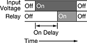
Delayed Start (Delay-on-Make)—These functions allow you to set how long it takes for the relay to turn on after input voltage is applied. For example, a drill starts pumping lubricant immediately, but it does not start rotating until the set time has elapsed.
Delayed Switch-Off (Delay-on-Break)—These functions use a switch instead of input voltage. When the switch is turned off, the relay remains on for a programmed amount of time before turning off. For example, a projector’s light is turned off with a switch, but its cooling fan continues to run for a set time.
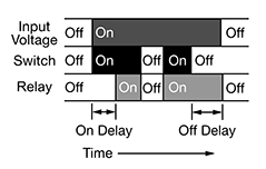
Delayed Switch-On with Delayed Switch-Off—This function uses a switch instead of an input voltage. It allows you to set how long it takes the relay to turn on after a switch is turned on, and how long it will stay on after the switch is turned off. For example, a furnace turns on, but the fan doesn’t start pushing air through the vents until it has been heated. When the furnace turns off, the fan keeps blowing to circulate all the hot air.
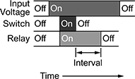
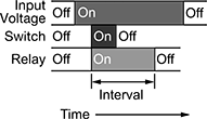
Interval—These functions use input voltage to turn on the relay for a programmed amount of time. For example, when a part moving down a conveyor reaches a certain location, a cleaning spray comes on for a set amount of time.
Repeat Cycle—When input voltage is applied, the relay turns on for a duration, then off for the same duration. They alternate between the two until input voltage is removed. For example, a flashing light stays on and off for equal periods of time.
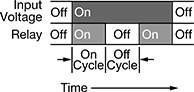
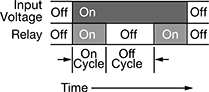
Asymmetrical Repeat Cycle—These functions start with an on-cycle and then have an off-cycle, but these cycles have different durations. The cycles repeat until input voltage is removed. For example, a sprinkler system sprays in short bursts followed by longer rest periods, on and off until input voltage is removed.
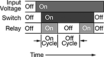
Switch-On Asymmetrical Repeat Cycle—These functions require a switch to activate the timing function. The input voltage is applied the whole time, and when you turn the switch on, the relay begins with an on-cycle followed by an off-cycle. These cycles have different durations, and they repeat until you turn the switch off. They could be used to turn on a motor or other system for a short period and then turn it off for a longer rest period, repeating that pattern until the switch is turned off.
![]() For technical drawings and 3-D models, click on a part number.
For technical drawings and 3-D models, click on a part number.
Timing Range | |||||||||||||
|---|---|---|---|---|---|---|---|---|---|---|---|---|---|
| No. of Terminals | Input Voltage | Control Current, mA | Timer Relay Function | No. of | Overall | Switching Current @ 240V AC | Max. Switching Voltage | Ht. | Wd. | Dp. | Features | Each | |
2 Circuit Controlled with 2 Off (Normally Open) and 2 On (Normally Closed)—DPDT | |||||||||||||
| 12 | 12V AC, 24V AC, 12V DC, 24V DC | 8 | Manual Switch Control Fixed On/Off Switch-On (Single-Shot) Delayed Start (Delay-on-Make) Delayed Switch-Off (Delay-on-Break) Delayed Switch-On with Delayed Switch-Off Interval Repeat Cycle Asymmetrical Repeat Cycle Switch-On Asymmetrical Repeat Cycle | 30 | 0.1 sec.-9,999 hrs. | 16A | 240V AC | 3.4" | 1.4" | 2.2" | 2 Individually Programmable Timers, LCD Screen, Proximity Sensor Compatability (PNP and NPN) | 0000000 | 0000000 |
| 12 | 120V AC, 240V AC, 110V DC, 240V DC | 16 | Manual Switch Control Fixed On/Off Switch-On (Single-Shot) Delayed Start (Delay-on-Make) Delayed Switch-Off (Delay-on-Break) Delayed Switch-On with Delayed Switch-Off Interval Repeat Cycle Asymmetrical Repeat Cycle Switch-On Asymmetrical Repeat Cycle | 30 | 0.1 sec.-9,999 hrs. | 16A | 240V AC | 3.4" | 1.4" | 2.2" | 2 Individually Programmable Timers, LCD Screen | 0000000 | 000000 |
DIN-Rail Mount Multifunction Timer Relays

Control multiple timing functions from your electrical cabinet—these timer relays mount to 35 mm DIN rail (also known as DIN 3 rail), which is the most commonly used size. UL Listed, C-UL Listed, and CE Marked, these relays meet American, Canadian, and European safety standards.
Timer Relays with Delayed, Interval, Switch-On, and Repeat Cycles
With six different functions, these timer relays have a broad range of applications. Use them to precisely control machines such as conveyors, lighting systems, and electric motors.
The delayed start (delay-on-make) function allows you to set how long it takes for the relay to turn on after input voltage is applied. For example, a drill starts pumping lubricant immediately, but it does not start rotating until the set time has elapsed.
The delayed switch-on with delayed switch-off function uses a switch instead of input voltage. It allows you to set how long it takes the relay to turn on after a switch is turned on, and how long it will stay on after the switch is turned off. For example, a furnace turns on, but the fan doesn’t start pushing air through the vents until it has been heated. When the furnace turns off, the fan keeps blowing to circulate all the hot air.
The delayed switch-off (delay-on-break) function uses a switch instead of input voltage. When the switch is turned off, the relay remains on for a programmed amount of time before turning off. For example, a projector’s light is turned off with a switch, but its cooling fan continues to run for a set time.
The interval function uses input voltage to turn on the relay for a programmed amount of time. For example, when a part moving down a conveyor reaches a certain location, a cleaning spray comes on for a set time.
The switch-on (single-shot) function requires a switch to activate the relay, which stays on for the programmed amount of time. For example, lights in a storage room are turned on with a switch and stay on for a set time before turning off.
The repeat cycle function alternates between an on cycle and off cycle of equal durations until input voltage is removed. A common example would be a flashing light.
Timer Relays with Asymmetrical Repeat Cycles
Use these timer relays when your repeat cycles have different on- and off-cycle durations.
The asymmetrical repeat cycle alternates between different durations of on and off for as long as input voltage is applied. For example, a sprinkler system sprays in short bursts followed by longer rest periods, on and off until input voltage is removed.
The switch-on asymmetrical repeat cycle function is activated with a switch instead of input voltage. It could be used to turn on an electric motor for a short period and then turn it off for a longer rest period, repeating that pattern until the switch is turned off.
Timing Range | ||||||||||||
|---|---|---|---|---|---|---|---|---|---|---|---|---|
| No. of Terminals | Input Voltage | Control Current, mA | Timer Relay Function | No. of | Overall | Switching Current @ 240V AC | Max. Switching Voltage | Ht. | Wd. | Dp. | Each | |
1 Circuit Controlled with 1 Off (Normally Open) or 1 On (Normally Closed)—SPDT | ||||||||||||
| 6 | 12V AC, 24V AC, 48V AC, 120V AC, 240V AC, 12V DC, 24V DC, 48V DC, 60V DC, 120V DC, 240V DC | 7 | Delayed Switch-On with Delayed Switch-Off Delayed Start (Delay-on-Make) Delayed Switch-Off (Delay-on-Break) Interval Switch-On (Single-Shot) Repeat Cycle | 6 | 0.1 sec.-24 hrs. | 16A | 240V AC | 3 1/2" | 0.7" | 2.4" | 000000 | 000000 |
| 6 | 12V AC, 24V AC, 48V AC, 120V AC, 240V AC, 12V DC, 24V DC, 48V DC, 60V DC, 120V DC, 240V DC | 7 | Asymmetrical Repeat Cycle Switch-On Asymmetrical Repeat Cycle | 6 | 0.1 sec.-24 hrs. | 16A | 240V AC | 3 1/2" | 0.7" | 2.4" | 0000000 | 00000 |