


About Timer Relays
More
Choosing an Electrical Switch
More
Toggle Switches

Switches with an on-on or on-(on) position designation alternate power between sets of terminals.
To view switch wiring diagrams, select a part number and click Product Detail.
![]() For technical drawings and 3-D models, click on a part number.
For technical drawings and 3-D models, click on a part number.
| No. of Circuits Controlled | Switch Starting Position | Switch Action | No. of Terminals | Industry Designation | Position Designation | Switching Current @ Voltage | Max. Voltage | For Max. Panel Thick. | Mounting Hardware Included | Choose a Wire Connection Type | Each | |
2 Position with Rounded Toggle | ||||||||||||
|---|---|---|---|---|---|---|---|---|---|---|---|---|
For 1/2" Panel Cutout Dia. | ||||||||||||
| 4 | 4 Off (Normally Open) or 4 On (Normally Closed) | Stays Switched (Maintained) | 12 | 4PDT | On-On | 15 A @ 125 V AC/28 V DC | 28V DC 250V AC | 0.13" | Yes | 00000000 | 000000 | |
| No. of Circuits Controlled | Switch Starting Position | Switch Action | No. of Terminals | Industry Designation | Position Designation | Switching Current @ Voltage | Max. Voltage | For Max. Panel Thick. | Mounting Hardware Included | Choose a Wire Connection Type | Each | |
3 Position with Rounded Toggle | ||||||||||||
|---|---|---|---|---|---|---|---|---|---|---|---|---|
For 1/2" Panel Cutout Dia. | ||||||||||||
| 4 | 4 Off (Normally Open) or 4 On (Normally Closed) | Stays Switched (Maintained) | 12 | 4PDT | On-Off-On | 15 A @ 125 V AC/28 V DC | 28V DC 250V AC | 0.13" | Yes | 00000000 | 000000 | |
Wet-Location Toggle Switches

A rubber seal protects these switches from splashing water.
NEMA 4, 13, and IP68 rated switches are protected against oil/coolant spraying, washdowns, and temporary submersion.
Switches with an on-on or on-(on) position designation alternate power between sets of terminals.
![]() For technical drawings and 3-D models, click on a part number.
For technical drawings and 3-D models, click on a part number.
| No. of Circuits Controlled | Switch Starting Position | Switch Action | No. of Terminals | Industry Designation | Position Designation | Switching Current @ Voltage | Max. Voltage | Mounting Hardware Included | Wire Connection Type | Each | |
2 Position with Rounded Toggle—NEMA 4, NEMA 13, IP68 | |||||||||||
|---|---|---|---|---|---|---|---|---|---|---|---|
For 1/2" Panel Cutout Dia. | |||||||||||
| 4 | 4 Off (Normally Open) or 4 On (Normally Closed) | Stays Switched (Maintained) | 12 | 4PDT | On-On | 15 A @ 125 V AC, 12 A @ 28 V DC | 28V DC 277V AC | Yes | Quick-Disconnect Terminals | 00000000 | 0000000 |
Mil. Spec. Washdown Toggle Switches

These switches meet MIL-S-3950. A rubber seal protects them from washdowns.
Switches with an on-on, on-on-on, or (on)-on-on position designation alternate power between sets of terminals.
![]() For technical drawings and 3-D models, click on a part number.
For technical drawings and 3-D models, click on a part number.
| No. of Circuits Controlled | Switch Starting Position | Switch Action | No. of Terminals | Industry Designation | Position Designation | Switching Current @ Voltage | Max. Voltage | Dp. Behind Panel | Mounting Hardware Included | Wire Connection Type | Each | |
2 Position | ||||||||||||
|---|---|---|---|---|---|---|---|---|---|---|---|---|
For 1/2" Panel Cutout Dia. | ||||||||||||
| 4 | 4 Off (Normally Open) or 4 On (Normally Closed) | Stays Switched (Maintained) | 12 | 4PDT | On-On | 15 A @ 125 V AC, 12 A @ 28 V DC | 28V DC 125V AC | 1.35" | Yes | Screw Terminals | 00000000 | 000000 |
3 Position | ||||||||||||
For 1/2" Panel Cutout Dia. | ||||||||||||
| 4 | 4 Off (Normally Open) or 4 On (Normally Closed) | Stays Switched (Maintained) | 12 | 4PDT | On-Off-On | 15 A @ 125 V AC, 12 A @ 28 V DC | 28V DC 125V AC | 1.35" | Yes | Screw Terminals | 00000000 | 000000 |
| 4 | 4 Off (Normally Open) or 4 On (Normally Closed) | Springs Back (Momentary) | 12 | 4PDT | (On)-Off-(On) | 8 A @ 125 V AC, 10 A @ 28 V AC | 28V DC 125V AC | 1.35" | Yes | Screw Terminals | 00000000 | 000000 |
Miniature Toggle Switches

Maximize the space in a panel—these switches are half the size of most toggle switches.
Switches with an on-on or on-(on) position designation alternate power between sets of terminals.
![]() For technical drawings and 3-D models, click on a part number.
For technical drawings and 3-D models, click on a part number.
| No. of Circuits Controlled | Switch Starting Position | Switch Action | No. of Terminals | Industry Designation | Position Designation | Switching Current @ Voltage | Max. Voltage | Dp. Behind Panel | Mounting Hardware Included | Wire Connection Type | Each | |
2 Position with Rounded Toggle | ||||||||||||
|---|---|---|---|---|---|---|---|---|---|---|---|---|
For 1/4" Panel Cutout Dia. | ||||||||||||
| 4 | 4 Off (Normally Open) or 4 On (Normally Closed) | Stays Switched (Maintained) | 12 | 4PDT | On-On | 6 A @ 125 V AC, 4 A @ 30 V DC | 30V DC 250V AC | 0.66" | Yes | Tab Terminals | 0000000 | 000000 |
High-Current Toggle Switches

Able to withstand high currents, these switches are often used with motors and pumps.
Switches with an on-on position designation alternate power between sets of terminals.
![]() For technical drawings and 3-D models, click on a part number.
For technical drawings and 3-D models, click on a part number.
| No. of Circuits Controlled | Switch Starting Position | Switch Action | No. of Terminals | Industry Designation | Position Designation | Switching Current @ Voltage | Max. Voltage | Dp. Behind Panel | Mounting Hardware Included | Each | |
2 Position with Quick-Disconnect Terminals | |||||||||||
|---|---|---|---|---|---|---|---|---|---|---|---|
For 1/2" Panel Cutout Dia. | |||||||||||
| 4 | 4 Off (Normally Open) or 4 On (Normally Closed) | Stays Switched (Maintained) | 12 | 4PDT | On-On | 20 A @ 125 V AC, 20 A @ 30 V DC | 30V DC 250V AC | 1.3" | Yes | 0000000 | 000000 |
2 Position with Tab Terminals | |||||||||||
For 1/2" Panel Cutout Dia. | |||||||||||
| 4 | 4 Off (Normally Open) or 4 On (Normally Closed) | Stays Switched (Maintained) | 12 | 4PDT | On-On | 20 A @ 125 V AC, 20 A @ 30 V DC | 30V DC 250V AC | 1.07" | Yes | 0000000 | 00000 |
3 Position with Quick-Disconnect Terminals | |||||||||||
For 1/2" Panel Cutout Dia. | |||||||||||
| 4 | 4 Off (Normally Open) or 4 On (Normally Closed) | Stays Switched (Maintained) | 12 | 4PDT | On-Off-On | 20 A @ 125 V AC, 20 A @ 30 V DC | 30V DC 250V AC | 1.3" | Yes | 0000000 | 00000 |
3 Position with Tab Terminals | |||||||||||
For 1/2" Panel Cutout Dia. | |||||||||||
| 4 | 4 Off (Normally Open) or 4 On (Normally Closed) | Stays Switched (Maintained) | 12 | 4PDT | On-Off-On | 20 A @ 125 V AC, 20 A @ 30 V DC | 30V DC 250V AC | 1.07" | Yes | 0000000 | 00000 |
DIN-Rail Mount Interface Relays

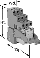
Isolate input and output circuits to prevent damage from voltage spikes, reduce signal interference, and amplify signal. These relays interface between your controller and components—they receive a signal from the controller to switch power on or off to the components. All have an LED indicator that shows you if your switch is actuated, so you know it’s connected and wired correctly. Use them to communicate signals to devices like motors or sensors. Mount them on 35 mm DIN rail (also known as DIN 3 rail).
Relays with spring-clamp terminals connect and disconnect to wires without needing to turn screws. Because there is no screw, these connections have less risk of loosening over time than screw terminals, even when there is vibration.
Relays with PLC output protection prevent voltage spikes created by the relay from damaging the output channel on your programmable logic controller (PLC).
![]() For technical drawings and 3-D models, click on a part number.
For technical drawings and 3-D models, click on a part number.
Relays with Relay Sockets | Replacement Relays | |||||||||||
|---|---|---|---|---|---|---|---|---|---|---|---|---|
| Number of Terminals | Input Voltage | Control Current, mA | Switching Current @ 240V AC | hp @ Switching Voltage | Ht. | Wd. | Dp. | Features | Each | Each | ||
4 Circuits Controlled with 4 Off (Normally Open) or 4 On (Normally Closed)—4PDT | ||||||||||||
With Screw Terminals | ||||||||||||
| 14 | 24V AC | 53 | 7A | 1/8 hp @ 120 V AC | 3.1" | 1.1" | 3.3" | LED Indicator, PLC Output Protection | 00000000 | 000000 | 00000000 | 000000 |
| 14 | 120V AC | 12 | 7A | 1/8 hp @ 120 V AC | 3.1" | 1.1" | 3.3" | LED Indicator, PLC Output Protection | 00000000 | 00000 | 00000000 | 00000 |
| 14 | 12V DC | 86 | 7A | 1/8 hp @ 120 V AC | 3.1" | 1.1" | 3.3" | LED Indicator, PLC Output Protection | 00000000 | 00000 | 00000000 | 00000 |
| 14 | 24V DC | 40 | 7A | 1/8 hp @ 120 V AC | 3.1" | 1.1" | 3.3" | LED Indicator, PLC Output Protection | 00000000 | 00000 | 00000000 | 00000 |
With Spring-Clamp Terminals | ||||||||||||
| 14 | 24V AC | 53 | 7A | 1/8 hp @ 120 V AC | 3.9" | 1.2" | 3.3" | LED Indicator, PLC Output Protection | 00000000 | 00000 | 00000000 | 00000 |
| 14 | 12V DC | 86 | 7A | 1/8 hp @ 120 V AC | 3.9" | 1.2" | 3.3" | LED Indicator, PLC Output Protection | 00000000 | 00000 | 00000000 | 00000 |
| 14 | 24V DC | 40 | 7A | 1/8 hp @ 120 V AC | 3.9" | 1.2" | 3.3" | LED Indicator, PLC Output Protection | 00000000 | 00000 | 00000000 | 00000 |
Open-Style Screw Terminal Relays

Optional covers protect contacts from dust and dirt.
Relays | Optional Covers | |||||||||||
|---|---|---|---|---|---|---|---|---|---|---|---|---|
| Number of Terminals | Input Voltage | Control Current, mA | Switching Current @ Voltage | Max. Switching Voltage | hp @ Switching Voltage | Ht. | Wd. | Dp. | Each | Each | ||
4 Circuits Controlled with 4 Off (Normally Open) or 4 On (Normally Closed)—4PDT | ||||||||||||
| 14 | 120V AC | 116 | 35 A @ 120 V AC 20 A @ 24 V DC | 120V AC | 1 hp @ 120 V AC 1 1/2 hp @ 240 V AC | 3.4" | 2.7" | 2.7" | 0000000 | 0000000 | 0000000 | 0000000 |
Compact Spade-Terminal Relays
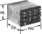

Fit these relays where standard spade-terminal relays are too big. You can connect them three ways. Plug them into a socket (sold separately), connect them with quick-disconnect terminals, or solder wires directly to the terminals. An LED indicator shows you the status of the relay, so you know it’s connected and wired correctly.
Relays that control 2 or more circuits have a lockable test button, so you can test their function. When you press the button, the relay switches contacts. Use this button when checking a relay for proper function before installing it, or when investigating issues with wired relays.
Relay sockets mount directly on 35 mm DIN rail (also known as DIN 3 rail) for fast installation. You can also mount them to a flat surface using screws.
![]() For technical drawings and 3-D models, click on a part number.
For technical drawings and 3-D models, click on a part number.
Relays | Relay Sockets with Screw Terminals | |||||||||||
|---|---|---|---|---|---|---|---|---|---|---|---|---|
| Number of Terminals | Input Voltage | Control Current, mA | Switching Current @ Voltage | Maximum Switching Voltage | Ht. | Wd. | Dp. | Quick-Disconnect Tab Wd. | Each | Each | ||
4 Circuits Controlled with 4 Off (Normally Open) or 4 On (Normally Closed)—4PDT | ||||||||||||
Relay-Socket Mount | ||||||||||||
| 14 | 24V AC | 50 | 8 A @ 120 V AC/24 V DC | 300V AC | 1.1" | 0.9" | 1.6" | 0.11" | 000000000 | 000000 | 0000000 | 000000 |
| 14 | 24V AC | 63 | 15 A @ 120 V AC 12 A @ 24 V DC | 300V AC | 1.1" | 1.6" | 1.6" | 0.187" | 00000000 | 00000 | 0000000 | 00000 |
| 14 | 120V AC | 10 | 8 A @ 120 V AC/24 V DC | 300V AC | 1.1" | 0.9" | 1.6" | 0.11" | 000000000 | 00000 | 0000000 | 00000 |
| 14 | 120V AC | 13 | 15 A @ 120 V AC 12 A @ 24 V DC | 300V AC | 1.1" | 1.6" | 1.6" | 0.187" | 00000000 | 00000 | 0000000 | 00000 |
| 14 | 240V AC | 5 | 8 A @ 120 V AC/24 V DC | 300V AC | 1.1" | 0.9" | 1.6" | 0.11" | 000000000 | 00000 | 0000000 | 00000 |
| 14 | 240V AC | 6 | 15 A @ 120 V AC 12 A @ 24 V DC | 300V AC | 1.1" | 1.6" | 1.6" | 0.187" | 00000000 | 00000 | 0000000 | 00000 |
| 14 | 12V DC | 92 | 8 A @ 120 V AC/24 V DC | 300V AC | 1.1" | 0.9" | 1.6" | 0.11" | 000000000 | 00000 | 0000000 | 00000 |
| 14 | 12V DC | 125 | 15 A @ 120 V AC 12 A @ 24 V DC | 300V AC | 1.1" | 1.6" | 1.6" | 0.187" | 00000000 | 00000 | 0000000 | 00000 |
| 14 | 24V DC | 6 | 15 A @ 120 V AC 12 A @ 24 V DC | 300V AC | 1.1" | 1.6" | 1.6" | 0.187" | 00000000 | 00000 | 0000000 | 00000 |
| 14 | 24V DC | 46 | 8 A @ 120 V AC/24 V DC | 300V AC | 1.1" | 0.9" | 1.6" | 0.11" | 000000000 | 00000 | 0000000 | 00000 |
Hazardous Location Relays
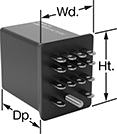
Sealed for safety, these relays are a good choice for hazardous locations where combustible or corrosive gases may be present.
Relays with circular-pin terminals or quick-disconnect terminals are hermetically sealed—completely air- and watertight—to shield internal parts from gases, moisture, and other contaminants. They plug into relay sockets (sold separately) for easy installation.
Relay sockets mount to 35 mm DIN rail (also known as DIN 3 rail) or flat surfaces.
![]() For technical drawings and 3-D models, click on a part number.
For technical drawings and 3-D models, click on a part number.
Relays | Relay Sockets | |||||||||||||
|---|---|---|---|---|---|---|---|---|---|---|---|---|---|---|
| Number of Terminals | Input Voltage | Control Current, mA | Switching Current @ Voltage | Max. Switching Voltage | hp @ Switching Voltage | Ht. | Wd. | Dp. | Quick-Disconnect Tab Wd. | Environmental Rating | Each | Each | ||
Quick-Disconnect Terminals—Hermetically Sealed | ||||||||||||||
4 Circuits Controlled with 4 Off (Normally Open) or 4 On (Normally Closed)—4PDT | ||||||||||||||
| 14 | 120V AC | 100 | 3 A @ 120 V AC/240 V AC | 240V AC | 1/10 hp @ 120 V AC | 1.2" | 0.9" | 1.3" | 0.125" | NEC Class I Division 2 Groups A, B, C, D | 0000000 | 0000000 | 0000000 | 000000 |
Solid State DIN-Rail Mount Multifunction Timer Relays
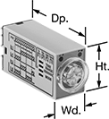
For fast installation, mount these relays to 35 mm DIN rail (also known as DIN 3 rail). They also mount to flat surfaces. With no moving parts, these solid state relays last longer and require less maintenance, are quieter, and switch faster than mechanical relays. They provide a variety of timing functions in one relay.
Use relays with DIP switches for more precise control than knobs. They make it easier to set multiple relays to the same timing range.
Relays that control 4 circuits require a relay socket (sold separately) to attach to DIN rail.
Timer Relays | ||||||||||||||
|---|---|---|---|---|---|---|---|---|---|---|---|---|---|---|
Timing Range | Relay Sockets | |||||||||||||
| No. of Terminals | Input Voltage | Control Current, mA | Timer Relay Function | No. of | O'all | Switching Current @ 240V AC | Max. Switching Voltage | Ht. | Wd. | Dp. | Each | Each | ||
Relays with Knob | ||||||||||||||
4 Circuit Control with 4 Off (Normally Open) or 4 On (Normally Closed)—4PDT | ||||||||||||||
| 14 | 120V AC | 15 | Delayed Start (Delay-on-Make) Interval Repeat Cycle | 4 | 0.1 sec.-10 min. | 3A | 250V AC | 1.1" | 0.9" | 2.1" | 000000 | 0000000 | 0000000 | 000000 |
| 14 | 240V AC | 9 | Delayed Start (Delay-on-Make) Interval Repeat Cycle | 4 | 0.1 sec.-10 min. | 3A | 250V AC | 1.1" | 0.9" | 2.1" | 000000 | 000000 | 0000000 | 00000 |
| 14 | 24V DC | 45 | Delayed Start (Delay-on-Make) Interval Repeat Cycle | 4 | 0.1 sec.-10 min. | 3A | 250V AC | 1.1" | 0.9" | 2.1" | 000000 | 000000 | 0000000 | 00000 |