


Choosing an Electrical Switch
More
Contact Blocks for Manual Switches

Make or break an electrical circuit. These contact blocks mount to manual switches and transmit an electrical signal when the switch actuator is engaged. You can stack multiple blocks, so a single switch can control several circuits. This is helpful in setups that require multiple systems to turn on or off at the same time. For example, the switch on a conveyor line could turn off the conveyor and turn on a diverter and alarm.
| No. of Circuits Controlled | Switch Starting Position | No. of Terminals | Industry Designation | Wire Connection Type | Environmental Rating | For Switch Manufacturer Series | Each | |
Sprecher & Schuh | ||||||||
|---|---|---|---|---|---|---|---|---|
| 3 | 1 Off (Normally Open) and 2 On (Normally Closed) | 6 | 3PST-1NO/2NC | Screw Terminals | IP20 | D7P | 0000000 | 000000 |
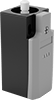
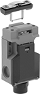
Build-Your-Own Limit Switches
Combine an actuator and a switch to assemble the exact limit switch you need. These switches have the rapid-closing action of a snap-acting switch, but have a larger actuator for large objects. When an object in motion comes into contact with the actuator, it sends a signal to open or close a circuit. They’re often used for conveyor systems and elevators. Each actuator style is compatible with all housing styles and vice versa.
Switches with a polypropylene plastic housing are lighter in weight than metal switches.
Switches with an LED power indicator and LED status indicator show you the status of the line and load phases. They give you extra assurance that your switch is connected and wired correctly.
IP65 switches protect against dust and splashing water. IP66 switches protect against dust and washdowns. IP67 switches protect against dust and temporary submersion.
![]() For technical drawings and 3-D models, click on a part number.
For technical drawings and 3-D models, click on a part number.
Terminals and
LED Indicator
Housing | Conduit | ||||||||||||||
|---|---|---|---|---|---|---|---|---|---|---|---|---|---|---|---|
| No. of Circuits Controlled | Switch Starting Position | Switch Action | Industry Designation | Switching Current @ Voltage | Max. Voltage | No. of Terminals | Lg. | Ht. | Dp. | No. of Connections | Thread Size | Environmental Rating | Specifications Met | Each | |
Polypropylene Plastic Housing | |||||||||||||||
Screw Terminals—LED Power Indicator and LED Status Indicator | |||||||||||||||
| 3 | 1 Off (Normally Open) and 2 On (Normally Closed) | Springs Back (Momentary) | 3PST-1NO/2NC | 3 A @ 24 V DC | 24V DC | 6 | 1.2" | 2.7" | 1.3" | 1 | M20 | IP65 | EN 50047 UL Listed C-UL Listed CE Marked CCC Marked | 0000000 | 0000000 |
| 3 | 1 Off (Normally Open) and 2 On (Normally Closed) | Springs Back (Momentary) | 3PST-1NO/2NC | 3 A @ 24 V DC | 24V DC | 6 | 1.6" | 3.1" | 1.5" | 1 | M20 | IP66, IP67 | EN 50041 UL Listed C-UL Listed CE Marked CCC Marked | 0000000 | 000000 |
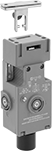
Hinge-Actuated Safety Switches
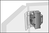
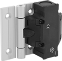
Replace the hinges on access doors or machine guards with these switches to keep your team safe from active machinery. Also known as interlock switches, they automatically shut off power to your machinery when the door or guard opens. They can be mounted on flat frames or aluminum T-slotted framing. These switches have positive-force, normally-closed contacts that will open a circuit when the switch is actuated, even if a spring fails or the contacts stick. They’re rated IP65 for protection from washdowns.
![]() For technical drawings and 3-D models, click on a part number.
For technical drawings and 3-D models, click on a part number.
Overall | ||||||||||||
|---|---|---|---|---|---|---|---|---|---|---|---|---|
| For Rail Ht., mm | Mounting Hole Ctr.-to-Ctr. Wd., mm | Switch Action | No. of Terminals | Industry Designation | Switching Current @ Voltage | Wire Connection Type | Conduit Thread Size | Ht. | Wd. | Dp. | Each | |
3 Circuits Controlled—1 Off (Normally Open) and 2 On (Normally Closed) | ||||||||||||
4° Actuation Angle—Aluminum Hinge | ||||||||||||
| 30 | 34 | Springs Back (Momentary) | 6 | 3PST-1NO/2NC | 2 A @ 230 V AC | Screw Terminals | M20 | 5.2" | 4.39" | 1.42" | 00000000 | 0000000 |
| 35 | 39 | Springs Back (Momentary) | 6 | 3PST-1NO/2NC | 2 A @ 230 V AC | Screw Terminals | M20 | 5.2" | 4.39" | 1.42" | 00000000 | 000000 |
| 40 | 44 | Springs Back (Momentary) | 6 | 3PST-1NO/2NC | 2 A @ 230 V AC | Screw Terminals | M20 | 3.62" | 4.39" | 1.42" | 0000000 | 000000 |
| 45 | 49 | Springs Back (Momentary) | 6 | 3PST-1NO/2NC | 2 A @ 230 V AC | Screw Terminals | M20 | 5.2" | 4.39" | 1.42" | 00000000 | 000000 |
4° Actuation Angle—Stainless Steel Hinge | ||||||||||||
| 40 | 44 | Springs Back (Momentary) | 6 | 3PST-1NO/2NC | 2 A @ 230 V AC | Screw Terminals | M20 | 3.62" | 4.39" | 1.42" | 00000000 | 000000 |
8° Actuation Angle—Aluminum Hinge | ||||||||||||
| 40 | 44 | Springs Back (Momentary) | 6 | 3PST-1NO/2NC | 2 A @ 230 V AC | Screw Terminals | M20 | 3.62" | 4.39" | 1.42" | 00000000 | 000000 |
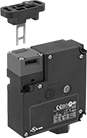
Frame-Mounted Safety Switches
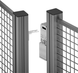
Also known as interlock switches, these ensure the safety of personnel by automatically shutting off power to machinery when an access door opens. Mount the switch to the door frame and mount a key to the door so that the key is inserted into the switch when the door is closed. When the door opens, the key is removed from the switch and the machine shuts down. They’re often used with machine guards for large robots.
All switches require an actuator key, but not all include one—check whether you need to pick out a separate actuator key. For some switch styles, you can also select the mounting orientation of the key. Flexible keys pivot at least 15°, making them easier to align with switches during installation.
Style A-G switches have positive-force, normally closed contacts that will open a circuit when the switch is actuated even if a spring fails or the contacts stick.
IP67 rated switches protect against temporary submersion.
![]() For technical drawings and 3-D models, click on a part number.
For technical drawings and 3-D models, click on a part number.

Housing | Conduit | ||||||||||||||||
|---|---|---|---|---|---|---|---|---|---|---|---|---|---|---|---|---|---|
| Style | No. of Circuits Controlled | Switch Starting Position | Switch Action | No. of Terminals | Industry Designation | Switching Current @ Voltage | Max. Voltage | Ht. | Wd. | Dp. | Trade Size | Thread Size | Thread Type | Key Included | Environmental Rating | Each | |
Screw Terminal Connection with Positive-Force Normally Closed Contacts | |||||||||||||||||
| C | 3 | 1 Off (Normally Open) and 2 On (Normally Closed) | Stays Switched (Maintained) | 3 | 3PST-1NO/2NC | 8 A @ 120 V AC, 4 A @ 24 V DC | 600V AC 250V DC | 3.5" | 2.1" | 1.2" | 1/2 | __ | NPT | Yes | IP67 | 00000000 | 0000000 |
| C | 3 | 1 Off (Normally Open) and 2 On (Normally Closed) | Stays Switched (Maintained) | 6 | 3PST-1NO/2NC | 4 A @ 230 V AC, 4 A @ 24 V DC | 500V AC 24V DC | 3.5" | 2" | 1.2" | __ | M16 | Metric | Yes | IP67 | 00000000 | 000000 |
| D | 3 | 1 Off (Normally Open) and 2 On (Normally Closed) | Stays Switched (Maintained) | 6 | 3PST-1NO/2NC | 6 A @ 120 V AC, 0.27 A @ 24 V DC | 240V AC 250V DC | 3.8" | 1.2" | 1.2" | 1/2 | __ | NPT | Yes | IP67 | 00000000 | 00000 |
Screw Terminal Connection with Positive-Force Normally Closed Contacts and Rotating Head | |||||||||||||||||
| C | 3 | 1 Off (Normally Open) and 2 On (Normally Closed) | Stays Switched (Maintained) | 6 | 3PST-1NO/2NC | 5 A @ 120 V AC, 5 A @ 24 V DC | 400V AC 400V DC | 3.5" | 2" | 1.3" | 1/2 | __ | NPT | Yes | IP65 | 00000000 | 000000 |
| D | 3 | 1 Off (Normally Open) and 2 On (Normally Closed) | Stays Switched (Maintained) | 6 | 3PST-1NO/2NC | 10 A @ 120 V AC, 2.5 A @ 125 V DC | 240V AC 250V DC | 3.8" | 1.2" | 1.2" | __ | M20 | Metric | No | IP67 | 00000000 | 00000 |
| G | 3 | 1 Off (Normally Open) and 2 On (Normally Closed) | Stays Switched (Maintained) | 6 | 3PST-1NO/2NC | 10 A @ 230 V AC, 4 A @ 24 V DC | 250V AC 24V DC | 4.3" | 1.6" | 1.4" | __ | M20 | Metric | No | IP67 | 00000000 | 000000 |


Access-Delay Frame-Mounted Safety Switches
Delay access to hazardous areas until conditions are safe; use these switches with machines that take time to stop after they are turned off. Mount the switch to the door frame and mount the key to the door so that the key is inserted into the switch when the door is closed. When the door is pulled, the key is held in place with 225 lbs. of force until the switch receives a signal from a time-delay relay, motion sensor, or position sensor (not included) that the machine’s motion has stopped. After the motion has stopped, the key can be removed from the switch, releasing the access door. They’re often used with machine guards. All have positive-force, normally-closed contacts that will open a circuit when the switch is actuated even if a spring fails or the contacts stick. They’re rated for protection from washdowns and temporary submersion.
Style A and B have a key entry on the top and side of the switch.
Emergency override keys (sold separately) bypass the access delay feature.
![]() For technical drawings and 3-D models, click on a part number.
For technical drawings and 3-D models, click on a part number.
Housing | ||||||||||||||||
|---|---|---|---|---|---|---|---|---|---|---|---|---|---|---|---|---|
| Style | No. of Circuits Controlled | Switch Starting Position | Switch Action | No. of Terminals | Industry Designation | Switching Current @ Voltage | Max. Voltage | Input Voltage | Holding Force, lbs. | Ht. | Wd. | Dp. | Wire Connection Type | Conduit Trade Size | Each | |
Positive-Force Normally Closed Contacts | ||||||||||||||||
| A | 3 | 1 Off (Normally Open) and 2 On (Normally Closed) | Stays Switched (Maintained) | 6 | 3PST-1NO/2NC | 5 A @ 120 V AC, 2 A @ 24 V DC | 500V AC 250V DC | 24V AC, 24V DC | 225 | 4.7" | 2.3" | 1.4" | Screw Terminals | 1/2 | 0000000 | 0000000 |
| A | 3 | 1 Off (Normally Open) and 2 On (Normally Closed) | Stays Switched (Maintained) | 6 | 3PST-1NO/2NC | 5 A @ 120 V AC, 2 A @ 24 V DC | 500V AC 250V DC | 110V AC | 225 | 4.7" | 2.3" | 1.4" | Screw Terminals | 1/2 | 0000000 | 000000 |
| B | 3 | 1 Off (Normally Open) and 2 On (Normally Closed) | Stays Switched (Maintained) | 14 | 3PST-1NO/2NC | 3 A @ 120 V AC, 2.5 A @ 24 V DC | 250V DC 240V AC | 24V DC | 225 | 3.7" | 3.5" | 1.4" | Screw Terminals | 1/2 | 0000000 | 000000 |
| Emergency Override Key for Style A | 0000000 | Each | 000000 |
Tamper-Resistant Magnetically Actuated Switches
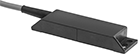
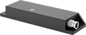
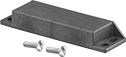
Prevent unauthorized use—these switches require coded magnets (sold separately) to actuate, and cannot be bypassed using ordinary magnets. They actuate when a magnet comes within sensing distance, and reset when the magnet moves away. Mount the switch in a stationary position, such as a door frame, and mount the magnet to a movable object, such as the door. They’re often used to detect when a door or window opens, and can be used with movable machine guards. All are rated IP67 for protection from temporary submersion.
Switches with an LED status indicator light up when they’re actuated, so you can see if they’re wired correctly with a quick glance.
Coded magnets include tamper-resistant one-way screws for mounting. To remove screws, see one-way bits and drivers.
Safety relays are required in safety applications with switches that control two or three circuits.
![]() For technical drawings and 3-D models, click on a part number.
For technical drawings and 3-D models, click on a part number.
Switches | Cables with Socket | Coded Magnets | |||||||||||||||
|---|---|---|---|---|---|---|---|---|---|---|---|---|---|---|---|---|---|
| No. of Circuits Controlled | Switch Starting Position | Industry Designation | Switching Current @ Voltage | Max. Voltage | Input Voltage | Max. Sensing Distance | Lg. | Wd. | Ht. | Environmental Rating | Each | Each | Each | ||||
Plastic Housing with Wire Leads | |||||||||||||||||
| B | 3 | 1 Off (Normally Open) and 2 On (Normally Closed) | 3PST-1NO/2NC | 10 mA @ 24 V DC | 24V DC | 24V DC | 0.2" | 3.5" | 1" | 0.5" | IP67 | 0000000 | 0000000 | 000000 | 00 | 0000000 | 000000 |
| B | 3 | 1 Off (Normally Open) and 2 On (Normally Closed) | 3PST-1NO/2NC | 0.4 A @ 100 V AC/100 V DC | 100V AC 100V DC | 100V AC 100V DC | 0.2" | 3.5" | 1" | 0.5" | IP67 | 0000000 | 000000 | 000000 | 00 | 0000000 | 00000 |
Plastic Housing with 4-Pole Nano M8 Plug and LED Status Indicator | |||||||||||||||||
| B | 3 | 1 Off (Normally Open) and 2 On (Normally Closed) | 3PST-1NO/2NC | 10 mA @ 24 V DC | 24V DC | 24V DC | 0.2" | 3.5" | 1" | 0.5" | IP67 | 0000000 | 000000 | 0000000 | 000000 | 0000000 | 00000 |