


Matching Flow Diagrams to Replace an Air Directional Control Valve
More
Choosing an Air Directional Control Valve
More
Choosing an Electrical Switch
More
Snap-Acting Switches

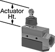
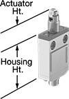
Open and close circuits in a snap. These switches actuate quickly to minimize arcing and prevent contacts from sticking. They’re often used to indicate that an appliance or enclosure door is open. You can also use them inside limit, pressure, and temperature switches.
Switches with a roller plunger or cross roller plunger actuator have a roller that moves when an object pushes the actuator. This reduces friction to limit wear and tear on your switch.
Plastic covers (sold separately) are compatible with switches with screw terminals. They fit over the bottom of the switch to prevent contact with live terminals.
![]() For technical drawings and 3-D models, click on a part number.
For technical drawings and 3-D models, click on a part number.
Switches | |||||||||||||||||
|---|---|---|---|---|---|---|---|---|---|---|---|---|---|---|---|---|---|
Housing | Plastic Covers | ||||||||||||||||
| No. of Circuits Controlled | Switch Starting Position | Switch Action | Industry Designation | Switching Current @ Voltage | Max. Voltage | Horsepower @ Switching Voltage | Operating Temp. Range, °F | Actuator Ht. | No. of Terminals | Lg. | Ht. | Dp. | Each | Each | |||
Roller Plunger Actuator Style for 1/2" Panel Cutout Dia. | |||||||||||||||||
With Screw Terminals | |||||||||||||||||
| D | 1 | 1 Off (Normally Open) or 1 On (Normally Closed) | Springs Back (Momentary) | SPDT | 15 A @ 250 V AC, 0.5 A @ 125 V DC | 480V AC 250V DC | 1/4 hp @ 250 V AC | -67° to 185° | 1.4" | 3 | 1.94" | 0.95" | 0.69" | 0000000 | 000000 | 0000000 | 00000 |
| D | 1 | 1 Off (Normally Open) or 1 On (Normally Closed) | Springs Back (Momentary) | SPDT | 20 A @ 250 V AC, 0.5 A @ 125 V DC | 480V AC 250V DC | 2 hp @ 250 V AC | -67° to 185° | 1.4" | 3 | 1.94" | 0.95" | 0.69" | 0000000 | 00000 | 0000000 | 0000 |
With Tab Terminals | |||||||||||||||||
| D | 1 | 1 Off (Normally Open) or 1 On (Normally Closed) | Springs Back (Momentary) | SPDT | 15 A @ 250 V AC, 15 A @ 8 V DC | 500V AC 250V DC | __ | -13° to 176° | 1.3" | 3 | 1.94" | 0.95" | 0.69" | 0000000 | 00000 | 000000 | 00 |
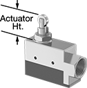
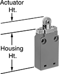
Enclosed Washdown Snap-Acting Switches
Rated NEMA 4 and IP66, these enclosed switches have a sealed actuator for protection from washdowns. They open and close circuits quickly to minimize arcing and prevent contacts from sticking.
![]() For technical drawings and 3-D models, click on a part number.
For technical drawings and 3-D models, click on a part number.
Housing | |||||||||||||||||
|---|---|---|---|---|---|---|---|---|---|---|---|---|---|---|---|---|---|
| No. of Circuits Controlled | Switch Starting Position | Switch Action | Industry Designation | Switching Current @ Voltage | Max. Voltage | Horsepower @ Switching Voltage | Operating Temp. Range, °F | Actuator Ht. | Wire Connection Type | No. of Terminals | Lg. | Ht. | Dp. | Conduit Trade Size | Each | ||
Side Mount | |||||||||||||||||
Roller Plunger Actuator Style | |||||||||||||||||
| B | 1 | 1 Off (Normally Open) or 1 On (Normally Closed) | Springs Back (Momentary) | SPDT | 15 A @ 250 V AC, 0.5 A @ 125 V DC | 600V AC 250V DC | 1/4 hp @ 250 V AC | -25° to 160° | 1.6" | Screw Terminals | 3 | 1" | 1.75" | 3.04" | 1/2 | 0000000 | 0000000 |
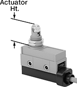
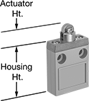
Enclosed Snap-Acting Switches
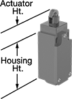
Enclosures protect these snap-acting switches from the environment. They open and close circuits quickly to minimize arcing and prevent contacts from sticking. They’re often used as door-open indicators on appliances and enclosures or as an internal component in limit, pressure, and temperature switches.
Switches with a roller plunger, cross roller plunger, or roller lever actuator allow parts to glide across the actuation surface with less friction than standard plungers or levers. This prevents wear and tear over time.
![]() For technical drawings and 3-D models, click on a part number.
For technical drawings and 3-D models, click on a part number.
Housing | |||||||||||||||||
|---|---|---|---|---|---|---|---|---|---|---|---|---|---|---|---|---|---|
| No. of Circuits Controlled | Switch Starting Position | Switch Action | Industry Designation | Switching Current @ Voltage | Max. Voltage | Horsepower @ Switching Voltage | Operating Temp. Range, °F | Actuator Ht. | Wire Connection Type | No. of Terminals | Lg. | Ht. | Dp. | Conduit Trade Size | Each | ||
Side Mount | |||||||||||||||||
Roller Plunger Actuator Style | |||||||||||||||||
| B | 1 | 1 Off (Normally Open) or 1 On (Normally Closed) | Springs Back (Momentary) | SPDT | 15 A @ 250 V AC, 0.5 A @ 125 V DC | 600V AC 250V DC | 1/4 hp @ 250 V AC | -25° to 160° | 1.2" | Screw Terminals | 3 | 3.04" | 1.75" | 1" | 1/2 | 0000000 | 0000000 |
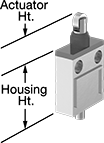
Enclosed Wet-Location Snap-Acting Switches
Rated IP67, these switches have an enclosure that shields their interior during temporary submersion. They open and close circuits in a snap—their quick actuation limits arcing and keeps contacts from sticking. These switches are often used to indicate an open appliance or enclosure door. You can also use them inside limit, pressure, and temperature switches.
Switches with a roller plunger actuator have a roller that moves parallel to the body length when an object pushes the actuator. This reduces friction to limit wear and tear on your switch.
Switches with a 4-pole micro M12 plug quickly connect and disconnect from your switch. Use cables (sold separately) to wire your switch connection to your setup.
![]() For technical drawings and 3-D models, click on a part number.
For technical drawings and 3-D models, click on a part number.
Micro
M12 Plug
Housing | ||||||||||||||
|---|---|---|---|---|---|---|---|---|---|---|---|---|---|---|
| No. of Circuits Controlled | Switch Starting Position | Switch Action | Industry Designation | Switching Current @ Voltage | Max. Voltage | Operating Temp. Range, °F | Actuator Ht. | No. of Wire Leads | Lg. | Ht. | Dp. | Specifications Met | Each | |
Roller Plunger Actuator Style for 9/16" Panel Cutout Dia. | ||||||||||||||
With 39" Wire Leads | ||||||||||||||
| 1 | 1 Off (Normally Open) or 1 On (Normally Closed) | Springs Back (Momentary) | SPDT | 10 A @ 250 V AC, 0.5 A @ 125 V DC | 250V AC 250V DC | 15° to 175° | 1.04" | 3 | 2.76" | 1.61" | 0.85" | UL Recognized Component, CE Marked | 0000000 | 0000000 |
With 108" Wire Leads | ||||||||||||||
| 1 | 1 Off (Normally Open) or 1 On (Normally Closed) | Springs Back (Momentary) | SPDT | 10 A @ 250 V AC, 0.5 A @ 125 V DC | 250V AC 250V DC | 15° to 175° | 1.04" | 3 | 2.76" | 1.61" | 0.85" | UL Recognized Component, CE Marked | 0000000 | 000000 |
With 4-Pole Micro M12 Plug | ||||||||||||||
| 1 | 1 Off (Normally Open) or 1 On (Normally Closed) | Springs Back (Momentary) | SPDT | 0.1 A @ 30 V DC | 30V DC | 45° to 155° | 1.06" | __ | 2.24" | 1.3" | 0.71" | EN 60947-5-1 | 0000000 | 000000 |
| 1 | 1 Off (Normally Open) or 1 On (Normally Closed) | Springs Back (Momentary) | SPDT | 1 A @ 30 V DC | 30V DC | 45° to 155° | 1.06" | __ | 2.24" | 1.3" | 0.71" | EN 60947-5-1 | 0000000 | 000000 |
Limit Switches
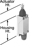
When a moving object contacts the actuator on these switches, they open or close a circuit. They have the rapid-closing action of a snap-acting switch, but with a larger actuator. This makes them a good choice for use with large objects—for instance, a box on a conveyor runs into the switch, stopping the conveyor.
Switches with a roller plunger or cross roller plunger actuator have a roller that moves when an object pushes the actuator. This reduces friction during actuation to limit wear and tear on your switch. Switches with a 4-pole micro M12 plug connect to cables with a socket (sold separately), allowing you to quickly connect and disconnect the switch.
Switches rated NEMA 13 are protected against dirt and oil/coolant spraying. Switches rated IP67 are protected against dust and temporary submersion.
![]() For technical drawings and 3-D models, click on a part number.
For technical drawings and 3-D models, click on a part number.
Switches | ||||||||||||||||||
|---|---|---|---|---|---|---|---|---|---|---|---|---|---|---|---|---|---|---|
Housing | Conduit | Cables with Socket | ||||||||||||||||
| Style | No. of Circuits Controlled | Switch Starting Position | Switch Action | Industry Designation | Switching Current @ Voltage | Max. Voltage | Operating Temp. Range, °F | Actuator Ht. | Lg. | Ht. | Dp. | Housing Material | Trade Size | Environmental Rating | Each | Each | ||
Roller Plunger Actuator Style | ||||||||||||||||||
With Screw Terminals | ||||||||||||||||||
| B | 1 | 1 Off (Normally Open) or 1 On (Normally Closed) | Springs Back (Momentary) | SPDT | 0.5 A @ 380 V AC, 220 V DC | 380V AC 220V DC | -4° to 158° | 1.3" | 1.1" | 2.5" | 1" | Zinc | __ | NEMA 13, IP67 | 000000 | 000000 | 000000 | 00 |
| B | 1 | 1 Off (Normally Open) or 1 On (Normally Closed) | Springs Back (Momentary) | SPDT | 10 A @ 300 V AC, 24 V DC | 300V AC 250V DC | 14° to 176° | 1.6" | 1.6" | 2.7" | 1.6" | Aluminum | 1/2 | IP67 | 0000000 | 00000 | 000000 | 00 |
With 4-Pole Micro M12 Plug | ||||||||||||||||||
| B | 1 | 1 Off (Normally Open) or 1 On (Normally Closed) | Springs Back (Momentary) | SPDT | 3 A @ 250 V AC, 250 V DC | 250V AC 250V DC | -22° to 158° | 1.2" | 1.1" | 2.5" | 1.2" | Plastic | __ | IP67 | 00000000 | 00000 | 0000000 | 000000 |
Build-Your-Own Limit Switches
Combine an actuator and a switch to assemble the exact limit switch you need. These switches have the rapid-closing action of a snap-acting switch, but have a larger actuator for large objects. When an object in motion comes into contact with the actuator, it sends a signal to open or close a circuit. They’re often used for conveyor systems and elevators. Each actuator style is compatible with all housing styles and vice versa.
Roller-plunger actuators open or close circuits when an object pushes against the roller, which moves the plunger. The roller helps push the plunger even if the force isn’t straight on. The roller also reduces friction during actuation which prevents wear and tear over time.
![]() For technical drawings and 3-D models, click on a part number.
For technical drawings and 3-D models, click on a part number.

Wireless Self-Powered Limit Switches
Install these limit switches where changing a battery or routing wires might be difficult—they power themselves when a moving object contacts the actuator. Place them up to 330 ft. away from the receiver (sold separately). These switches have the rapid-closing action of a snap-acting switch, but with a larger actuator.
Roller-plunger actuators open or close circuits when an object pushes against the roller, which moves the plunger. The roller moves parallel to the mounting direction, so it helps push the plunger even if the force isn’t straight on. The roller also reduces friction during actuation which prevents wear and tear over time.
Use an antenna (sold separately) to increase the maximum transmission range to 984 ft. They also strengthen the signal if there are obstacles between your switch and receiver.
![]() For technical drawings and 3-D models, click on a part number.
For technical drawings and 3-D models, click on a part number.

Housing | ||||||||||||||
|---|---|---|---|---|---|---|---|---|---|---|---|---|---|---|
| No. of Circuits Controlled | Max. Transmission Distance, ft. | Transmission Frequency | Switch Action | Actuator Material | Operating Temp. Range, °F | Actuator Height | Lg. | Ht. | Dp. | Housing Material | Specifications Met | Each | ||
Roller Plunger Actuator Style | ||||||||||||||
| B | 1 | 330 | 2,405 MHz | Springs Back (Momentary) | Steel | -13° to 131° | 0.8" | 1.2" | 2 1/2" | 0.6" | Plastic | CE Marked, IEC 60947-5, EN 60947-5 | 0000000 | 0000000 |

| No. of Outputs | Max. Transmission Distance, ft. | Transmission Frequency | Max. Switching Current @ Voltage | Input Voltage | Signal Output Type | Mounting Location | For DIN Rail Size | Wd. | Ht. | Dp. | Environmental Rating | Specifications Met | Each | |
With Screw Terminals | ||||||||||||||
|---|---|---|---|---|---|---|---|---|---|---|---|---|---|---|
| 2 | 330 | 2,405 MHz | 200 mA @ 24 V DC | 24V DC | PNP | DIN Rail | 35 mm | 1 7/16" | 4 1/4" | 2 15/16" | IP20 | CE Marked, IEC 60947-1, IEC 60947-5-1, EN 60947-5-1, EN 60947-1 | 0000000 | 0000000 |
| Max. Transmission Distance, ft. | Transmission Frequency | Input Voltage | Cable Lg., ft. | Environmental Rating | Specifications Met | Each | |
With Wire Leads | |||||||
|---|---|---|---|---|---|---|---|
| 984 | 2,405 MHz | 24V AC-240V AC, 24V DC-240V DC | 16 | IP65 | UL Listed, CSA Certified, CE Marked | 0000000 | 0000000 |
Low-Profile Limit Switches
Stack these slim switches together, or fit them into tight spaces. They're rated IP67 for protection from temporary submersion. When an object in motion comes into contact with the actuator, it sends a signal to open or close a circuit. These switches have the rapid-closing action of a snap-acting switch, but have a larger actuator for large objects. They’re often used on conveyor systems and elevators.
Roller-plunger actuators open or close circuits when an object pushes against the roller, which moves the plunger. The roller moves parallel to the mounting direction, so it helps push the plunger even if the force isn’t straight on. The roller also reduces friction during actuation which prevents wear and tear over time.
Switches with a 4-pole micro M12 plug connect to cables with a socket (sold separately), allowing you to quickly connect and disconnect the switch.
Switches with plastic or powder-coated zinc housings are rated NEMA 4 and 13 for protection from washdowns and oil/coolant spraying.
![]() For technical drawings and 3-D models, click on a part number.
For technical drawings and 3-D models, click on a part number.
Housing | ||||||||||||||||
|---|---|---|---|---|---|---|---|---|---|---|---|---|---|---|---|---|
| No. of Circuits Controlled | Switch Starting Position | Switch Action | Industry Designation | Switching Current @ Voltage | Max. Voltage | Operating Temp. Range, °F | Actuator Ht. | No. of Wire Leads | Cable Lead Lg., ft. | Lg. | Ht. | Dp. | Housing Material | Each | ||
Roller Plunger Actuator Style | ||||||||||||||||
With Wire Leads | ||||||||||||||||
| B | 1 | 1 Off (Normally Open) or 1 On (Normally Closed) | Springs Back (Momentary) | SPDT | 5 A @ 250 V AC, 4 A @ 30 V DC | 250V DC 250V AC | 14° to 158° | 0.6" | 4 | 9.5 | 1.6" | 2" | 0.6" | Aluminum | 0000000 | 0000000 |
| D | 1 | 1 Off (Normally Open) or 1 On (Normally Closed) | Springs Back (Momentary) | SPDT | 3 A @ 240 V AC, 0.55 A @ 125 V DC | 250V DC 240V AC | -13° to 158° | 0.6" | 4 | 3 | 1.2" | 2.2" | 0.7" | Plastic | 0000000 | 00000 |
| D | 1 | 1 Off (Normally Open) or 1 On (Normally Closed) | Springs Back (Momentary) | SPDT | 3 A @ 240 V AC, 0.55 A @ 125 V DC | 250V DC 240V AC | -13° to 158° | 0.6" | 4 | 3 | 1.2" | 2.2" | 0.7" | Powder-Coated Zinc | 0000000 | 00000 |
| D | 2 | 2 Off (Normally Open) and 2 On (Normally Closed) | Springs Back (Momentary) | DPDT | 3 A @ 240 V AC, 0.55 A @ 125 V DC | 250V DC 240V AC | -13° to 158° | 0.6" | 8 | 3 | 1.2" | 2.2" | 0.7" | Plastic | 0000000 | 00000 |
| D | 2 | 2 Off (Normally Open) and 2 On (Normally Closed) | Springs Back (Momentary) | DPDT | 3 A @ 240 V AC, 0.55 A @ 125 V DC | 250V DC 240V AC | -13° to 158° | 0.6" | 8 | 3 | 1.2" | 2.2" | 0.7" | Powder-Coated Zinc | 0000000 | 00000 |
With 4-Pole Micro M12 Plug | ||||||||||||||||
| B | 1 | 1 Off (Normally Open) or 1 On (Normally Closed) | Springs Back (Momentary) | SPDT | 1 A @ 125 V AC | 125V AC | 14° to 158° | 0.6" | __ | __ | 1.6" | 2.3" | 0.6" | Aluminum | 0000000 | 000000 |
| Cable with Socket for Switches with 4-Pole Micro M12 Plugs | 0000000 | Each | 000000 |
Sealed Low-Profile Limit Switches
A sealed actuator prevents these switches from jamming, even when exposed to sand, mud, or dirt. They're also rated IP67 for temporary submersion. With a slim design, you can stack them or fit them in tight spaces. When an object in motion comes into contact with the actuator, it sends a signal to open or close a circuit. These switches have the rapid-closing action of a snap-acting switch, but with a larger actuator. This makes them a good choice for use with large objects. For instance, a box on a conveyor runs into the switch, stopping the conveyor.
Switches with a roller plunger or cross roller plunger actuator have a roller that moves when an object pushes the actuator. This reduces friction during actuation to limit wear and tear on your switch.
Switches with a 4-pole micro M12 plug connect to cables with a socket (sold separately), allowing you to quickly connect and disconnect the switch.
![]() For technical drawings and 3-D models, click on a part number.
For technical drawings and 3-D models, click on a part number.
Housing | ||||||||||||||||
|---|---|---|---|---|---|---|---|---|---|---|---|---|---|---|---|---|
| No. of Circuits Controlled | Switch Starting Position | Switch Action | Industry Designation | Switching Current @ Voltage | Max. Voltage | Operating Temp. Range, °F | Actuator Ht. | No. of Wire Leads | Cable Lead Lg., ft. | Lg. | Ht. | Dp. | Housing Material | Each | ||
Roller Plunger Actuator Style | ||||||||||||||||
With Wire Leads | ||||||||||||||||
| C | 1 | 1 Off (Normally Open) or 1 On (Normally Closed) | Springs Back (Momentary) | SPDT | 5 A @ 250 V AC, 4 A @ 30 V DC | 250V DC 250V AC | 14° to 158° | 1" | 4 | 9.5 | 1.3" | 1.9" | 0.6" | Aluminum | 0000000 | 0000000 |
With 4-Pole Micro M12 Plug | ||||||||||||||||
| C | 1 | 1 Off (Normally Open) or 1 On (Normally Closed) | Springs Back (Momentary) | SPDT | 1 A @ 30 V DC | 30V DC | 14° to 158° | 1" | __ | __ | 1.6" | 2.2" | 0.6" | Aluminum | 00000000 | 000000 |
| C | 1 | 1 Off (Normally Open) or 1 On (Normally Closed) | Springs Back (Momentary) | SPDT | 1 A @ 125 V AC | 125V AC | 14° to 158° | 1" | __ | __ | 1.6" | 2.2" | 0.6" | Aluminum | 00000000 | 000000 |
| Cable with Socket for Switches with 4-Pole Micro M12 Plugs | 0000000 | Each | 000000 |
Panel-Mount Low-Profile Limit Switches
Secure these switches into panel cutouts using mounting nuts. They have a slim body so they can also be stacked together or fit into tight spaces. These switches have the rapid-closing action of a snap-acting switch, but have a larger actuator for large objects. When an object in motion comes into contact with the actuator, it sends a signal to open or close a circuit. They’re often used on conveyor systems and elevators. All are rated IP67 for protection from temporary submersion. They have a 4-pole micro M12 plug that connects to cables with a socket (sold separately), allowing you to quickly connect and disconnect the switch.
Roller-plunger actuators open or close circuits when an object pushes against the roller, which moves the plunger. The roller moves parallel to the mounting direction, so it helps push the plunger even if the force isn’t straight on. The roller also reduces friction during actuation which prevents wear and tear over time.
![]() For technical drawings and 3-D models, click on a part number.
For technical drawings and 3-D models, click on a part number.
Housing | ||||||||||||||
|---|---|---|---|---|---|---|---|---|---|---|---|---|---|---|
| No. of Circuits Controlled | Switch Starting Position | Switch Action | Industry Designation | Switching Current @ Voltage | Max. Voltage | Operating Temp. Range, °F | Actuator Ht. | Lg. | Ht. | Dp. | Housing Material | For Panel Cutout Dia. | Each | |
Roller Plunger Actuator Style | ||||||||||||||
With 4-Pole Micro M12 Plug | ||||||||||||||
| 1 | 1 Off (Normally Open) or 1 On (Normally Closed) | Springs Back (Momentary) | SPDT | 1 A @ 125 V AC | 125V AC | 14° to 158° | 1" | 1.6" | 2.2" | 0.6" | Aluminum | 0.57" | 0000000 | 0000000 |
| Cable with Socket | 0000000 | Each | 000000 |
Compact Safety Limit Switches
Shorter and thinner than other safety limit switches, these are sized to fit tight spaces. They protect machinery and ensure the safety of personnel. Positive-force contacts open the circuit when actuated, even if a spring fails or the contacts stick. They send a signal to your circuit when an object hits the actuator—for instance, a box on a conveyor runs into the switch, stopping the conveyor. They open and close circuits as fast as snap-acting switches, but they have a bigger actuator for large objects. All are NEMA and IP rated for protection from washdowns.
Switches with a roller plunger actuator have a roller that moves parallel to the mounting direction when an object pushes the actuator. This reduces friction during actuation to limit wear and tear.
NEMA 13 and IP67 rated switches are protected from oil/coolant spraying and temporary submersion.
![]() For technical drawings and 3-D models, click on a part number.
For technical drawings and 3-D models, click on a part number.
Housing | ||||||||||||||||
|---|---|---|---|---|---|---|---|---|---|---|---|---|---|---|---|---|
| Style | No. of Circuits Controlled | Switch Starting Position | Switch Action | Industry Designation | Switching Current @ Voltage | Max. Voltage | Operating Temp. Range, °F | Actuator Ht. | Wire Connection Type | Lg. | Ht. | Dp. | Housing Material | Environmental Rating | Each | |
Roller Plunger Actuator Style | ||||||||||||||||
| B | 1 | 1 Off (Normally Open) or 1 On (Normally Closed) | Springs Back (Momentary) | SPDT | 3 A @ 240 V AC, 0.27 A @ 250 V DC | 250V DC 240V AC | -40° to 185° | 1.1" | Screw Terminals | 1.2" | 2.6" | 1.2" | Plastic | NEMA 4X, NEMA 13, IP66, IP67 | 00000000 | 000000 |
| B | 1 | 1 Off (Normally Open) or 1 On (Normally Closed) | Springs Back (Momentary) | SPDT | 10 A @ 240 V AC, 4 A @ 24 V DC | 240V AC 24V DC | -22° to 176° | 1.2" | Screw Terminals | 1.2" | 2.4" | 1.2" | Plastic | NEMA 4, IP65 | 00000000 | 000000 |
| B | 1 | 1 Off (Normally Open) or 1 On (Normally Closed) | Springs Back (Momentary) | SPDT | 10 A @ 300 V AC, 10 A @ 250 V DC | 300V AC 250V DC | -40° to 185° | 1.1" | Screw Terminals | 1.2" | 2.4" | 1.2" | Zinc | NEMA 4, NEMA 13, IP66, IP67 | 0000000 | 000000 |
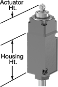
Safety Limit Switches

Protect machinery and ensure the safety of personnel—these switches have positive-force contacts that will open the circuit when actuated even if a spring fails or the contacts stick. When an object in motion comes into contact with the actuator, it sends a signal to open or close a circuit. These switches have the rapid-closing action of a snap-acting switch, but with a larger actuator. This makes them a good choice for use with large objects—for instance, a box on a conveyor runs into the switch, stopping the conveyor.
Switches with a roller plunger actuator have a roller that moves parallel to the mounting direction when an object pushes the actuator. This reduces friction during actuation to limit wear and tear on your switch.
Switches with a steel actuator are more durable than switches with a plastic actuator. They also handle higher loads.
![]() For technical drawings and 3-D models, click on a part number.
For technical drawings and 3-D models, click on a part number.
Housing | |||||||||||||||||
|---|---|---|---|---|---|---|---|---|---|---|---|---|---|---|---|---|---|
| Style | No. of Circuits Controlled | Switch Starting Position | Switch Action | Industry Designation | Actuator Material | Switching Current @ Voltage | Max. Voltage | Operating Temp. Range, °F | Actuator Ht. | Wire Connection Type | Lg. | Ht. | Dp. | Housing Material | Environmental Rating | Each | |
Roller Plunger Actuator Style | |||||||||||||||||
| B | 1 | 1 Off (Normally Open) or 1 On (Normally Closed) | Springs Back (Momentary) | SPDT | Steel | 10 A @ 600 V AC, 10 A @ 250 V DC | 600V AC 250V DC | -13° to 185° | 1.8" | Screw Terminals | 1.7" | 3.2" | 1.7" | Zinc | NEMA 4, NEMA 13, IP67 | 0000000 | 0000000 |
Washdown Limit Switches
Rated NEMA 3S and IP69K, these switches can handle washdowns with high pressures and temperatures. They’re also protected from oil/coolant spraying, precipitation, and temporary submersion. When an object in motion contacts the actuator, it sends a signal to open or close a circuit. These switches have the rapid-closing action of a snap-acting switch, but with a larger actuator. This makes them a good choice for use with large objects—for instance, a box on a conveyor runs into the switch, stopping the conveyor.
Switches with a roller plunger actuator trigger just like a plunger actuator but reduce friction during actuation thanks to their roller. This limits wear and tear on the switch.
![]() For technical drawings and 3-D models, click on a part number.
For technical drawings and 3-D models, click on a part number.
Housing | ||||||||||||||||
|---|---|---|---|---|---|---|---|---|---|---|---|---|---|---|---|---|
| Style | No. of Circuits Controlled | Switch Starting Position | Switch Action | Industry Designation | Switching Current @ Voltage | Max. Voltage | Operating Temp. Range, °F | Actuator Ht. | No. of Wire Leads | Cable Lead Lg., ft. | Lg. | Ht. | Dp. | Housing Material | Each | |
Roller Plunger Actuator Style | ||||||||||||||||
With Wire Leads | ||||||||||||||||
| B | 1 | 1 Off (Normally Open) or 1 On (Normally Closed) | Springs Back (Momentary) | SPDT | 10 A @ 240 V AC, 1 A @ 125 V DC | 600V AC 250V DC | 14° to 221° | 1.9" | 5 | 8 | 1.5" | 3.1" | 1.6" | Zinc | 0000000 | 0000000 |
| B | 2 | 2 Off (Normally Open) or 2 On (Normally Closed) | Springs Back (Momentary) | DPDT | 10 A @ 240 V AC, 1 A @ 250 V DC | 240V AC 250V DC | 14° to 221° | 1.9" | 5 | 8 | 1.5" | 3.1" | 1.6" | Zinc | 00000000 | 000000 |
Single-Action Mechanically Operated Air Directional Control Valves

A simple automation solution that requires no programming, these valves are activated when an object, such as a box rolling on a conveyor, pushes the actuator. Also known as 3-way and 3/2 valves, they create one action, such as extending a cylinder. Valves direct airflow from the inlet to your equipment and exhaust return airflow to create motion. Return actuation is by spring, so they go back to their starting position as soon as the actuator is released. In the off position, they exhaust air pressure from the system, allowing equipment to reset so the action can be repeated.
Valves that are both normally closed and normally open can be installed to block airflow, or allow air to flow until actuated.
Valves with a two-direction actuator are activated by objects from both sides.
Flow coefficient (Cv) is a measurement that indicates how much airflow can pass through a valve. When selecting between valves with the same port size, choose the valve with the higher flow coefficient to ensure it provides enough airflow to operate your system.
![]() For technical drawings and 3-D models, click on a part number.
For technical drawings and 3-D models, click on a part number.
O'all | For Panel Cutout | |||||||||||||||||
|---|---|---|---|---|---|---|---|---|---|---|---|---|---|---|---|---|---|---|
| Actuation Force, lbs. | No. of Flow Ports | Inlet Size | Outlet Size | Exhaust Connection Type | Max. Flow Rate, scfm @ 100 psi | Flow Coefficient (Cv) | Pressure Range, psi | Vacuum Rating, in. of Hg | Lg. | Wd. | Ht. | Dia. | Lg. | Wd. | Mounting Fasteners Included | Each | ||
Two-Direction Actuator | ||||||||||||||||||
| L | 2.8 | 3 | 1/8 NPT | 1/8 NPT | Threaded | 6 | 0.11 | 0-120 | 29.9 | 1 3/4" | 3/4" | 2 1/4" | 1/2" | 1 3/4" | 3/4" | Yes | 0000000 | 0000000 |
Two-Speed Two-Action Mechanically Operated Air Directional Control Valves


Often used to extend and then retract a cylinder at different speeds, these valves create two actions and have two exhaust ports, which allows you to control the speed of each action by attaching a flow control valve to each exhaust port. A simple automation solution that requires no programming, they activate when an object, such as a box rolling on a conveyor, pushes the actuator. They direct airflow from the inlet to your equipment and exhaust return airflow to create motion. Return actuation is by spring, so they go back to their original position as soon the actuator is released. Also known as 4-way and 5/2 valves.
Valves with a two-direction actuator are activated by objects from both sides.
NPTF (Dryseal) threads are compatible with NPT threads.
Flow coefficient (Cv) is a measurement that indicates how much airflow can pass through a valve.
![]() For technical drawings and 3-D models, click on a part number.
For technical drawings and 3-D models, click on a part number.
Overall | For Panel Cutout | |||||||||||||||||
|---|---|---|---|---|---|---|---|---|---|---|---|---|---|---|---|---|---|---|
| Actuation Force, lbs. | No. of Flow Ports | Inlet Size | Outlet Size | Exhaust Connection Type | Max. Flow Rate, scfm @ 100 psi | Flow Coefficient (Cv) | Pressure Range, psi | Vacuum Rating, in. of Hg | Lg. | Wd. | Ht. | Dia. | Lg. | Wd. | Mounting Fasteners Included | Each | ||
Threaded Female Inlet × Threaded Female Outlet | ||||||||||||||||||
Two-Direction Actuator | ||||||||||||||||||
| H | 0.8 | 5 | 1/8 NPTF | 1/8 NPTF | Threaded | 14 | 0.24 | 25-125 | Not Rated | 1 1/4" | 3/4" | 3 1/2" | 1/2" | __ | __ | No | 0000000 | 0000000 |
| J | 15 | 5 | 1/4 NPT | 1/4 NPT | Threaded | 32.5 | 0.98 | 0-145 | 26.5 | 1 7/8" | 1 1/8" | 5 1/4" | __ | 1 1/8" | 1 1/8" | No | 0000000 | 000000 |