How to Identify and Measure Fittings
Pipe size is an industry designation, not the actual size. View information about how to measure threaded and unthreaded pipe and pipe fittings.
More
About Pressure-Relief Valves
More
About Gas Regulators
More
High-Temperature Pressure-Regulating Valves for Water, Oil, Air, and Inert Gas

- For Use With: Water, Oil, Air, Inert Gas
- Temperature Range: 32° to 550° F
Rated for more than double the temperature of standard pressure-regulating valves, these can withstand temperatures up to 550° F. They automatically reduce a high, variable inlet pressure to a lower, stable outlet pressure. Adjust the outlet pressure within the range. Valves meet ANSI/FCI 70-2 Class IV for tight shut-off (max. leakage rate of 0.01%).
For technical drawings and 3-D models, click on a part number.
Inlet | Outlet | |||||||
|---|---|---|---|---|---|---|---|---|
| Pipe Size | Location | Max. Pressure, psi | Pipe Size | Location | End-to-End Lg. | Choose an Outlet Pressure Range, psi | Each | |
NPT Female | ||||||||
Steel Body—316 Stainless Steel Diaphragm and 303 Stainless Steel Seal | ||||||||
| 1/2 | Side | 300 | 1/2 | Side | 3 5/8" | 00000000 | 000000000 | |
| 3/4 | Side | 300 | 3/4 | Side | 3 5/8" | 00000000 | 00000000 | |
| 1 | Side | 300 | 1 | Side | 4 3/16" | 00000000 | 00000000 | |
| 1 1/2 | Side | 300 | 1 1/2 | Side | 4 13/16" | 00000000 | 00000000 | |
| 2 | Side | 300 | 2 | Side | 5 1/2" | 00000000 | 00000000 | |
Tank-Mount Pressure-Regulating Valves for Air and Inert Gas
- For Use With: See Table
- Temperature Range: -20° to 120° F
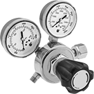
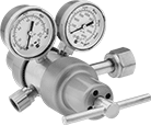
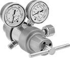
These valves automatically reduce a high inlet pressure from compressed gas tanks to a lower, stable outlet pressure. All have Compressed Gas Association (CGA) numbered inlet fittings for secure connections to compressed gas tanks. Choose a valve with the same CGA number as your tank and other system components. Valves have a gauge to monitor outlet pressure and a gauge to monitor inlet pressure from the tank.
Choose a valve with a maximum outlet pressure that’s approximately twice your application’s normal operating pressure. Your operating pressure should never exceed 75% of the valve’s maximum outlet pressure.
Single-stage valves reduce pressure in one step, which causes the outlet pressure to fluctuate slightly as you empty the tank. They’re best for applications where a constant outlet pressure isn’t critical.
Two-stage valves progressively reduce pressure over two steps for more consistent outlet pressure at all times. They’re often used in applications that require a constant outlet pressure regardless of the tank level.


Inlet | Outlet | Material | ||||||||||
|---|---|---|---|---|---|---|---|---|---|---|---|---|
| CGA Number | Location | Thread Direction | Pressure Gauge Range, psi | Location | Thread Direction | Pressure Range, psi | Pressure Adjustment Method | Body | Seal | Diaphragm | Each | |
For Use With Argon, Helium, and Nitrogen | ||||||||||||
9/16"-18 UNF Male Outlet × NGO Male Inlet | ||||||||||||
| CGA 580 | Side | Right Hand | 0 to 4,000 | Side | Right Hand | 0 to 145 | Knob | Brass/Steel | PTFE | Rubber | 0000000 | 0000000 |
For Use With Oxygen | ||||||||||||
9/16"-18 UNF Male Outlet × NGO Female Inlet | ||||||||||||
| CGA 540 | Side | Right Hand | 0 to 4,000 | Side | Right Hand | 0 to 145 | Knob | Brass/Steel | PTFE | Rubber | 0000000 | 000000 |
For Use With Air | ||||||||||||
1/4 NPT Male Outlet × NGO Male Inlet | ||||||||||||
| CGA 590 | Side | Left Hand | 0 to 4,000 | Side | Right Hand | 0 to 145 | Knob | Brass/Steel | PTFE | Rubber | 0000000 | 000000 |


Inlet | Outlet | Material | ||||||||||
|---|---|---|---|---|---|---|---|---|---|---|---|---|
| CGA Number | Location | Thread Direction | Pressure Gauge Range, psi | Location | Thread Direction | Pressure Range, psi | Pressure Adjustment Method | Body | Seal | Diaphragm | Each | |
For Use With Argon, Helium, and Nitrogen | ||||||||||||
5/8"-18 UNF Female Outlet × NGO Male Inlet | ||||||||||||
| CGA 580 | Side | Right Hand | 0 to 4,000 | Side | Right Hand | 0 to 125 | T-Handle | Brass/Steel | PTFE | Rubber | 0000000 | 0000000 |
For Use With Carbon Dioxide | ||||||||||||
5/8"-18 UNF Female Outlet × NGO Female Inlet | ||||||||||||
| CGA 320 | Side | Right Hand | 0 to 4,000 | Side | Right Hand | 0 to 125 | T-Handle | Brass/Steel | PTFE | Rubber | 0000000 | 000000 |
For Use With Oxygen | ||||||||||||
9/16"-18 UNF Male Outlet × NGO Female Inlet | ||||||||||||
| CGA 540 | Side | Right Hand | 0 to 4,000 | Side | Right Hand | 0 to 125 | T-Handle | Brass/Steel | PTFE | Rubber | 000000 | 000000 |
Tank-Mount Pressure-Regulating Valves for Fuel Gases
- For Use With: See Table
- Temperature Range: -20° to 120° F
Attach these valves to acetylene, hydrogen, methane, propane, or propylene tanks to reduce a high inlet pressure to a lower, stable outlet pressure. They have Compressed Gas Association (CGA) numbered inlet fittings for secure connections to compressed gas tanks. Choose a valve with the same CGA number as your tank and other system components. Valves come with a gauge to monitor outlet pressure and a gauge to monitor inlet pressure from the tank.
Choose a valve with a maximum outlet pressure that’s approximately twice your application’s normal operating pressure. Your operating pressure should never exceed 75% of the valve’s maximum outlet pressure.
Single-stage valves reduce pressure in one step, which causes the outlet pressure to fluctuate slightly as you empty the tank. They’re best for applications where a constant outlet pressure isn’t critical.
Two-stage valves progressively reduce pressure over two steps for more consistent outlet pressure at all times. They’re often used in applications that require a constant outlet pressure regardless of the tank level.


Inlet | Outlet | Material | |||||||||||
|---|---|---|---|---|---|---|---|---|---|---|---|---|---|
| CGA Number | Location | Thread Direction | Pressure Gauge Range, psi | Thread Size | Location | Thread Direction | Pressure Range, psi | Pressure Adjustment Method | Body | Seal | Diaphragm | Each | |
For Use With Acetylene | |||||||||||||
UNF Male Outlet × NGO Female Inlet | |||||||||||||
| CGA 300 | Side | Right Hand | 0 to 400 | 9/16"-18 | Side | Left Hand | 0 to 15 | Knob | Brass/Steel | PTFE | Rubber | 0000000 | 0000000 |
UNF Male Outlet × NGO Male Inlet | |||||||||||||
| CGA 510 | Side | Left Hand | 0 to 400 | 9/16"-18 | Side | Left Hand | 0 to 15 | Knob | Brass/Steel | PTFE | Rubber | 0000000 | 000000 |
For Use With Propane and Propylene | |||||||||||||
UNF Male Outlet × NGO Male Inlet | |||||||||||||
| CGA 510 | Side | Left Hand | 0 to 400 | 9/16"-18 | Side | Left Hand | 5 to 50 | Knob | Brass/Steel | PTFE | Rubber | 0000000 | 000000 |


Inlet | Outlet | Material | |||||||||||
|---|---|---|---|---|---|---|---|---|---|---|---|---|---|
| CGA Number | Location | Thread Direction | Pressure Gauge Range, psi | Thread Size | Location | Thread Direction | Pressure Range, psi | Pressure Adjustment Method | Body | Seal | Diaphragm | Each | |
For Use With Acetylene | |||||||||||||
UNF Male Outlet × NGO Female Inlet | |||||||||||||
| CGA 300 | Side | Right Hand | 0 to 400 | 9/16"-18 | Side | Left Hand | 0 to 15 | T-Handle | Brass/Steel | PTFE | Rubber | 000000 | 0000000 |
UNF Male Outlet × NGO Male Inlet | |||||||||||||
| CGA 510 | Side | Left Hand | 0 to 400 | 9/16"-18 | Side | Left Hand | 0 to 15 | T-Handle | Brass/Steel | PTFE | Rubber | 0000000 | 000000 |
For Use With Propane and Propylene | |||||||||||||
UNF Male Outlet × NGO Male Inlet | |||||||||||||
| CGA 510 | Side | Left Hand | 0 to 400 | 9/16"-18 | Side | Left Hand | 0 to 50 | T-Handle | Brass/Steel | PTFE | Rubber | 0000000 | 000000 |
Compact Pressure-Relief Valves
Due to their small size, these valves are often installed on tanks in low-clearance areas. They begin opening at the set pressure. Nylon valves fully open at about 10% over the set pressure and steel valves fully open at about 50% over the set pressure. Valves begin closing as pressure drops and fully close when the system pressure is restored below the set pressure. All have a vent outlet to exhaust discharge directly. Set pressure is not adjustable.
For technical drawings and 3-D models, click on a part number.

- For Use With: Air
- Temperature Range: Not Rated
Inlet | Each | ||||||||
|---|---|---|---|---|---|---|---|---|---|
| Pipe Size | Location | Maximum Pressure, psi | Relief Port Location | Overall Ht. | Specifications Met | Set Pressure, psi | 1-9 | 10-Up | |
NPTF Male Inlet and Relief Vent | |||||||||
| 1/8 | Bottom | 1 | Top | 1/2" | MS35670 | 0.3 | 0000000 | 00000 | 00000 |
| 1/4 | Bottom | Not Rated | Top | 1 1/8" | __ | 1 | 0000000 | 00000 | 00000 |
| 1/4 | Bottom | Not Rated | Top | 1 1/8" | __ | 7.5 | 0000000 | 00000 | 00000 |
| 1/4 | Bottom | Not Rated | Top | 1 1/8" | __ | 15 | 0000000 | 00000 | 00000 |
| 3/8 | Bottom | Not Rated | Top | 1 3/16" | __ | 1 | 0000000 | 00000 | 00000 |
| 3/8 | Bottom | Not Rated | Top | 1 3/16" | __ | 7.5 | 0000000 | 00000 | 00000 |
| 1/2 | Bottom | Not Rated | Top | 1 3/8" | __ | 1 | 0000000 | 00000 | 00000 |
| 1/2 | Bottom | Not Rated | Top | 1 3/8" | __ | 7.5 | 0000000 | 00000 | 00000 |

- For Use With: Grease, Oil
- Temperature Range: Not Rated
Inlet | Each | ||||||||
|---|---|---|---|---|---|---|---|---|---|
| Pipe Size | Location | Maximum Pressure, psi | Relief Port Location | Overall Ht. | Specifications Met | Set Pressure, psi | 1-9 | 10-Up | |
NPTF Male Inlet and Relief Vent | |||||||||
| 1/8 | Bottom | 5 | Top | 1/2" | MS35670 | 1 | 000000 | 00000 | 00000 |
| 1/8 | Bottom | 15 | Top | 1/2" | MS35670 | 7.5 | 000000 | 0000 | 0000 |
| 1/8 | Bottom | 25 | Top | 1/2" | MS35670 | 15 | 000000 | 0000 | 0000 |
| 1/8 | Bottom | 80 | Top | 1/2" | MS35670 | 45 | 000000 | 0000 | 0000 |
| 1/8 | Bottom | 140 | Top | 9/16" | MS35670 | 80 | 0000000 | 0000 | 0000 |
| 1/8 | Bottom | 200 | Top | 1/2" | MS35670 | 100 | 0000000 | 0000 | 0000 |
| 1/8 | Bottom | 650 | Top | 1/2" | MS35670 | 400 | 0000000 | 0000 | 0000 |
BSPT Male Inlet and Relief Vent | |||||||||
| 1/8 | Bottom | 1 | Top | 1/2" | __ | 0.3 | 0000000 | 0000 | 0000 |
| 1/8 | Bottom | 5 | Top | 1/2" | __ | 1 | 0000000 | 0000 | 0000 |
| 1/8 | Bottom | 80 | Top | 1/2" | __ | 45 | 0000000 | 0000 | 0000 |
Water Hammer Eliminators
Prevent knocking noises from water pipes with these eliminators. Install them close to the shut-off valve at any angle.
Eliminators that meet ANSI/ASSE 1010 have passed tests for standard performance requirements.
For technical drawings and 3-D models, click on a part number.

Inlet | ||||||||
|---|---|---|---|---|---|---|---|---|
| Hose Size | Gender | Max. Pressure, psi | Dia. | Ht. | Max. Temp., °F | Specifications Met | Each | |
| 3/4 | Male | 250 | 7/8" | 5" | 250° | ANSI/ASSE 1010 | 00000000 | 000000 |

Inlet | ||||||||
|---|---|---|---|---|---|---|---|---|
| Hose Size | Gender | Max. Pressure, psi | Dia. | Ht. | Max. Temp., °F | Specifications Met | Each | |
| 3/4 | Male | 250 | 7/8" | 4 1/4" | 350° | ANSI/ASSE 1010 | 00000000 | 000000 |
Filters for Supplied-Air Respirators for Plant Air Lines

Remove moisture, odors, and particles from your compressed air line before they reach respirators. These filters have a seven-stage purification process that captures particles as small as 0.5 microns. The mounting bracket doubles as a carrying handle to move them between air connection points in your facility.
To meet the OSHA standard for Grade D breathable air, these filters must be used with a carbon monoxide monitor to confirm that CO levels are safe. Replace filter inserts after five hundred hours of run time or if there’s a drop in pressure.
Filters | |||||||||||||||
|---|---|---|---|---|---|---|---|---|---|---|---|---|---|---|---|
Inlet | Outlet | Overall | Replacement Filter Inserts | ||||||||||||
| For Use With | No. of | Pipe Size | No. of | Pipe Size | Max. Flow Rate | Max. Pressure, psi | Max. Temp., °F | Removes Particle Size Down To, microns | Dia. | Ht. | Features | Each | Each | ||
NPT Female Inlet and Outlet | |||||||||||||||
Powder-Coated Steel Housing with Manual Drain | |||||||||||||||
| Solid Particles | 1 | 1 | 2 | 3/8 | 75 cfm @ 100 psi | 100 | 140° | 0.5 | 9 1/2" | 22" | Mounting Bracket | 00000000 | 0000000 | 00000000 | 000000 |


