


About Gears
More
About Roller Chain and Sprockets
More
Sprockets for Metric Roller Chain
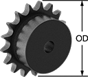
Designed to meet ISO 606 and DIN 8187 international dimensional standards, these sprockets are for use with compatible ISO and DIN roller chain. They come machined to the shaft diameter size listed and are machinable up to the maximum shaft diameter size.
![]() For technical drawings and 3-D models, click on a part number.
For technical drawings and 3-D models, click on a part number.
Quick-Grip Screw-Clamp Bushings

Also known as Trantorque bushings, these tighten with a twist of the collar nut—no screws needed. As you tighten the collar nut, the inner sleeve contracts onto the shaft and the outer sleeve expands to hold your sprocket, pulley, or gear.
![]() For technical drawings and 3-D models, click on a part number.
For technical drawings and 3-D models, click on a part number.
| For Shaft Dia. | OD | Overall Wd. | Max. Torque, in.-lbs. | Each | |
Steel | |||||
|---|---|---|---|---|---|
| 5mm | 16mm | 19mm | 140 | 000000 | 000000 |
High-Strength Corrosion-Resistant HTD Timing Belt Pulleys
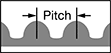
Move belts forward and backward or stop and start them in precise positions, especially in areas where rust is a concern. The curved teeth on these high-torque drive (HTD) pulleys have more surface contact with belts than traditional trapezoidal teeth, which allows you to apply more torque without damaging belts. These teeth fit together seamlessly to prevent backlash, or unwanted movement of the belt on the pulley, for a smooth, quiet cycle. These pulleys are often used in 3D printing, machine tool drives, robotics, and other applications where precision is essential. They are also known as curvilinear belt pulleys.
Pair pulleys with an HTD timing belt that has the same pitch. The width of your belt should not be larger than the maximum belt width listed.
Aluminum pulleys will not rust in damp or humid environments, but water left on the surface will cause them to corrode.
![]() For technical drawings and 3-D models, click on a part number.
For technical drawings and 3-D models, click on a part number.


| OD, mm | Number of Teeth | Pitch, mm | For Shaft Dia. | Bore Type | Inside Wd., mm | Outside Wd., mm | Overall Wd., mm | Pitch Dia., mm | Number of Flanges | Fabrication | Hub Dia., mm | Manufacturer Series | Each | |
For 6 mm Max. Belt Wd. | ||||||||||||||
|---|---|---|---|---|---|---|---|---|---|---|---|---|---|---|
| 13.9 | 16 | 2 | 5mm | Finished | 7 | 8.2 | 15.5 | 9.68 | 1 | Machined | 13.9 | Gates PowerGrip 2GT | 0000000 | 00000 |
| 15 | 20 | 2 | 5mm | Finished | 7 | 8.2 | 16 | 12.22 | 1 | Machined | 15 | Gates PowerGrip 2GT | 0000000 | 0000 |
For 9 mm Max. Belt Wd. | ||||||||||||||
| 15 | 20 | 2 | 5mm | Finished | 11 | 12.2 | 20 | 12.22 | 1 | Machined | 15 | Gates PowerGrip 2GT | 0000000 | 0000 |
For 12 mm Max. Belt Wd. | ||||||||||||||
| 15 | 20 | 2 | 5mm | Finished | 13 | 14.5 | 22 | 12.22 | 1 | Machined | 15 | Gates PowerGrip 2GT | 0000000 | 0000 |
High-Strength HTD Timing Belt Idler Pulleys
Keep high torque drive (HTD) timing belt systems running tightly with these idler pulleys. Made with built-in, free-spinning ball bearings, they're installed on shafts or belt tensioners (not included) to remove slack from timing belts. By maintaining tension on the belt, these pulleys reduce wear and vibration in 3D printing, machine tool drives, robotics, and other linear motion applications that require precise positioning.
When replacing an idler pulley, be sure the pulley matches your belt's trade size.
Toothed pulleys are shaped to mesh with the teeth on a timing belt, which reduces wear on the belt's teeth.
![]() For technical drawings and 3-D models, click on a part number.
For technical drawings and 3-D models, click on a part number.


| Manufacturer Series | OD | Number of Teeth | For Shaft Dia. | Dia. | Wd. | Groove Dp. | Shaft Mount Type | Bore Type | Number of Flanges | Fabrication | Material | Bearing Type | Each | |
For 6 mm Max. Belt Wd. | ||||||||||||||
|---|---|---|---|---|---|---|---|---|---|---|---|---|---|---|
| Gates PowerGrip 2GT | 15mm | 20 | 5mm | 12.22mm | 10mm | 1.39 mm | Slip Fit | Finished | 2 | Machined | Aluminum | Ball | 0000000 | 00000 |
For 9 mm Max. Belt Wd. | ||||||||||||||
| Gates PowerGrip 2GT | 15mm | 20 | 5mm | 12.22mm | 14mm | 1.39 mm | Slip Fit | Finished | 2 | Machined | Aluminum | Ball | 0000000 | 0000 |
For 12 mm Max. Belt Wd. | ||||||||||||||
| Gates PowerGrip 2GT | 15mm | 20 | 5mm | 12.22mm | 16mm | 1.39 mm | Slip Fit | Finished | 2 | Machined | Aluminum | Ball | 0000000 | 0000 |
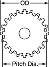
Metal Gears and Gear Racks—20° Pressure Angle
The current industry standard, these 20° pressure angle gears have thicker, stronger teeth than 14½° pressure angle gears. Compared to plastic gears and racks, they’re better for high-load, high-speed, and heavy duty applications. Also known as spur gears.
Combine gears with different numbers of teeth to change speed and torque in your assembly. Combine a gear and rack to convert rotary motion into linear motion. To minimize your footprint, mount one or more standard gears inside of an internal gear.
For components to mesh correctly, they must have the same pressure angle and pitch/module.
Brass gears and racks are easy to machine, so you can add your own mounting holes and make other alterations. They won't rust when exposed to water.
Carbon steel components have hard, strong, and wear-resistant teeth, although they will rust when exposed to moisture and corrosive chemicals. They're best for high-torque machines, like lifting equipment, and heavy duty applications, such as rock crushing. Gears with teeth that are not hardened can be hardened to fit your application.
Stainless steel gears and racks resist rust in damp and wet environments, so they're commonly used in food-processing plants and other areas with frequent cleaning. Gears with a clamping bore have a built-in clamp that securely grips shafts without marring them. Use the included clamping screw to tighten or loosen the grip.
![]() For technical drawings and 3-D models, click on a part number.
For technical drawings and 3-D models, click on a part number.


Hub | ||||||||||||||
|---|---|---|---|---|---|---|---|---|---|---|---|---|---|---|
| Module | Number of Teeth | Gear Pitch Dia., mm | OD, mm | Face Wd., mm | Overall Wd., mm | For Shaft Dia., mm | Material | Teeth Heat Treatment | Dia., mm | Wd., mm | Set Screw Thread Size | Clamping Screw Thread Size | Each | |
Round Bore | ||||||||||||||
| 0.8 | 20 | 16 | 17.6 | 4 | 12 | 5 | Brass | __ | 13 | 8 | __ | __ | 00000000 | 000000 |
Round Bore with Set Screw | ||||||||||||||
| 0.5 | 24 | 12 | 13 | 5 | 16 | 5 | Black-Oxide 1045 Carbon Steel | Not Hardened | 13 | 11 | M4 | __ | 00000000 | 00000 |
| 0.5 | 36 | 18 | 19 | 5 | 12 | 5 | Black-Oxide 1045 Carbon Steel | Not Hardened | 16 | 7 | M4 | __ | 00000000 | 00000 |
| 0.5 | 45 | 22.5 | 23.5 | 5 | 12 | 5 | Black-Oxide 1045 Carbon Steel | Not Hardened | 20 | 7 | M4 | __ | 00000000 | 00000 |
| 0.5 | 50 | 25 | 26 | 5 | 12 | 5 | Black-Oxide 1045 Carbon Steel | Not Hardened | 22 | 7 | M4 | __ | 00000000 | 00000 |
| 0.5 | 55 | 27.5 | 28 | 5 | 12 | 5 | Black-Oxide 1045 Carbon Steel | Not Hardened | 25 | 7 | M4 | __ | 00000000 | 00000 |
| 0.8 | 16 | 12.8 | 14.4 | 8 | 22 | 5 | Black-Oxide 1045 Carbon Steel | Not Hardened | 14.4 | 14 | M4 | __ | 00000000 | 00000 |
| 0.8 | 20 | 16 | 17.6 | 8 | 16 | 5 | Black-Oxide 1045 Carbon Steel | Not Hardened | 13 | 8 | M4 | __ | 00000000 | 00000 |
| 0.8 | 21 | 16.8 | 18.4 | 4 | 12 | 5 | Brass | __ | 14 | 8 | M4 | __ | 00000000 | 00000 |
| 0.8 | 23 | 18.4 | 20 | 4 | 12 | 5 | Brass | __ | 15 | 8 | M4 | __ | 00000000 | 00000 |
| 0.8 | 24 | 19.2 | 20.8 | 4 | 12 | 5 | Brass | __ | 16 | 8 | M4 | __ | 00000000 | 00000 |
| 0.8 | 24 | 19.2 | 20.8 | 8 | 16 | 5 | Black-Oxide 1045 Carbon Steel | Not Hardened | 16 | 8 | M4 | __ | 00000000 | 00000 |
| 0.8 | 25 | 20 | 21.6 | 8 | 16 | 5 | Black-Oxide 1045 Carbon Steel | Not Hardened | 16 | 8 | M4 | __ | 00000000 | 00000 |
| 0.8 | 26 | 20.8 | 22.4 | 4 | 12 | 5 | Brass | __ | 18 | 8 | M4 | __ | 00000000 | 00000 |
| 0.8 | 32 | 25.6 | 27.2 | 4 | 12 | 5 | Brass | __ | 22 | 8 | M4 | __ | 00000000 | 00000 |
| 0.8 | 36 | 28.8 | 30.4 | 4 | 12 | 5 | Brass | __ | 25 | 8 | M4 | __ | 00000000 | 00000 |
| 0.8 | 40 | 32 | 33.6 | 4 | 12 | 5 | Brass | __ | 28 | 8 | M4 | __ | 00000000 | 00000 |
| 0.8 | 60 | 48 | 49.6 | 4 | 12 | 5 | Brass | __ | 28 | 8 | M4 | __ | 00000000 | 00000 |
| 1 | 16 | 16 | 18 | 6 | 14 | 5 | Brass | __ | 12 | 8 | M4 | __ | 00000000 | 00000 |
| 1 | 16 | 16 | 18 | 10 | 30 | 5 | Black-Oxide 1045 Carbon Steel | Not Hardened | 18 | 20 | M4 | __ | 00000000 | 00000 |
| 1 | 20 | 20 | 22 | 10 | 20 | 5 | Black-Oxide 1045 Carbon Steel | Not Hardened | 16 | 10 | M4 | __ | 00000000 | 00000 |
| 1 | 30 | 30 | 32 | 6 | 14 | 5 | Brass | __ | 25 | 8 | M4 | __ | 00000000 | 00000 |
| 1 | 32 | 32 | 34 | 6 | 14 | 5 | Brass | __ | 28 | 8 | M4 | __ | 00000000 | 00000 |
Clamping Bore with Clamping Screw | ||||||||||||||
| 0.5 | 24 | 12 | 13.5 | 7 | 22 | 5 | 303 Stainless Steel | Not Hardened | 14 | 8 | __ | M2.5 | 0000000 | 00000 |
Metal Worms and Worm Gears

Worm gears use screw threads to make large reductions to shaft speed while transmitting motion at a right angle. They transmit motion from worm to gear and cannot be reversed. For gears and worms to mesh correctly, they must have the same pressure angle, pitch/module, number of thread starts, and thread direction. These worms are compatible with plastic worm gears.
Speed ratio is the ratio by which output shaft speed is reduced. As speed decreases, torque increases.
1045 carbon steel worms have rolled threads. 303 stainless steel worms won’t rust in wet environments, so they’re commonly used in food-processing plants and other areas with frequent cleaning.
Bronze gears have low friction and dissipate heat better than cast iron gears to provide a long service life for both the gear and the worm. They’re also more corrosion resistant than cast iron gears.
![]() For technical drawings and 3-D models, click on a part number.
For technical drawings and 3-D models, click on a part number.

| Module | Pressure Angle | Worm Lg., mm | Gear Pitch Dia., mm | OD, mm | For Shaft Dia., mm | Number of Thread Starts | Thread Direction | Teeth Heat Treatment | Teeth Fabrication | Set Screw Included | Each | |
Round Bore—Black-Oxide 1045 Carbon Steel | ||||||||||||
|---|---|---|---|---|---|---|---|---|---|---|---|---|
| 0.5 | 20° | 18 | 11 | 12 | 5 | 1 | Right Hand | Not Hardened | Not Ground | Yes | 000000000 | 000000 |
| 0.5 | 20° | 18 | 11 | 12 | 5 | 2 | Right Hand | Not Hardened | Not Ground | Yes | 000000000 | 00000 |
Round Bore—303 Stainless Steel | ||||||||||||
| 0.5 | 20° | 18 | 11 | 12 | 5 | 1 | Right Hand | Not Hardened | Not Ground | Yes | 000000000 | 00000 |
| 0.5 | 20° | 18 | 11 | 12 | 5 | 2 | Right Hand | Not Hardened | Not Ground | Yes | 000000000 | 00000 |


Hub | |||||||||||||||||
|---|---|---|---|---|---|---|---|---|---|---|---|---|---|---|---|---|---|
| Module | Speed Ratio | Number of Teeth | Pressure Angle | Gear Pitch Dia., mm | For Number of Thread Starts | OD, mm | Face Wd., mm | Overall Wd., mm | For Shaft Dia., mm | Dia., mm | Wd., mm | Material | For Thread Direction | Teeth Heat Treatment | Teeth Fabrication | Each | |
Round Bore—Bronze | |||||||||||||||||
| 0.5 | 40:1 | 40 | 20° | 20 | 1 | 21 | 5 | 12 | 5 | 15 | 7 | Bronze | Right Hand | Not Hardened | Not Ground | 000000000 | 000000 |
| 0.5 | 50:1 | 50 | 20° | 25 | 1 | 26 | 5 | 12 | 5 | 20 | 7 | Bronze | Right Hand | Not Hardened | Not Ground | 000000000 | 00000 |
| 0.5 | 60:1 | 60 | 20° | 30 | 1 | 31 | 5 | 12 | 5 | 25 | 7 | Bronze | Right Hand | Not Hardened | Not Ground | 000000000 | 00000 |
| 0.8 | 20:1 | 20 | 20° | 16 | 1 | 17.6 | 9 | 18 | 5 | 12 | 9 | Bronze | Right Hand | Not Hardened | Not Ground | 000000000 | 00000 |
| 0.8 | 30:1 | 30 | 20° | 24 | 1 | 25.6 | 9 | 18 | 5 | 18 | 9 | Bronze | Right Hand | Not Hardened | Not Ground | 000000000 | 00000 |
| 0.8 | 10:1 | 20 | 20° | 16 | 2 | 17.6 | 9 | 18 | 5 | 12 | 9 | Bronze | Right Hand | Not Hardened | Not Ground | 000000000 | 00000 |
Plastic Gears and Gear Racks—20° Pressure Angle
The current industry standard, these 20° pressure angle gears have thicker, stronger teeth than 14½° pressure angle gears. Made of plastic, they run quieter than metal gears and have good corrosion and chemical resistance. They’re also known as spur gears.
Combine gears with different numbers of teeth to change speed and torque in your assembly. Combine a gear and rack to convert rotary motion into linear motion.
For components to mesh correctly, they must have the same pressure angle and pitch/module.
Acetal gears are best suited for use in light duty machines or for prototyping.
![]() For technical drawings and 3-D models, click on a part number.
For technical drawings and 3-D models, click on a part number.

Hub | |||||||||||||
|---|---|---|---|---|---|---|---|---|---|---|---|---|---|
| Module | Number of Teeth | Gear Pitch Dia., mm | OD, mm | Face Wd., mm | Overall Wd., mm | For Shaft Dia., mm | Material | Fabrication | Color | Dia., mm | Wd., mm | Each | |
Round Bore | |||||||||||||
| 0.5 | 30 | 15 | 16 | 3 | 7 | 5 | Acetal Plastic | Molded | White | 10 | 4 | 00000000 | 00000 |
| 0.5 | 36 | 18 | 19 | 3 | 7 | 5 | Acetal Plastic | Molded | White | 10 | 4 | 0000000 | 0000 |
| 0.5 | 40 | 20 | 21 | 3 | 7 | 5 | Acetal Plastic | Molded | White | 12 | 4 | 00000000 | 0000 |
| 0.5 | 45 | 22.5 | 23.5 | 3 | 7 | 5 | Acetal Plastic | Molded | White | 12 | 4 | 00000000 | 0000 |
| 0.5 | 48 | 24 | 25 | 3 | 7 | 5 | Acetal Plastic | Molded | White | 12 | 4 | 0000000 | 0000 |
| 0.5 | 50 | 25 | 26 | 3 | 7 | 5 | Acetal Plastic | Molded | White | 12 | 4 | 00000000 | 0000 |
| 0.8 | 20 | 16 | 17.6 | 4 | 9 | 5 | Acetal Plastic | Molded | White | 10 | 5 | 0000000 | 0000 |
| 0.8 | 24 | 19.2 | 20.8 | 4 | 9 | 5 | Acetal Plastic | Molded | White | 10 | 5 | 00000000 | 0000 |
| 1 | 16 | 16 | 18 | 6 | 12 | 5 | Acetal Plastic | Molded | White | 10 | 6 | 00000000 | 0000 |
| 1 | 18 | 18 | 20 | 6 | 12 | 5 | Acetal Plastic | Molded | White | 10 | 6 | 00000000 | 0000 |
| 1 | 20 | 20 | 22 | 6 | 12 | 5 | Acetal Plastic | Molded | White | 11.7 | 6 | 0000000 | 0000 |
| 1 | 24 | 24 | 26 | 6 | 12 | 5 | Acetal Plastic | Molded | White | 11.7 | 6 | 00000000 | 0000 |
| 1 | 28 | 28 | 30 | 6 | 12 | 5 | Acetal Plastic | Molded | White | 11.7 | 6 | 00000000 | 0000 |
Plastic Miter Gears

Connect two shafts at a right angle without changing shaft speed or torque. Made of plastic, these gears run quieter than metal gears and have good corrosion and chemical resistance.
For two gears to mesh correctly, they must have the same pressure angle, pitch/module, and number of teeth.
Acetal gears absorb less moisture than nylon gears and are less prone to dimensional change. They’re best suited for use in light duty applications such as prototyping.
![]() For technical drawings and 3-D models, click on a part number.
For technical drawings and 3-D models, click on a part number.

Hub | |||||||||||||||
|---|---|---|---|---|---|---|---|---|---|---|---|---|---|---|---|
| Module | Number of Teeth | Pressure Angle | Gear Pitch Dia. | OD, mm | Face Wd., mm | Overall Wd., mm | For Shaft Dia., mm | Mounting Distance, mm | Material | Fabrication | Color | Dia., mm | Wd., mm | Each | |
Round Bore | |||||||||||||||
| 0.8 | 20 | 20° | 16mm | 17.1 | 3.5 | 10.8 | 5 | 16 | Acetal Plastic | Molded | White | 12 | 5 | 000000 | 00000 |
Plastic Worm Gears

These plastic gears are lighter and quieter than metal gears—pair them with metal worms for lubrication-free operation. Worm gears use screw threads to make large reductions to shaft speed while transmitting motion at a right angle. They transmit motion from worm to gear and cannot be reversed. For gears and worms to mesh correctly, they must have the same pressure angle, pitch/module, number of thread starts, and thread direction.
Speed ratio is the ratio by which output shaft speed is reduced. As speed decreases, torque increases.
Acetal gears are lightweight, and resist corrosion and chemicals. They absorb less moisture than nylon gears, so they’re less prone to dimensional changes. They’re best suited for light duty applications, such as prototyping.
![]() For technical drawings and 3-D models, click on a part number.
For technical drawings and 3-D models, click on a part number.
Hub | |||||||||||||||||
|---|---|---|---|---|---|---|---|---|---|---|---|---|---|---|---|---|---|
| Module | Speed Ratio | Number of Teeth | Pressure Angle | Gear Pitch Dia., mm | For Number of Thread Starts | OD, mm | Face Width, mm | Overall Width, mm | For Shaft Diameter, mm | Material | Fabrication | Color | Diameter, mm | Width, mm | For Thread Direction | Each | |
Round Bore | |||||||||||||||||
| 0.5 | 40:1 | 40 | 20° | 20 | 1 | 21 | 5 | 12 | 5 | Acetal Plastic | Molded | White | 15 | 7 | Right Hand | 00000000 | 000000 |
| 0.5 | 50:1 | 50 | 20° | 25 | 1 | 26 | 5 | 12 | 5 | Acetal Plastic | Molded | White | 20 | 7 | Right Hand | 00000000 | 00000 |
| 0.5 | 60:1 | 60 | 20° | 30 | 1 | 31 | 5 | 12 | 5 | Acetal Plastic | Molded | White | 25 | 7 | Right Hand | 00000000 | 00000 |
| 0.8 | 10:1 | 20 | 20° | 16 | 2 | 17.6 | 9 | 18 | 5 | Acetal Plastic | Molded | White | 12 | 9 | Right Hand | 00000000 | 00000 |
Metal Ratcheting Gears

Compared to plastic gears, these metal ratcheting gears are better for high-load, high-speed, and heavy duty applications. Used to prevent unwanted motion in jacks, tie downs, clutches, and winches, ratchet gears have sloped teeth that allow motion in one direction and prevent it in the other.
A pawl is required to prevent backward motion.
![]() For technical drawings and 3-D models, click on a part number.
For technical drawings and 3-D models, click on a part number.


| For Face Wd. | For Shaft Dia. | Overall Lg. | Material | Center-to-End Lg. | Each | |
Round Bore | ||||||
|---|---|---|---|---|---|---|
| 6mm | 5mm | 38mm | 1045 Carbon Steel | 30mm | 0000000 | 000000 |