


About Gears
More
Quick-Grip Screw-Clamp Bushings

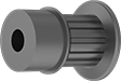
Also known as Trantorque bushings, these tighten with a twist of the collar nut—no screws needed. As you tighten the collar nut, the inner sleeve contracts onto the shaft and the outer sleeve expands to hold your sprocket, pulley, or gear.
![]() For technical drawings and 3-D models, click on a part number.
For technical drawings and 3-D models, click on a part number.
| For Shaft Dia. | OD | Overall Wd. | Max. Torque, in.-lbs. | Each | |
Steel | |||||
|---|---|---|---|---|---|
| 4mm | 16mm | 19mm | 120 | 0000000 | 000000 |
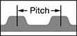
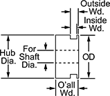
MXL Series Corrosion-Resistant Timing Belt Pulleys
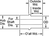
Anodized aluminum has good corrosion resistance. Pulleys are MXL series (miniature extra light) and have trapezoidal teeth. The teeth match up with the grooves along the inside diameter of a timing belt in order to move components forward or backward. Select a pulley with a maximum belt width that’s the same or larger than your timing belt width.
![]() For technical drawings and 3-D models, click on a part number.
For technical drawings and 3-D models, click on a part number.


| OD | Number of Teeth | Pitch | For Shaft Dia. | Bore Type | Inside Wd. | Outside Wd. | Overall Wd. | Pitch Dia. | Number of Flanges | Fabrication | Material | Hub Dia. | Each | |
For 3 mm Max. Belt Wd. | ||||||||||||||
|---|---|---|---|---|---|---|---|---|---|---|---|---|---|---|
| 14.1mm | 15 | 2.030mm | 4mm | Finished | 4mm | 5.1mm | 11.1mm | 9.7mm | 1 | Machined | Anodized Aluminum | 14.1mm | 00000000 | 000000 |
| 14.7mm | 16 | 2.030mm | 4mm | Finished | 4mm | 5.1mm | 11.1mm | 10.3mm | 1 | Machined | Anodized Aluminum | 14.7mm | 00000000 | 00000 |
| 16.1mm | 18 | 2.030mm | 4mm | Finished | 4mm | 6.6mm | 12.3mm | 11.6mm | 2 | Machined | Anodized Aluminum | 7.9mm | 00000000 | 00000 |
| 17.4mm | 20 | 2.030mm | 4mm | Finished | 4mm | 6.6mm | 12.3mm | 12.9mm | 2 | Machined | Anodized Aluminum | 9.2mm | 00000000 | 00000 |
| 18.8mm | 22 | 2.030mm | 4mm | Finished | 4mm | 6.6mm | 12.3mm | 14.2mm | 2 | Machined | Anodized Aluminum | 9.9mm | 00000000 | 00000 |
For 6 mm Max. Belt Wd. | ||||||||||||||
| 14.1mm | 15 | 2.030mm | 4mm | Finished | 7.2mm | 8.3mm | 14.3mm | 9.7mm | 1 | Machined | Anodized Aluminum | 14.1mm | 00000000 | 00000 |
| 14.7mm | 16 | 2.030mm | 4mm | Finished | 7.2mm | 8.3mm | 14.3mm | 10.3mm | 1 | Machined | Anodized Aluminum | 14.7mm | 00000000 | 00000 |
| 16.1mm | 18 | 2.030mm | 4mm | Finished | 7.2mm | 9.9mm | 15.9mm | 11.6mm | 2 | Machined | Anodized Aluminum | 7.9mm | 00000000 | 00000 |
| 17.4mm | 20 | 2.030mm | 4mm | Finished | 7.2mm | 9.9mm | 15.9mm | 12.9mm | 2 | Machined | Anodized Aluminum | 9.2mm | 00000000 | 00000 |
| 18.8mm | 22 | 2.030mm | 4mm | Finished | 7.2mm | 9.9mm | 15.9mm | 14.2mm | 2 | Machined | Anodized Aluminum | 9.9mm | 00000000 | 00000 |
For 9 mm Max. Belt Wd. | ||||||||||||||
| 14.1mm | 15 | 2.030mm | 4mm | Finished | 10.4mm | 11.5mm | 17.5mm | 9.7mm | 1 | Machined | Anodized Aluminum | 14.1mm | 00000000 | 00000 |
| 14.7mm | 16 | 2.030mm | 4mm | Finished | 10.4mm | 11.5mm | 17.5mm | 10.3mm | 1 | Machined | Anodized Aluminum | 14.7mm | 00000000 | 00000 |
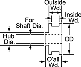
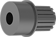
MXL Series Lightweight Timing Belt Pulleys
Made from polycarbonate, these pulleys are useful in applications with weight constraints. All are MXL series (miniature extra light) and have trapezoidal teeth. The teeth match up with the grooves along the inside diameter of a timing belt in order to move components forward or backward. Select a pulley with a maximum belt width that’s the same or larger than your timing belt width.
![]() For technical drawings and 3-D models, click on a part number.
For technical drawings and 3-D models, click on a part number.
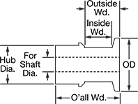
| OD | Number of Teeth | Pitch | For Shaft Dia. | Bore Type | Inside Wd. | Outside Wd. | Overall Wd. | Pitch Dia. | Fabrication | Material | Hub Dia. | Each | |
1 Flange | |||||||||||||
|---|---|---|---|---|---|---|---|---|---|---|---|---|---|
For 6 mm Max. Belt Wd. | |||||||||||||
| 13mm | 14 | 2.030mm | 4mm | Finished | 9.5mm | 15.9mm | 17.5mm | 9.1mm | Molded | Polycarbonate | 11mm | 0000000 | 00000 |
2 Flanges | |||||||||||||
For 6 mm Max. Belt Wd. | |||||||||||||
| 13mm | 14 | 2.030mm | 4mm | Finished | 9.5mm | 15.9mm | 17.5mm | 9.1mm | Molded | Polycarbonate | 11mm | 0000000 | 00000 |
| 14mm | 15 | 2.030mm | 4mm | Finished | 9.5mm | 15.9mm | 17.5mm | 9.7mm | Molded | Polycarbonate | 11mm | 0000000 | 00000 |
| 15mm | 16 | 2.030mm | 4mm | Finished | 9.5mm | 15.9mm | 17.5mm | 10.3mm | Molded | Polycarbonate | 11mm | 0000000 | 00000 |
Metal Gears and Gear Racks—20° Pressure Angle
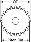
The current industry standard, these 20° pressure angle gears have thicker, stronger teeth than 14½° pressure angle gears. Compared to plastic gears and racks, they’re better for high-load, high-speed, and heavy duty applications. Also known as spur gears.
Combine gears with different numbers of teeth to change speed and torque in your assembly. Combine a gear and rack to convert rotary motion into linear motion. To minimize your footprint, mount one or more standard gears inside of an internal gear.
For components to mesh correctly, they must have the same pressure angle and pitch/module.
Brass gears and racks are easy to machine, so you can add your own mounting holes and make other alterations. They won't rust when exposed to water.
Carbon steel components have hard, strong, and wear-resistant teeth, although they will rust when exposed to moisture and corrosive chemicals. They're best for high-torque machines, like lifting equipment, and heavy duty applications, such as rock crushing. Gears with teeth that are not hardened can be hardened to fit your application.
![]() For technical drawings and 3-D models, click on a part number.
For technical drawings and 3-D models, click on a part number.


Hub | |||||||||||||
|---|---|---|---|---|---|---|---|---|---|---|---|---|---|
| Module | Number of Teeth | Gear Pitch Dia., mm | OD, mm | Face Wd., mm | Overall Wd., mm | For Shaft Dia., mm | Material | Teeth Heat Treatment | Dia., mm | Wd., mm | Set Screw Thread Size | Each | |
Round Bore | |||||||||||||
| 0.5 | 20 | 10 | 11 | 3 | 10 | 4 | Brass | __ | 8.5 | 7 | __ | 00000000 | 000000 |
| 0.5 | 25 | 12.5 | 13.5 | 3 | 10 | 4 | Brass | __ | 11 | 7 | __ | 00000000 | 00000 |
| 0.5 | 30 | 15 | 16 | 3 | 10 | 4 | Brass | __ | 13 | 7 | __ | 00000000 | 00000 |
Round Bore with Set Screw | |||||||||||||
| 0.5 | 18 | 9 | 10 | 5 | 16 | 4 | Black-Oxide 1045 Carbon Steel | Not Hardened | 10 | 11 | M3 | 00000000 | 00000 |
| 0.5 | 20 | 10 | 11 | 5 | 16 | 4 | Black-Oxide 1045 Carbon Steel | Not Hardened | 11 | 11 | M3 | 00000000 | 00000 |
| 0.5 | 24 | 12 | 13 | 3 | 10 | 4 | Brass | __ | 10 | 7 | M3 | 00000000 | 00000 |
| 0.5 | 30 | 15 | 16 | 3 | 10 | 4 | Brass | __ | 12 | 7 | M3 | 00000000 | 00000 |
| 0.5 | 30 | 15 | 16 | 5 | 12 | 4 | Black-Oxide 1045 Carbon Steel | Not Hardened | 13 | 7 | M3 | 00000000 | 00000 |
| 0.5 | 36 | 18 | 19 | 3 | 10 | 4 | Brass | __ | 16 | 7 | M3 | 00000000 | 00000 |
| 0.5 | 40 | 20 | 21 | 3 | 10 | 4 | Brass | __ | 18 | 7 | M3 | 00000000 | 00000 |
| 0.5 | 50 | 25 | 26 | 3 | 10 | 4 | Brass | __ | 22 | 7 | M3 | 00000000 | 00000 |
| 0.8 | 17 | 13.6 | 15.2 | 4 | 12 | 4 | Brass | __ | 10 | 8 | M3 | 00000000 | 00000 |
| 0.8 | 18 | 14.4 | 16 | 4 | 12 | 4 | Brass | __ | 10 | 8 | M3 | 00000000 | 00000 |
| 0.8 | 25 | 20 | 21.6 | 4 | 12 | 4 | Brass | __ | 16 | 8 | M3 | 00000000 | 00000 |
| 0.8 | 30 | 24 | 25.6 | 4 | 12 | 4 | Brass | __ | 20 | 8 | M3 | 00000000 | 00000 |
Metal Worms and Worm Gears

Worm gears use screw threads to make large reductions to shaft speed while transmitting motion at a right angle. They transmit motion from worm to gear and cannot be reversed. For gears and worms to mesh correctly, they must have the same pressure angle, pitch/module, number of thread starts, and thread direction. These worms are compatible with plastic worm gears.
Speed ratio is the ratio by which output shaft speed is reduced. As speed decreases, torque increases.
Bronze gears have low friction and dissipate heat better than cast iron gears to provide a long service life for both the gear and the worm. They’re also more corrosion resistant than cast iron gears.
![]() For technical drawings and 3-D models, click on a part number.
For technical drawings and 3-D models, click on a part number.


Hub | |||||||||||||||||
|---|---|---|---|---|---|---|---|---|---|---|---|---|---|---|---|---|---|
| Module | Speed Ratio | Number of Teeth | Pressure Angle | Gear Pitch Dia., mm | For Number of Thread Starts | OD, mm | Face Wd., mm | Overall Wd., mm | For Shaft Dia., mm | Dia., mm | Wd., mm | Material | For Thread Direction | Teeth Heat Treatment | Teeth Fabrication | Each | |
Round Bore—Bronze | |||||||||||||||||
| 0.5 | 15:1 | 30 | 20° | 15 | 2 | 16 | 5 | 12 | 4 | 12 | 7 | Bronze | Right Hand | Not Hardened | Not Ground | 000000000 | 000000 |
| 0.5 | 20:1 | 20 | 20° | 10 | 1 | 11 | 5 | 12 | 4 | 9 | 7 | Bronze | Right Hand | Not Hardened | Not Ground | 000000000 | 00000 |
| 0.5 | 30:1 | 30 | 20° | 15 | 1 | 16 | 5 | 12 | 4 | 12 | 7 | Bronze | Right Hand | Not Hardened | Not Ground | 000000000 | 00000 |
| 0.5 | 10:1 | 20 | 20° | 10 | 2 | 11 | 5 | 12 | 4 | 9 | 7 | Bronze | Right Hand | Not Hardened | Not Ground | 000000000 | 00000 |
Plastic Gears and Gear Racks—20° Pressure Angle
The current industry standard, these 20° pressure angle gears have thicker, stronger teeth than 14½° pressure angle gears. Made of plastic, they run quieter than metal gears and have good corrosion and chemical resistance. They’re also known as spur gears.
Combine gears with different numbers of teeth to change speed and torque in your assembly. Combine a gear and rack to convert rotary motion into linear motion.
For components to mesh correctly, they must have the same pressure angle and pitch/module.
Acetal gears are best suited for use in light duty machines or for prototyping.
![]() For technical drawings and 3-D models, click on a part number.
For technical drawings and 3-D models, click on a part number.

Hub | |||||||||||||
|---|---|---|---|---|---|---|---|---|---|---|---|---|---|
| Module | Number of Teeth | Gear Pitch Dia., mm | OD, mm | Face Wd., mm | Overall Wd., mm | For Shaft Dia., mm | Material | Fabrication | Color | Dia., mm | Wd., mm | Each | |
Round Bore | |||||||||||||
| 0.5 | 20 | 10 | 11 | 3 | 7 | 4 | Acetal Plastic | Molded | White | 8 | 4 | 00000000 | 00000 |
| 0.5 | 24 | 12 | 13 | 3 | 7 | 4 | Acetal Plastic | Molded | White | 8 | 4 | 0000000 | 0000 |
| 0.8 | 16 | 12.8 | 14.4 | 4 | 9 | 4 | Acetal Plastic | Molded | White | 8 | 5 | 00000000 | 0000 |
| 1 | 12 | 12 | 14 | 6 | 12 | 4 | Acetal Plastic | Molded | White | 8 | 6 | 00000000 | 0000 |
| 1 | 15 | 15 | 17 | 6 | 12 | 4 | Acetal Plastic | Molded | White | 8 | 6 | 0000000 | 0000 |
Plastic Worm Gears

These plastic gears are lighter and quieter than metal gears—pair them with metal worms for lubrication-free operation. Worm gears use screw threads to make large reductions to shaft speed while transmitting motion at a right angle. They transmit motion from worm to gear and cannot be reversed. For gears and worms to mesh correctly, they must have the same pressure angle, pitch/module, number of thread starts, and thread direction.
Speed ratio is the ratio by which output shaft speed is reduced. As speed decreases, torque increases.
Acetal gears are lightweight, and resist corrosion and chemicals. They absorb less moisture than nylon gears, so they’re less prone to dimensional changes. They’re best suited for light duty applications, such as prototyping.
![]() For technical drawings and 3-D models, click on a part number.
For technical drawings and 3-D models, click on a part number.
Hub | |||||||||||||||||
|---|---|---|---|---|---|---|---|---|---|---|---|---|---|---|---|---|---|
| Module | Speed Ratio | Number of Teeth | Pressure Angle | Gear Pitch Dia., mm | For Number of Thread Starts | OD, mm | Face Width, mm | Overall Width, mm | For Shaft Diameter, mm | Material | Fabrication | Color | Diameter, mm | Width, mm | For Thread Direction | Each | |
Round Bore | |||||||||||||||||
| 0.5 | 10:1 | 20 | 20° | 10 | 2 | 11 | 5 | 12 | 4 | Acetal Plastic | Molded | White | 9 | 7 | Right Hand | 00000000 | 000000 |
| 0.5 | 20:1 | 20 | 20° | 10 | 1 | 11 | 5 | 12 | 4 | Acetal Plastic | Molded | White | 9 | 7 | Right Hand | 00000000 | 00000 |
| 0.5 | 30:1 | 30 | 20° | 15 | 1 | 16 | 5 | 12 | 4 | Acetal Plastic | Molded | White | 12 | 7 | Right Hand | 00000000 | 00000 |