


Choosing an Electrical Switch
More
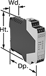
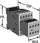
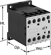
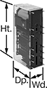
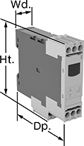
Safety Relays with Diagnostic Capabilities
Control and diagnose issues with safety-critical circuits. These relays have a microprocessor that monitors safety components, such as emergency stops and light curtains, and sends a signal to stop the operation if a failure is detected and restart when the issue is resolved. They also help with diagnostic tasks because of their feedback circuit, which allows basic relays to communicate their status back to the safety relay. These relays have a duplicate set of input and output signals, so they’ll still stop the controlled device if one of the inputs fails.
IP20 rated, they have recessed terminals which prevent fingers and other objects from touching live circuits. These relays have been tested to multiple safety standards and can help achieve PL, SIL, or CAT system ratings. They also meet ISO and IEC standards for machine safety.
Mount them to 35 mm DIN rail (also known as DIN 3 Rail) for fast installation.
Relays and auxiliary contact blocks with delayed safety outputs are often used where power must be maintained after an input signal is received. For example, after a stop button for a machine is pressed, the guard door will stay locked until the machine cycle is finished.
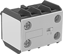
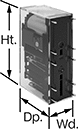
Auxiliary contact blocks (sold separately) allow you to control more components, such as signaling devices or basic relays.
![]() For technical drawings and 3-D models, click on a part number.
For technical drawings and 3-D models, click on a part number.

| Number of Terminals | Input Voltage | Switching Current @ Voltage | Max. Switching Voltage | Ht. | Wd. | Dp. | For Use With | Max. System Safety Rating | Features | Each | |
2 Circuits Controlled | |||||||||||
|---|---|---|---|---|---|---|---|---|---|---|---|
2 Off (Normally Open) | |||||||||||
| 14 | 24V DC | 2 A @ 240 V AC 1.5 A @ 24 V DC | 250V AC | 4.9" | 0.69" | 4.3" | Emergency Stops, Light Curtains | PLe, SIL3, CAT 4, 250V | Auxiliary PNP Output, LED Indicator | 0000000 | 0000000 |
2 Safety Outputs with 2 Off (Normally Open) and 2 Delayed Safety Outputs with 2 Off (Normally Open) | |||||||||||
| 16 | 24V DC | 3 A @ 240 V AC 3 A @ 24 V DC | 250V AC 250V DC | 3.9" | 0.9" | 4.5" | Emergency Stops, Light Curtains | PLe, SIL3 | Time Delay | 0000000 | 000000 |
2 Safety Outputs with 2 Off (Normally Open) and 1 Signal Output with 2 On (Normally Closed) | |||||||||||
| 16 | 24V AC, 24V DC | 5 A @ 240 V AC 5 A @ 24 V DC | 250V AC 250V DC | 3.9" | 0.9" | 4.5" | Emergency Stops | PLe, SIL3 | __ | 0000000 | 000000 |
| 16 | 24V AC, 24V DC | 5 A @ 240 V AC 5 A @ 24 V DC | 250V AC 250V DC | 3.9" | 0.9" | 4.5" | Two-Hand Switches | PLe, SIL3 | __ | 0000000 | 000000 |
3 Safety Outputs with 2 Off (Normally Open) and 1 Signal Output with 2 On (Normally Closed) | |||||||||||
| 16 | 240V AC | 3 A @ 240 V AC 2.5 A @ 24 V DC | 250V AC 250V DC | 3.9" | 1.8" | 4.5" | Emergency Stops | PLe, SIL3 | __ | 0000000 | 000000 |
| 24 | 24V AC, 48V AC, 120V AC, 240V AC, 24V DC, 48V DC, 60V DC, 120V DC, 240V DC | 5 A @ 240 V AC 5 A @ 24 V DC | 250V AC 250V DC | 4.42" | 0.9" | 4.5" | Emergency Stops | PLe, SIL3 | __ | 0000000 | 00000000 |
3 Circuits Controlled | |||||||||||
3 Safety Outputs with 3 Off (Normally Open) | |||||||||||
| 6 | 24V DC | 6 A @ 240 V AC 6 A @ 24 V DC | 240V AC | 3.7" | 0.9" | 4.8" | Light Curtains | PLe, SIL3 | Auxiliary PNP Output, Self-Monitoring Circuitry | 0000000 | 000000 |
3 Safety Outputs with 2 Off (Normally Open) and 1 Signal Output with 2 On (Normally Closed) | |||||||||||
| 16 | 24V AC, 24V DC | 5 A @ 240 V AC 5 A @ 24 V DC | 250V AC 250V DC | 3.9" | 0.9" | 4.5" | Emergency Stops | PLe, SIL3 | __ | 0000000 | 000000 |
4 Circuits Controlled | |||||||||||
4 Off (Normally Open) | |||||||||||
| 18 | 24V DC | 2 A @ 240 V AC 1.5 A @ 24 V DC | 250V AC | 4.9" | 0.89" | 4.3" | Emergency Stops, Light Curtains | PLe, SIL3, CAT 4, 250V | Auxiliary PNP Output, LED Indicator | 0000000 | 000000 |

| Number of Terminals | Input Voltage | Switching Current @ Voltage | Max. Switching Voltage | Ht. | Wd. | Dp. | Features | Each | |
5 Safety Outputs | |||||||||
|---|---|---|---|---|---|---|---|---|---|
| 16 | 24V AC, 24V DC | 2.5 A @ 24 V DC 3 A @ 240 V AC | 250V AC, 250V DC | 3.9" | 0.9" | 4.5" | __ | 0000000 | 0000000 |
4 Delayed Safety Outputs | |||||||||
| 16 | 24V DC | 3 A @ 240 V AC 3 A @ 24 V DC | 250V AC, 250V DC | 3.9" | 0.9" | 4.5" | Time Delay | 0000000 | 000000 |
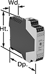
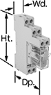
Safety Relays
Receive signals from safety monitoring relays or controllers to switch devices off and on because of a system failure. Also known as force-guided or mechanically linked contacts, the interlocking opposing contacts on these relays cannot be open or closed at the same time. To keep your system from receiving false switching signals, the interlocking opposing contact must remain open even if a contact welds closed.
IP20 rated, they have recessed terminals that prevent fingers and other objects from touching live circuits. These relays have been tested to safety standards that can help you achieve your system's PL (performance level) and SIL (safety integrity level). Choose a relay with a PL and SIL rating to meet the needs of your system. Higher ratings indicate greater safety protection. As your system becomes more complex, you generally require a higher safety protection level. Mount them to 35mm DIN rail (also known as DIN 3 Rail).
Relays that meet SIL2 are tested for applications with a probability of failure of 0.1% to 1%. They’re often used for emergency shutdowns, and fire, gas, and overpressure detection. Relays that meet SIL3 are tested for applications with a probability of failure of 0.01% to 0.1% and are used for preventing fires, explosions, or toxic releases. Relays that meet CAT 4 withstand circuit surges in electrical applications up to 600V.
When a failure is detected, relays with self-monitoring circuitry signal the controller to remove power and prevent restarting until the issue is resolved.
Relays with nondetachable contacts have auxiliary contacts that won’t separate from the relay if there is shock or vibration. Relays with mirror auxiliary contacts have contacts that are normally closed and cannot be open at the same time as a normally open main contact.
![]() For technical drawings and 3-D models, click on a part number.
For technical drawings and 3-D models, click on a part number.
| Number of Terminals | Input Voltage | Control Current, mA | Switching Current @ Voltage | Max. Switching Voltage | Ht. | Wd. | Dp. | Features | Each | |
With Screw Terminals—DIN-Rail Mount | ||||||||||
|---|---|---|---|---|---|---|---|---|---|---|
2 Circuits Controlled with 1 Off (Normally Open) and 1 On (Normally Closed)—DPST-1NO/1NC | ||||||||||
| 8 | 120V AC | 9 | 6 A @ 240 V AC | 250V AC | 3.4" | 0.9" | 3.9" | Interlocked Opposing Contacts, Recessed Terminals, LED Indicator | 00000000 | 000000 |
| 8 | 24V DC | 38 | 6 A @ 240 V AC | 250V AC | 3.4" | 0.9" | 3.9" | Interlocked Opposing Contacts, Recessed Terminals, LED Indicator | 00000000 | 00000 |
3 Circuits Controlled with 2 Off (Normally Open) and 1 On (Normally Closed)—3PST-2NO/1NC | ||||||||||
| 8 | 24V DC | 26 | 10 A @ 240 V AC | 250V AC | 3.5" | 0.7" | 2.4" | Interlocked Opposing Contacts, Recessed Terminals, LED Indicator | 00000000 | 00000 |
4 Circuits Controlled with 2 Off (Normally Open) and 2 On (Normally Closed)—4PST-2NO/2NC | ||||||||||
| 12 | 120V AC | 10 | 6 A @ 240 V AC | 250V AC | 3.4" | 0.9" | 3.9" | Interlocked Opposing Contacts, Recessed Terminals, LED Indicator | 00000000 | 000000 |
| 12 | 24V DC | 42 | 6 A @ 240 V AC | 250V AC | 3.4" | 0.9" | 3.9" | Interlocked Opposing Contacts, Recessed Terminals, LED Indicator | 00000000 | 000000 |
4 Circuits Controlled with 3 Off (Normally Open) and 1 On (Normally Closed)—4PST-3NO/1NC | ||||||||||
| 12 | 120V AC | 10 | 6 A @ 240 V AC | 250V AC | 3.4" | 0.9" | 3.9" | Interlocked Opposing Contacts, Recessed Terminals, LED Indicator | 00000000 | 000000 |
| 12 | 24V DC | 42 | 6 A @ 240 V AC | 250V AC | 3.4" | 0.9" | 3.9" | Interlocked Opposing Contacts, Recessed Terminals, LED Indicator | 00000000 | 000000 |
6 Circuits Controlled with 4 Off (Normally Open) and 2 On (Normally Closed)—6PDT-4NO/2NC | ||||||||||
| 16 | 120V AC | 10 | 6 A @ 240 V AC | 250V AC | 3.4" | 0.9" | 3.9" | Interlocked Opposing Contacts, Recessed Terminals, LED Indicator | 00000000 | 000000 |
| 16 | 24V DC | 42 | 6 A @ 240 V AC | 250V AC | 3.4" | 0.9" | 3.9" | Interlocked Opposing Contacts, Recessed Terminals, LED Indicator | 00000000 | 000000 |
6 Circuits Controlled with 5 Off (Normally Open) and 1 On (Normally Closed)—6PDT-5NO/1NC | ||||||||||
| 16 | 24V DC | 42 | 6 A @ 240 V AC | 250V AC | 3.4" | 0.9" | 3.9" | Interlocked Opposing Contacts, Recessed Terminals, LED Indicator | 00000000 | 000000 |
| Number of Terminals | Input Voltage | Control Current, mA | Switching Current @ Voltage | Max. Switching Voltage | Auxiliary Contact Switch Starting Position | Ht. | Wd. | Dp. | Features | Each | |
With Spring-Clamp Terminals—DIN-Rail Mount | |||||||||||
|---|---|---|---|---|---|---|---|---|---|---|---|
3 Circuits Controlled with 3 Off (Normally Open)—3PST-NO | |||||||||||
| 18 | 24V AC, 24V DC | 5 | 5 A @ 120 V AC | 230V AC | 1 On (Normally Closed) | 3.9" | 0.9" | 4.8" | Interlocked Opposing Contacts, Recessed Terminals, Self-Monitoring Circuitry, Nondetachable Auxiliary Contacts, Mirror Auxiliary Contacts, LED Indicator | 00000000 | 0000000 |
hp @ Switching Voltage | |||||||||||||
|---|---|---|---|---|---|---|---|---|---|---|---|---|---|
| Number of Terminals | Input Voltage | Control Current, mA | Switching Current @ Voltage | Max. Switching Voltage | Single Phase | Three Phase | Auxiliary Contact Switch Starting Position | Ht. | Wd. | Dp. | Features | Each | |
With Screw Terminals—DIN-Rail and Surface Mount | |||||||||||||
3 Circuits Controlled with 3 Off (Normally Open)—3PST-NO | |||||||||||||
| 18 | 120V AC | 2 | 7 A @ 400 V AC | 600V AC | 1/4 hp @ 120 V AC 1 hp @ 240 V AC | 2 hp @ 240 V AC 3 hp @ 480 V AC 5 hp @ 600 V AC | 2 Off (Normally Open) or 3 On (Normally Closed) | 2.7" | 1.8" | 4.6" | Interlocked Opposing Contacts, Recessed Terminals, Self-Monitoring Circuitry, Nondetachable Auxiliary Contacts, Mirror Auxiliary Contacts, Inspection Window | 0000000 | 0000000 |
| 18 | 120V AC | 2 | 9 A @ 400 V AC | 600V AC | 1/2 hp @ 120 V AC 1 1/2 hp @ 240 V AC | 3 hp @ 240 V AC 5 hp @ 480 V AC 7 1/2 hp @ 600 V AC | 2 Off (Normally Open) or 3 On (Normally Closed) | 2.7" | 1.8" | 4.6" | Interlocked Opposing Contacts, Recessed Terminals, Self-Monitoring Circuitry, Nondetachable Auxiliary Contacts, Mirror Auxiliary Contacts, Inspection Window | 0000000 | 000000 |
| 18 | 120V AC | 2 | 12 A @ 400 V AC | 600V AC | 1 hp @ 120 V AC 2 hp @ 240 V AC | 3 hp @ 240 V AC 10 hp @ 480 V AC 10 hp @ 600 V AC | 2 Off (Normally Open) or 3 On (Normally Closed) | 2.7" | 1.8" | 4.6" | Interlocked Opposing Contacts, Recessed Terminals, Self-Monitoring Circuitry, Nondetachable Auxiliary Contacts, Mirror Auxiliary Contacts, Inspection Window | 0000000 | 000000 |
| 18 | 120V AC | 5 | 18 A @ 400 V AC | 600V AC | 2 hp @ 120 V AC 3 hp @ 240 V AC | 5 hp @ 240 V AC 10 hp @ 480 V AC 15 hp @ 600 V AC | 2 Off (Normally Open) or 3 On (Normally Closed) | 3.4" | 1.8" | 5.5" | Interlocked Opposing Contacts, Recessed Terminals, Self-Monitoring Circuitry, Nondetachable Auxiliary Contacts, Mirror Auxiliary Contacts, Inspection Window | 0000000 | 000000 |
| 18 | 120V AC | 5 | 25 A @ 400 V AC | 600V AC | 2 hp @ 120 V AC 5 hp @ 240 V AC | 10 hp @ 240 V AC 15 hp @ 480 V AC 20 hp @ 600 V AC | 2 Off (Normally Open) or 3 On (Normally Closed) | 3.4" | 1.8" | 5.5" | Interlocked Opposing Contacts, Recessed Terminals, Self-Monitoring Circuitry, Nondetachable Auxiliary Contacts, Mirror Auxiliary Contacts, Inspection Window | 0000000 | 000000 |
| 18 | 24V DC | 3 | 18 A @ 400 V AC | 600V AC | 2 hp @ 120 V AC 3 hp @ 240 V AC | 5 hp @ 240 V AC 10 hp @ 480 V AC 15 hp @ 600 V AC | 2 Off (Normally Open) or 3 On (Normally Closed) | 3.4" | 1.8" | 5.5" | Interlocked Opposing Contacts, Recessed Terminals, Self-Monitoring Circuitry, Nondetachable Auxiliary Contacts, Mirror Auxiliary Contacts, Inspection Window | 0000000 | 000000 |
| 18 | 24V DC | 3 | 25 A @ 400 V AC | 600V AC | 2 hp @ 120 V AC 5 hp @ 240 V AC | 10 hp @ 240 V AC 15 hp @ 480 V AC 20 hp @ 600 V AC | 2 Off (Normally Open) or 3 On (Normally Closed) | 3.4" | 1.8" | 5.5" | Interlocked Opposing Contacts, Recessed Terminals, Self-Monitoring Circuitry, Nondetachable Auxiliary Contacts, Mirror Auxiliary Contacts, Inspection Window | 0000000 | 000000 |
| 18 | 24V DC | 12 | 7 A @ 400 V AC | 600V AC | 1/4 hp @ 120 V AC 1 hp @ 240 V AC | 2 hp @ 240 V AC 3 hp @ 480 V AC 5 hp @ 600 V AC | 2 Off (Normally Open) or 3 On (Normally Closed) | 2.7" | 1.8" | 4.6" | Interlocked Opposing Contacts, Recessed Terminals, Self-Monitoring Circuitry, Nondetachable Auxiliary Contacts, Mirror Auxiliary Contacts, Inspection Window | 0000000 | 000000 |
| 18 | 24V DC | 18 | 9 A @ 400 V AC | 600V AC | 1/2 hp @ 120 V AC 1 1/2 hp @ 240 V AC | 3 hp @ 240 V AC 5 hp @ 480 V AC 7 1/2 hp @ 600 V AC | 2 Off (Normally Open) or 3 On (Normally Closed) | 2.7" | 1.8" | 4.6" | Interlocked Opposing Contacts, Recessed Terminals, Self-Monitoring Circuitry, Nondetachable Auxiliary Contacts, Mirror Auxiliary Contacts, Inspection Window | 0000000 | 000000 |
| 18 | 24V DC | 18 | 12 A @ 400 V AC | 600V AC | 1 hp @ 120 V AC 2 hp @ 240 V AC | 3 hp @ 240 V AC 10 hp @ 480 V AC 10 hp @ 600 V AC | 2 Off (Normally Open) or 3 On (Normally Closed) | 2.7" | 1.8" | 4.6" | Interlocked Opposing Contacts, Recessed Terminals, Self-Monitoring Circuitry, Nondetachable Auxiliary Contacts, Mirror Auxiliary Contacts, Inspection Window | 0000000 | 000000 |
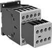
Machine-Guard Relays
The interlocked opposing contacts won't close at the same time, so these relays are suitable for safety applications such as machine guarding. The screw terminals are recessed to prevent accidental contact with live connections. Mount them on 35 mm DIN rail (also known as DIN 3 rail) or flat surfaces. These relays are built to IEC dimensional standards.
Auxiliary contact (sold separately) allows you to add a signaling device or control another relay.
| Number of Terminals | Input Voltage | Control Current, mA | Switching Current @ 600V AC | Max. Switching Voltage | Ht. | Wd. | Dp. | Each | |
4 Circuits Controlled with 2 Off (Normally Open) and 2 On (Normally Closed)—4PST-2NO/2NC | |||||||||
|---|---|---|---|---|---|---|---|---|---|
| 10 | 24V AC | 125 | 10A | 600V AC | 2.3" | 1.7" | 2.2" | 00000000 | 000000 |
| 10 | 120V AC | 25 | 10A | 600V AC | 2.3" | 1.7" | 2.2" | 00000000 | 00000 |
| 10 | 240V AC | 12.5 | 10A | 600V AC | 2.3" | 1.7" | 2.2" | 00000000 | 00000 |
4 Circuits Controlled with 3 Off (Normally Open) and 1 On (Normally Closed)—4PST-3NO/1NC | |||||||||
| 10 | 24V AC | 125 | 10A | 600V AC | 2.3" | 1.7" | 2.2" | 00000000 | 00000 |
| 10 | 120V AC | 25 | 10A | 600V AC | 2.3" | 1.7" | 2.2" | 00000000 | 00000 |
| 10 | 240V AC | 12.5 | 10A | 600V AC | 2.3" | 1.7" | 2.2" | 00000000 | 00000 |
| Number of Circuits Controlled | Switch Starting Position | Industry Designation | Mounting Location | For Relay Width | Each | |
| 2 | 1 Off (Normally Open) and 1 On (Normally Closed) | DPST-1NO/1NC | Front | 1.7" | 00000000 | 000000 |
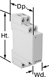
Circuit Board Safety Relays

Reduce connection errors on circuit boards that control machine guards and other safety devices. Also known as force-guided contact relays, they have contact pairs that won’t close at the same time, even if contacts stick or weld shut. These relays take up less space on a board than those with electrical wiring because their solder pin terminals mount directly through circuit board holes. Use them to control high-power components, such as fans and heaters, from a low-power circuit.
Relays with a mechanical indicator show you whether they’re switched on or off with a flag. Peek through the window on the side to quickly check the flag’s position.
Relays with surge suppression coverage protect sensitive electronics from damage and malfunction by eliminating voltage spikes. Switching off a relay can generate surges of 300 to 500 volts, but a diode within these relays suppresses these surges. An LED indicator on these relays lights up when they’re on, so you know at a glance if they’re wired correctly.
![]() For technical drawings and 3-D models, click on a part number.
For technical drawings and 3-D models, click on a part number.
| Number of Terminals | Input Voltage | Control Current, mA | Switching Current @ Voltage | Max. Switching Voltage | Mechanical Life Cycles | Ht. | Wd. | Dp. | Pin Lg. | Features | Surge Suppression Coverage | Each | |
2 Circuits Controlled with 2 Off (Normally Open) or 2 On (Normally Closed)—DPDT | |||||||||||||
|---|---|---|---|---|---|---|---|---|---|---|---|---|---|
| 8 | 12V DC | 58 | 3 A @ 240 V AC/24 V DC | 250V AC, 125V DC | 10,000,000 | 1.1" | 0.5" | 1" | 0.16" | Interlocked Opposing Contacts, Mechanical Indicator | __ | 0000000 | 000000 |
| 8 | 24V DC | 29 | 3 A @ 240 V AC/24 V DC | 250V AC, 125V DC | 10,000,000 | 1.1" | 0.5" | 1" | 0.16" | Interlocked Opposing Contacts, Mechanical Indicator | __ | 0000000 | 00000 |
| 8 | 24V DC | 29 | 8 A @ 240 V AC | 250V AC | 10,000,000 | 1.1" | 0.5" | 1" | 0.2" | Interlocked Opposing Contacts | __ | 0000000 | 00000 |
4 Circuits Controlled with 2 Off (Normally Open) and 2 On (Normally Closed)—4PST-2NO/2NC | |||||||||||||
| 10 | 12V DC | 30 | 6 A @ 240 V AC/30 V DC | 250V AC, 125V DC | 10,000,000 | 0.9" | 0.5" | 1.6" | 0.14" | Interlocked Opposing Contacts | __ | 0000000 | 00000 |
| 10 | 12V DC | 32 | 6 A @ 240 V AC/30 V DC | 250V AC, 125V DC | 10,000,000 | 0.9" | 0.5" | 1.6" | 0.14" | Interlocked Opposing Contacts, LED Indicator | Full | 0000000 | 00000 |
| 10 | 24V DC | 15 | 6 A @ 240 V AC/30 V DC | 250V AC, 125V DC | 10,000,000 | 0.9" | 0.5" | 1.6" | 0.14" | Interlocked Opposing Contacts | __ | 0000000 | 00000 |
| 10 | 24V DC | 17 | 6 A @ 240 V AC/30 V DC | 250V AC, 125V DC | 10,000,000 | 0.9" | 0.5" | 1.6" | 0.14" | Interlocked Opposing Contacts, LED Indicator | Full | 0000000 | 00000 |
4 Circuits Controlled with 3 Off (Normally Open) and 1 On (Normally Closed)—4PST-3NO/1NC | |||||||||||||
| 10 | 12V DC | 30 | 6 A @ 240 V AC/30 V DC | 250V AC, 125V DC | 10,000,000 | 0.9" | 0.5" | 1.6" | 0.14" | Interlocked Opposing Contacts | __ | 0000000 | 00000 |
| 10 | 12V DC | 32 | 6 A @ 240 V AC/30 V DC | 250V AC, 125V DC | 10,000,000 | 0.9" | 0.5" | 1.6" | 0.14" | Interlocked Opposing Contacts, LED Indicator | Full | 0000000 | 00000 |
| 10 | 24V DC | 15 | 6 A @ 240 V AC/30 V DC | 250V AC, 125V DC | 10,000,000 | 0.9" | 0.5" | 1.6" | 0.14" | Interlocked Opposing Contacts | __ | 0000000 | 00000 |
| 10 | 24V DC | 17 | 6 A @ 240 V AC/30 V DC | 250V AC, 125V DC | 10,000,000 | 0.9" | 0.5" | 1.6" | 0.14" | Interlocked Opposing Contacts, LED Indicator | Full | 0000000 | 00000 |
6 Circuits Controlled with 3 Off (Normally Open) and 3 On (Normally Closed)—6PST-3NO/3NC | |||||||||||||
| 14 | 12V DC | 41 | 6 A @ 240 V AC/30 V DC | 250V AC, 125V DC | 10,000,000 | 0.9" | 0.5" | 2" | 0.14" | Interlocked Opposing Contacts | __ | 0000000 | 00000 |
| 14 | 12V DC | 43 | 6 A @ 240 V AC/30 V DC | 250V AC, 125V DC | 10,000,000 | 0.9" | 0.5" | 2" | 0.14" | Interlocked Opposing Contacts, LED Indicator | Full | 0000000 | 00000 |
| 14 | 24V DC | 20 | 6 A @ 240 V AC/30 V DC | 250V AC, 125V DC | 10,000,000 | 0.9" | 0.5" | 2" | 0.14" | Interlocked Opposing Contacts | __ | 0000000 | 00000 |
| 14 | 24V DC | 22 | 6 A @ 240 V AC/30 V DC | 250V AC, 125V DC | 10,000,000 | 0.9" | 0.5" | 2" | 0.14" | Interlocked Opposing Contacts, LED Indicator | Full | 0000000 | 00000 |
6 Circuits Controlled with 4 Off (Normally Open) and 2 On (Normally Closed)—6PST-4NO/2NC | |||||||||||||
| 14 | 12V DC | 41 | 6 A @ 240 V AC/30 V DC | 250V AC, 125V DC | 10,000,000 | 0.9" | 0.5" | 2" | 0.14" | Interlocked Opposing Contacts | __ | 0000000 | 00000 |
| 14 | 12V DC | 43 | 6 A @ 240 V AC/30 V DC | 250V AC, 125V DC | 10,000,000 | 0.9" | 0.5" | 2" | 0.14" | Interlocked Opposing Contacts, LED Indicator | Full | 0000000 | 00000 |
| 14 | 24V DC | 20 | 6 A @ 240 V AC/30 V DC | 250V AC, 125V DC | 10,000,000 | 0.9" | 0.5" | 2" | 0.14" | Interlocked Opposing Contacts | __ | 0000000 | 00000 |
| 14 | 24V DC | 22 | 6 A @ 240 V AC/30 V DC | 250V AC, 125V DC | 10,000,000 | 0.9" | 0.5" | 2" | 0.14" | Interlocked Opposing Contacts, LED Indicator | Full | 0000000 | 00000 |
6 Circuits Controlled with 5 Off (Normally Open) and 1 On (Normally Closed)—6PST-5NO/1NC | |||||||||||||
| 14 | 12V DC | 41 | 6 A @ 240 V AC/30 V DC | 250V AC, 125V DC | 10,000,000 | 0.9" | 0.5" | 2" | 0.14" | Interlocked Opposing Contacts | __ | 0000000 | 00000 |
| 14 | 12V DC | 43 | 6 A @ 240 V AC/30 V DC | 250V AC, 125V DC | 10,000,000 | 0.9" | 0.5" | 2" | 0.14" | Interlocked Opposing Contacts, LED Indicator | Full | 0000000 | 00000 |
| 14 | 24V DC | 20 | 6 A @ 240 V AC/30 V DC | 250V AC, 125V DC | 10,000,000 | 0.9" | 0.5" | 2" | 0.14" | Interlocked Opposing Contacts | __ | 0000000 | 00000 |
| 14 | 24V DC | 22 | 6 A @ 240 V AC/30 V DC | 250V AC, 125V DC | 10,000,000 | 0.9" | 0.5" | 2" | 0.14" | Interlocked Opposing Contacts, LED Indicator | Full | 0000000 | 00000 |
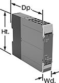
Interface Safety Relays
These relays pair the transmission reliability of an interface relay with the fail-safe operation of a safety relay. Use them to communicate signals to devices like motors or sensors. They have interlocking contacts—also known as force-guided or mechanically linked contacts—so opposing contacts won't close at the same time. This minimizes the chance of arcing, so electricity won't jump across the contacts and interfere with your relay or system. They also have an interface that isolates input and output circuits to prevent damage from voltage spikes, reduce signal interference, and amplify signal. Mount them on 35 mm DIN rail (also known as DIN 3 rail). The relays disconnect from the socket for quick replacement.
Relays with LED indicator light up when the relay is on, so you’ll know it’s wired correctly and can tell at a glance whether it’s on or off.
Relays | Replacement Relays | |||||||||||||
|---|---|---|---|---|---|---|---|---|---|---|---|---|---|---|
| Number of Terminals | Input Voltage | Control Current, mA | Switching Current @ Voltage | Max. Switching Voltage | hp @ Switching Voltage | Mechanical Life Cycles | Ht. | Wd. | Dp. | Features | Each | Each | ||
2 Circuits Controlled with 1 Off (Normally Open) and 1 On (Normally Closed)—DPST-1NO/1NC | ||||||||||||||
| 6 | 12V DC | 63 | 3 A @ 240 V AC/24 V DC | 250V AC, 125V DC | __ | 10,000,000 | 1.1" | 0.5" | 1.1" | Interlocked Opposing Contacts, LED Indicator | 0000000 | 000000 | 0000000 | 000000 |
2 Circuits Controlled with 2 Off (Normally Open) or 2 On (Normally Closed)—DPDT | ||||||||||||||
| 8 | 24V DC | 29 | 8 A @ 240 V AC | 250V AC | 1/2 hp @ 230 V AC | 10,000,000 | 3.1" | 0.6" | 2.4" | Interlocked Opposing Contacts | 0000000 | 00000 | 0000000 | 00000 |
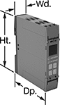
Smart Multifunction Monitoring Relays

Remotely control these relays through an app on your smartphone—they simultaneously monitor phase, voltage, and frequency. The downloadable app lets you change the tripping range, modify settings, and save programs to apply to multiple relays. Tap your smartphone or tablet to the relays to connect to them. They use NFC (near field communication), so you don’t need to manually pair them like Bluetooth devices.
You’ll often see these relays used to protect motors, generators, and other three-phase circuits from burning out or overheating. They'll switch the circuit off if they detect voltage or frequencies outside of the set range or phase loss, imbalance, or reversal. You can see that they're wired correctly and when they're actuated based on the LED indicators. Rated IP20, they have recessed terminals that keep fingers and other objects from touching live circuits. Mount them on a 35 mm DIN rail (also known as DIN 3 rail) for fast installation.
![]() For technical drawings and 3-D models, click on a part number.
For technical drawings and 3-D models, click on a part number.
Trip Voltage | Trip Frequency | |||||||||||||||
|---|---|---|---|---|---|---|---|---|---|---|---|---|---|---|---|---|
| Number of Terminals | Input Voltage | Min. | Max. | Input Frequency, Hz | Min., Hz | Max., Hz | Trip Time, sec. | Reset Type | Switching Current @ Voltage | Max. Switching Voltage | Ht. | Wd. | Dp. | Operating System Compatibility | Each | |
2 Circuits Controlled with 2 Off (Normally Open) or 2 On (Normally Closed)—DPDT | ||||||||||||||||
With Screw Terminals | ||||||||||||||||
| 12 | 208V AC, 240V AC, 300V AC, 480V AC | 208V AC | 480V AC | 50, 60 | 45 | 66 | 0.1-60 | Automatic | 8 A @ 240 V AC | 250V AC | 3.5" | 0.9" | 3.9" | Android 7.0 or Later, iOS 14.5 or Later | 0000000 | 0000000 |
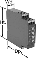
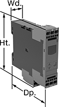
Multifunction Monitoring Relays
Monitor phase, voltage, and frequency at the same time to protect motors, generators, and other three-phase circuits from burning out or overheating. They'll switch the circuit off if they detect voltage or frequencies outside of the set range or phase loss, imbalance, or reversal. Rated IP20, they have recessed terminals that keep fingers and other objects from touching live circuits. Mount them on a 35 mm DIN (also known as DIN 3 rail) for fast installation.
These relays use IO Link, so they can be programmed, monitored, and reset remotely by connecting them to a programmable logic controller (PLC), human-machine interface (HMI), or computer. If you want to program them locally, they have a keypad.
Relays with spring-clamp terminals connect and disconnect to wire without screws. Because there’s no screw, these connections are less likely to loosen over time, even in high-vibration environments.
![]() For technical drawings and 3-D models, click on a part number.
For technical drawings and 3-D models, click on a part number.
Trip Voltage | Trip Frequency | |||||||||||||||
|---|---|---|---|---|---|---|---|---|---|---|---|---|---|---|---|---|
| Number of Terminals | Input Voltage | Min. | Max. | Input Frequency, Hz | Min., Hz | Max., Hz | Trip Time, sec. | Reset Type | Switching Current @ Voltage | Max. Switching Voltage | Adjustment Style | Ht. | Wd. | Dp. | Each | |
1 Circuit Controlled with 1 Off (Normally Open) or 1 On (Normally Closed)—SPDT | ||||||||||||||||
With Screw Terminals and IO Link | ||||||||||||||||
| 12 | 24V DC | 90V AC | 760V AC | 50, 60 | 15 | 70 | 0.1-30 | Automatic | 3 A @ 240 V AC 1 A @ 24 V DC | 400V AC 250V DC | Keypad, External Controller | 3.9" | 0.9" | 3.6" | 0000000 | 0000000 |
With Spring-Clamp Terminals and IO Link | ||||||||||||||||
| 12 | 24V DC | 90V AC | 760V AC | 50, 60 | 15 | 70 | 0.1-30 | Automatic | 3 A @ 240 V AC 1 A @ 24 V DC | 400V AC 250V DC | Keypad, External Controller | 3.9" | 0.9" | 3.6" | 0000000 | 000000 |
Current-Monitoring Relays
Protect electrical equipment from overcurrent and undercurrent damage—these relays continuously monitor current flow. When current is outside a set range, they trip and cut power to prevent overheating, fire hazards, and stalling. Rated IP20, these relays have recessed terminals that keep fingers and other objects from touching live circuits. Mount them on a 35 mm DIN rail (also known as DIN 3 rail) for fast installation.
Relays with spring-clamp terminals connect and disconnect to wire without screws. Because there’s no screw, these connections are less likely to loosen over time, even in high-vibration environments.
Relays with IO link can be programmed, monitored, and reset remotely by connecting them to a programmable logic controller (PLC), human-machine interface (HMI), or computer. If you want to program them locally, they have a keypad.
Relays with knob adjustments have knobs right on the front where you can set your trip current. You can see that they're wired correctly and when they're actuated based on the LED indicators.
![]() For technical drawings and 3-D models, click on a part number.
For technical drawings and 3-D models, click on a part number.
Trip Current | |||||||||||||||
|---|---|---|---|---|---|---|---|---|---|---|---|---|---|---|---|
| No. of Terminals | Input Voltage | Trip Current Setting | Min. | Max. | Trip Time, sec. | Reset Type | Switching Current @ Voltage | Max. Switching Voltage | Adjustment Style | Ht. | Wd. | Dp. | Display Type | Each | |
Screw Terminals | |||||||||||||||
1 Off (Normally Open) or 1 On (Normally Closed)—SPDT | |||||||||||||||
| 9 | 24V AC, 24V DC | 0.1-1A, 0.5-5A, 0.8-8A | __ | __ | 0.1-30 | Automatic, Manual | 5 A @ 240 V AC 5 A @ 30 V DC | 250V AC 30V DC | Knob | 3.5" | 0.9" | 3.9" | __ | 0000000 | 0000000 |
| 9 | 120V AC, 240V AC | 0.1-1A, 0.5-5A, 0.8-8A | __ | __ | 0.1-30 | Automatic, Manual | 5 A @ 240 V AC 5 A @ 30 V DC | 250V AC 30V DC | Knob | 3.5" | 0.9" | 3.9" | __ | 0000000 | 000000 |
Screw Terminals with IO Link | |||||||||||||||
1 Off (Normally Open) or 1 On (Normally Closed)—SPDT | |||||||||||||||
| 9 | 24V DC | __ | 0.05A | 10A | 0-999 | Automatic | 1 A @ 24 V DC 3 A @ 240 V AC | 400V AC 250V DC | External Controller, Keypad | 3.6" | 0.9" | 3.4" | LCD | 0000000 | 000000 |
Spring-Clamp Terminals with IO Link | |||||||||||||||
1 Off (Normally Open) or 1 On (Normally Closed)—SPDT | |||||||||||||||
| 9 | 24V DC | __ | 0.05A | 10A | 0-999 | Automatic | 1 A @ 24 V DC 3 A @ 240 V AC | 400V AC 250V DC | External Controller, Keypad | 3.8" | 0.9" | 3.4" | LCD | 0000000 | 000000 |
Analog-Input Proportional-Control Relays

Often used to regulate the speed of AC fans or keep a heater at a set temperature, these relays connect directly to sensors to calculate and adjust output power. This allows you to use an analog input without converting it to a digital signal to control output power. They are solid state and have no moving parts, so they require less maintenance and last longer, are quieter, and switch faster than mechanical relays. IP20 rated, they have recessed terminals that prevent fingers and other objects from touching live circuits. An integrated heat sink disperses heat to increase the relay’s current rating. The LED indicator shows input voltage loss and internal relay faults, so you can easily check that your system is operating properly.
Mount them on 35 mm DIN rail (also known as DIN 3 rail) for fast installation. They also mount to flat surfaces.
All relays have phase-angle switching to accurately control all types of loads. This mode signals at non-zero voltage, which can produce electrical noise. Choose relays with full-cycle switching for resistive loads. This mode signals at zero voltage, so electrical interference is lower than phase-angle switching.
Three-phase relays switch every cycle.
Relays with over-temperature protection stop power when it gets too hot and keeps it off until the issue is resolved. Connect an auxiliary contact (not included) to signal an alarm or status controller.
Relays with short-circuit protection stop power if there is an open circuit, short circuit, or output voltage loss until the issue is resolved. Connect an auxiliary contact (not included) to signal an alarm or status controller.
![]() For technical drawings and 3-D models, click on a part number.
For technical drawings and 3-D models, click on a part number.
Input | Output | ||||||||||||||
|---|---|---|---|---|---|---|---|---|---|---|---|---|---|---|---|
| Number of Terminals | Current | No. of | Voltage | Current | No. of | Control Current, mA | Switching Current @ Voltage | Max. Switching Voltage | Protections Provided | Ht. | Wd. | Dp. | Features | Each | |
3 Circuits Controlled with 3 Off (Normally Open)—3PST-NO | |||||||||||||||
Three Phase with Phase Angle and Full Cycle Switching Mode | |||||||||||||||
| 19 | 0-20mA | 1 | 180-660V AC | 65A | 3 | 50 | 65 A @ 600 V AC | 660V AC | Over Temperature | 4.3" | 2.84" | 5.56" | Integrated Heat Sink, LED Indicator, Recessed Terminals, Integrated Fan | 0000000 | 0000000 |
| 19 | 0-20mA | 1 | 180-660V AC | 65A | 3 | 50 | 65 A @ 600 V AC | 660V AC | Short Circuit | 4.3" | 2.84" | 5.56" | Integrated Heat Sink, LED Indicator, Recessed Terminals, Integrated Fan, Open Circuit, Configurable Alarm Outputs, Output Voltage Loss | 0000000 | 000000 |
Two-Hand Safety Switches
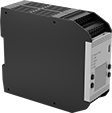
It takes two hands to activate these switches, minimizing the risk of accidental equipment start up. They have an emergency stop push-button to immediately cut power. They’re rated IP65 for protection from low-pressure washdowns.
Switches with push-button actuators require a safety relay (sold separately) for a complete system.
Switches with finger-touch actuators turn circuits on and off with a light touch, even when wearing gloves. An infrared sensor detects the lightest finger contact, and an indicator lights up to confirm when they are activated. Because they don't require you to press down a button to operate, they meet ANSI B11.TR1 standards to reduce hand, wrist, and arm fatigue. You'll need a relay or controller to complete your system—upgrade to a controller if you plan to operate additional devices beyond your switch.
Safety controller expansion modules can be added to safety controllers to increase the number of inputs.
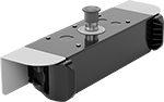
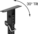
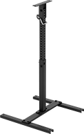
Telescoping stands can be added to switches with finger-touch actuators to mount them away from a wall. The stands telescope to adjust the height of the switch and tilt to adjust the angle of the switch.
![]() For technical drawings and 3-D models, click on a part number.
For technical drawings and 3-D models, click on a part number.

Actuator | Mounting | ||||||||||||||
|---|---|---|---|---|---|---|---|---|---|---|---|---|---|---|---|
| No. of Circuits Controlled | Switch Starting Position | Switch Action | Industry Designation | Material | Color | Switching Current @ Voltage | Ht. | Wd. | Dp. | No. of Holes | Hole Dia. | Mounting Fasteners Included | Features | Each | |
Push-Button Actuators | |||||||||||||||
| 2 | 1 Off (Normally Open) and 1 On (Normally Closed) | Springs Back (Momentary) | DPST-1NO/1NC | Plastic | Black | 8 A @ 250 V AC, 5 A @ 24 V DC | 7 5/16" | 18 1/2" | 5 7/16" | 2 | 29/64" | No | Emergency Stop Button | 00000000 | 0000000 |
Finger-Touch Actuators | |||||||||||||||
| 2 | 1 Off (Normally Open) and 1 On (Normally Closed) | Springs Back (Momentary) | DPST-1NO/1NC | Plastic | Black | 0.15 A @ 24 V DC | 3 7/16" | 18 11/16" | 5 1/2" | 4 | 21/64" | No | Emergency Stop Button, Output Indicator, Power Indicator | 00000000 | 000000 |

| Input Voltage | No. of Terminals | Switching Current @ Voltage | For DIN Rail Ht., mm | Wire Connection Type | Features | Each | |
2 Circuits Contolled with 1 Off (Normally Open) and 1 On (Normally Closed)—DPST-1NO/1NC | |||||||
|---|---|---|---|---|---|---|---|
| 24V DC | 12 | 5.5 A @ 24 V DC | 35 | Screw Terminals | Self-Monitoring Circuitry | 00000000 | 0000000 |
hp @ Switching Voltage | ||||||||||||
|---|---|---|---|---|---|---|---|---|---|---|---|---|
| Input Voltage | No. of Terminals | Switching Current @ Voltage | Max. Switching Voltage | Single Phase | Three Phase | Auxiliary Contact Switch Starting Position (No. of Contacts) | For DIN Rail Size, mm | Wire Connection Type | Features | Max. System Safety Rating | Each | |
3 Circuits Controlled with 3 Off (Normally Open) or 3 On (Normally Closed)—3PST | ||||||||||||
| 24V DC | 18 | 20 A @ 600 V AC | 600V AC | 1/2 hp @ 120 V AC 1 1/2 hp @ 240 V AC | 3 hp @ 240 V AC 5 hp @ 480 V AC 7 1/2 hp @ 600 V AC | 1 Off (Normally Open) (2) 1 On (Normally Closed) (3) | 35 | Screw-Clamp Terminals | Inspection Window, Interlocked Opposing Contacts, Mirror Contacts, Nondetachable Contacts, Recessed Terminals, Self-Monitoring Circuitry | PLe, SIL3, CAT 4, 600V | 0000000 | 0000000 |


USB Connection | Ethernet Connection | ||||||||||||||
|---|---|---|---|---|---|---|---|---|---|---|---|---|---|---|---|
| No. of Inputs | Input Voltage | Signal Output Type | Type | Standard | Gender | Type | Gender | Communication Protocol | For Max. No. of Expansion Modules | Ht. | Wd. | Dp. | Display Type | Each | |
USB Connection | |||||||||||||||
| 26 | 24V DC | PNP | Micro B | 2.0 | Female | __ | __ | __ | 8 | 4 5/16" | 1 3/4" | 5 1/16" | LCD | 00000000 | 000000000 |
USB and Ethernet Connection | |||||||||||||||
| 26 | 24V DC | PNP | Micro B | 2.0 | Female | RJ45 | Female | Ethernet/IP, Modbus TCP, Profinet | 8 | 4 5/16" | 1 3/4" | 5 1/16" | __ | 00000000 | 00000000 |

| Input Voltage | No. of Outputs | Signal Output Type | Ht. | Wd. | Dp. | Each | |
| 24V DC | 4 | PNP | 4 5/16" | 1" | 5 1/16" | 00000000 | 0000000 |
Base Mounting Holes | Head Mounting Holes | |||||||||||
|---|---|---|---|---|---|---|---|---|---|---|---|---|
| Ht. | Wd. | Dp. | Head Movement | Tilt Range of Motion | Material | No. of | Dia. | No. of | Dia. | Mounting Fasteners Included | Each | |
| 31 1/2"-48 1/2" | 24 1/16" | 24" | Tilt | 30° | Steel | 4 | 29/64" | 2 | 5/16" | Yes | 00000000 | 0000000 |

Mounting | ||||||||
|---|---|---|---|---|---|---|---|---|
| Ht. | Wd. | Dp. | Material | No. of Holes | Hole Dia. | Mounting Fasteners Included | Each | |
| 5 15/16" | 10 1/4" | 3/8" | Steel | 4 | 3/8" | Yes | 00000000 | 000000 |

Wire Leads | |||||||||||
|---|---|---|---|---|---|---|---|---|---|---|---|
| Input Voltage | Signal Output Type | Ht. | Wd. | Dp. | Thread Size | Cable Lg., ft. | No. of | Lg., ft. | Features | Each | |
| 10V DC-30V DC | PNP | 2 5/16" | 2 3/8" | 1 11/16" | M30 × 1.5 mm | 1 | 5 | 1 | Output Indicator, Power Indicator | 00000000 | 0000000 |
Dual-Operator Safety Switches

To prevent accidents, these switches won’t let your machine start running unless two people in different locations coordinate control. This is useful for large operations where it would be difficult to hear or see someone call for power to be cut. They come with two foot switches that communicate wirelessly—both need to be pressed at the same time for your machine to run. For example, if used with a machine that pulls wire up a building through conduit, this means that two people dozens of floors apart can each stop the machine by releasing their foot. As an extra precaution, give the included pendant switches to people walking around your operation. If they see a problem, the pendant switches shut power off with a push of a button, even if the foot switches are pressed.
The foot switches work up to 3.7 miles away from each other if there’s a clear line of sight between the two. If there are walls or other obstacles, they work up to 1,500 ft. away from each other. Plug your equipment into the receiver foot switch before plugging the switch into an outlet—no wiring is required.
| No. of Circuits Controlled | Switch Starting Position | Switch Action | Industry Designation | Switching Current @ Voltage | Max. Transmission Distance, mi | Ht. | Wd. | Dp. | Environmental Rating | Includes | Each | |
Aluminum Housing with Amperage Draw Gauge and LED Status Indicator | ||||||||||||
|---|---|---|---|---|---|---|---|---|---|---|---|---|
NEMA 5-20 Plug × NEMA 5-20 Socket | ||||||||||||
| 1 | 1 Off (Normally Open) | Springs Back (Momentary) | SPST-NO | 20 A @ 120 V AC | 3.7 | 4 1/4" | 6 1/4" | 12 1/4" | IP55 | Receiver Foot Switch, Transmitter Foot Switch, Two Wireless Pendant Switches, Carrying Case, NEMA 5-15 Plug Adapter, Turn-Lock Plug Adapter, Two Battery Chargers | 0000000 | 000000000 |