


About Shaft Couplings
More
High-Torque Flexible Shaft Couplings
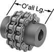
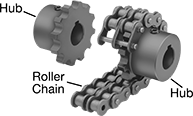
With a rugged roller-chain design, these couplings provide excellent torque and angular misalignment capacities. Lubrication is required. Fasten to your shaft by tightening the set screws, which bite into the shaft to hold it.
A complete coupling consists of two hubs and one roller chain (each component sold separately). Complete couplings meet ANSI B29.23M-1995.
Optional covers retain grease lubrication and provide protection from abrasion and corrosion.
![]() For technical drawings and 3-D models, click on a part number.
For technical drawings and 3-D models, click on a part number.
Steel Roller Chain | ||||||||||||||||
|---|---|---|---|---|---|---|---|---|---|---|---|---|---|---|---|---|
Steel Hubs | Misalignment Capability | Roller Chain | Orange Nylon Plastic Covers | |||||||||||||
| O'all Lg. | OD | OD with Cover | For Motion Type | For Shaft Dia. | Each | Max. Speed, rpm | Max. Torque, in.-lbs. | Parallel | Angular | No. | Standard | Each | Each | |||
| 2 9/16" | 2 13/32" | 4" | Continuous | 0000000 | 000000 | 5,000 | 1,355 | 0.012" | 2° | 40-2 | ANSI | 0000000 | 000000 | 0000000 | 0000000 | |
| 2 9/16" | 3 3/64" | 4" | Continuous | 0000000 | 00000 | 5,000 | 2,410 | 0.012" | 2° | 40-2 | ANSI | 0000000 | 00000 | 0000000 | 000000 | |
| 2 29/32" | 3 25/32" | 5 1/8" | Continuous | 0000000 | 00000 | 4,000 | 4,610 | 0.012" | 2° | 50-2 | ANSI | 0000000 | 00000 | 0000000 | 000000 | |
| 3 29/64" | 5" | 6 3/8" | Continuous | 0000000 | 00000 | 3,000 | 10,900 | 0.012" | 1.5° | 60-2 | ANSI | 0000000 | 00000 | 0000000 | 000000 | |
High-Torque Friction Torque Limiters


With rugged roller chains, these torque limiters handle more torque than other torque limiters. They have a disc that creates friction to prevent torque overload, control tension, and brake. If there’s too much torque, they’ll slip and only transmit the set torque. For example, they could be used in a machine that tightens a bottle cap to a certain torque without overtightening and breaking the bottle. Because they rely on friction, exposing them to moisture, oil, or lubricants can affect their performance. You can adjust the torque by rotating the hex nut on the hub.
They act as a flexible shaft coupling, so they reduce vibration and protect components from wear by compensating for angular and parallel misalignment. Fasten them to your shafts by tightening the set screws, which bite into each shaft to hold it.
Single-spring torque limiters let you make finer torque adjustments than double-spring torque limiters but can only withstand half as much torque.
Double-spring torque limiters handle twice as much torque as single-spring torque limiters but are not the best for making precise adjustments at low torques.
![]() For technical drawings and 3-D models, click on a part number.
For technical drawings and 3-D models, click on a part number.
Torque, ft.-lbs. | Misalignment Capability | Roller Chain | ||||||||||||
|---|---|---|---|---|---|---|---|---|---|---|---|---|---|---|
| For Shaft Dia. | For Shaft Type | Min. | Max. | Max. Speed, rpm | Parallel | Angular | OD | Overall Lg. | Keyway Wd. × Keyway Dp. | Drive Direction | Standard | Trade Size | Each | |
Single Spring | ||||||||||||||
| 1/2" × 1/2" | Round × Round | 0 | 25 | 1,800 | 0.01" | 3° | 2 3/4" | 2 1/4" | __ | Clockwise and Counterclockwise | ANSI | 35-2 | 00000000 | 0000000 |
| 1/2" × 5/8" | Round × Keyed | 0 | 25 | 1,800 | 0.01" | 3° | 2 3/4" | 2 1/4" | 3/16" × 3/32" | Clockwise and Counterclockwise | ANSI | 35-2 | 00000000 | 000000 |
| 1/2" × 3/4" | Round × Keyed | 0 | 25 | 1,800 | 0.01" | 3° | 2 3/4" | 2 1/4" | 3/16" × 3/32" | Clockwise and Counterclockwise | ANSI | 35-2 | 00000000 | 000000 |
| 5/8" × 5/8" | Keyed × Keyed | 0 | 25 | 1,800 | 0.01" | 3° | 2 3/4" | 2 1/4" | 3/16" × 3/32" 3/16" × 3/32" | Clockwise and Counterclockwise | ANSI | 35-2 | 00000000 | 000000 |
| 5/8" × 3/4" | Keyed × Keyed | 0 | 25 | 1,800 | 0.01" | 3° | 2 3/4" | 2 1/4" | 3/16" × 3/32" 3/16" × 3/32" | Clockwise and Counterclockwise | ANSI | 35-2 | 00000000 | 000000 |
| 3/4" × 3/4" | Keyed × Keyed | 0 | 25 | 1,800 | 0.01" | 3° | 2 3/4" | 2 1/4" | 3/16" × 3/32" 3/16" × 3/32" | Clockwise and Counterclockwise | ANSI | 35-2 | 00000000 | 000000 |
| 1" × 1" | Keyed × Keyed | 0 | 75 | 1,800 | 0.01" | 3° | 3 11/16" | 2 13/16" | 1/4" × 1/8" 1/4" × 1/8" | Clockwise and Counterclockwise | ANSI | 40-2 | 00000000 | 000000 |
| 12mm × 12mm | Keyed × Keyed | 0 | 25 | 1,800 | 0.01" | 3° | 2 3/4" | 2 1/4" | 4mm × 2mm 4mm × 2mm | Clockwise and Counterclockwise | ANSI | 35-2 | 00000000 | 000000 |
| 12mm × 15mm | Keyed × Keyed | 0 | 25 | 1,800 | 0.01" | 3° | 2 3/4" | 2 1/4" | 4mm × 2mm 5mm × 2.5mm | Clockwise and Counterclockwise | ANSI | 35-2 | 00000000 | 000000 |
| 15mm × 15mm | Keyed × Keyed | 0 | 25 | 1,800 | 0.01" | 3° | 2 3/4" | 2 1/4" | 5mm × 2.5mm 5mm × 2.5mm | Clockwise and Counterclockwise | ANSI | 35-2 | 00000000 | 000000 |
| 15mm × 20mm | Keyed × Keyed | 0 | 75 | 1,800 | 0.01" | 3° | 3 11/16" | 2 13/16" | 5mm × 2.5mm 6mm × 3mm | Clockwise and Counterclockwise | ANSI | 40-2 | 00000000 | 000000 |
| 20mm × 20mm | Keyed × Keyed | 0 | 75 | 1,800 | 0.01" | 3° | 3 11/16" | 2 13/16" | 6mm × 3mm 6mm × 3mm | Clockwise and Counterclockwise | ANSI | 40-2 | 00000000 | 000000 |
| 20mm × 25mm | Keyed × Keyed | 0 | 75 | 1,800 | 0.01" | 3° | 3 11/16" | 2 13/16" | 6mm × 3mm 8mm × 4mm | Clockwise and Counterclockwise | ANSI | 40-2 | 00000000 | 000000 |
| 25mm × 25mm | Keyed × Keyed | 0 | 75 | 1,800 | 0.01" | 3° | 3 11/16" | 2 13/16" | 8mm × 4mm 8mm × 4mm | Clockwise and Counterclockwise | ANSI | 40-2 | 00000000 | 000000 |
Double Spring | ||||||||||||||
| 1/2" × 1/2" | Round × Round | 0 | 50 | 1,800 | 0.01" | 3° | 2 3/4" | 2 1/4" | __ | Clockwise and Counterclockwise | ANSI | 35-2 | 00000000 | 000000 |
| 1/2" × 5/8" | Round × Keyed | 0 | 50 | 1,800 | 0.01" | 3° | 2 3/4" | 2 1/4" | 3/16" × 3/32" | Clockwise and Counterclockwise | ANSI | 35-2 | 00000000 | 000000 |
| 1/2" × 3/4" | Round × Keyed | 0 | 50 | 1,800 | 0.01" | 3° | 2 3/4" | 2 1/4" | 3/16" × 3/32" | Clockwise and Counterclockwise | ANSI | 35-2 | 00000000 | 000000 |
| 5/8" × 5/8" | Keyed × Keyed | 0 | 50 | 1,800 | 0.01" | 3° | 2 3/4" | 2 1/4" | 3/16" × 3/32" 3/16" × 3/32" | Clockwise and Counterclockwise | ANSI | 35-2 | 00000000 | 000000 |
| 5/8" × 3/4" | Keyed × Keyed | 0 | 50 | 1,800 | 0.01" | 3° | 2 3/4" | 2 1/4" | 3/16" × 3/32" 3/16" × 3/32" | Clockwise and Counterclockwise | ANSI | 35-2 | 00000000 | 000000 |
| 3/4" × 3/4" | Keyed × Keyed | 0 | 50 | 1,800 | 0.01" | 3° | 2 3/4" | 2 1/4" | 3/16" × 3/32" 3/16" × 3/32" | Clockwise and Counterclockwise | ANSI | 35-2 | 00000000 | 000000 |
| 1" × 1" | Keyed × Keyed | 0 | 150 | 1,800 | 0.01" | 3° | 3 11/16" | 2 13/16" | 1/4" × 1/8" 1/4" × 1/8" | Clockwise and Counterclockwise | ANSI | 40-2 | 00000000 | 000000 |
| 12mm × 12mm | Keyed × Keyed | 0 | 50 | 1,800 | 0.01" | 3° | 2 3/4" | 2 1/4" | 4mm × 2mm 4mm × 2mm | Clockwise and Counterclockwise | ANSI | 35-2 | 00000000 | 000000 |
| 12mm × 15mm | Keyed × Keyed | 0 | 50 | 1,800 | 0.01" | 3° | 2 3/4" | 2 1/4" | 4mm × 2mm 5mm × 2.5mm | Clockwise and Counterclockwise | ANSI | 35-2 | 00000000 | 000000 |
| 15mm × 15mm | Keyed × Keyed | 0 | 50 | 1,800 | 0.01" | 3° | 2 3/4" | 2 1/4" | 5mm × 2.5mm 5mm × 2.5mm | Clockwise and Counterclockwise | ANSI | 35-2 | 00000000 | 000000 |
| 15mm × 20mm | Keyed × Keyed | 0 | 150 | 1,800 | 0.01" | 3° | 3 11/16" | 2 13/16" | 5mm × 2.5mm 6mm × 3mm | Clockwise and Counterclockwise | ANSI | 40-2 | 00000000 | 000000 |
| 20mm × 20mm | Keyed × Keyed | 0 | 150 | 1,800 | 0.01" | 3° | 3 11/16" | 2 13/16" | 6mm × 3mm 6mm × 3mm | Clockwise and Counterclockwise | ANSI | 40-2 | 00000000 | 000000 |
| 20mm × 25mm | Keyed × Keyed | 0 | 150 | 1,800 | 0.01" | 3° | 3 11/16" | 2 13/16" | 6mm × 3mm 8mm × 4mm | Clockwise and Counterclockwise | ANSI | 40-2 | 00000000 | 000000 |
| 25mm × 25mm | Keyed × Keyed | 0 | 150 | 1,800 | 0.01" | 3° | 3 11/16" | 2 13/16" | 8mm × 4mm 8mm × 4mm | Clockwise and Counterclockwise | ANSI | 40-2 | 00000000 | 000000 |