


DIN-Rail Mount Interface Relays

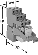
Isolate input and output circuits to prevent damage from voltage spikes, reduce signal interference, and amplify signal. These relays interface between your controller and components—they receive a signal from the controller to switch power on or off to the components. All have an LED indicator that shows you if your switch is actuated, so you know it’s connected and wired correctly. Use them to communicate signals to devices like motors or sensors. Mount them on 35 mm DIN rail (also known as DIN 3 rail).
Relays with spring-clamp terminals connect and disconnect to wires without needing to turn screws. Because there is no screw, these connections have less risk of loosening over time than screw terminals, even when there is vibration.
Relays with PLC output protection prevent voltage spikes created by the relay from damaging the output channel on your programmable logic controller (PLC).
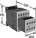
![]() For technical drawings and 3-D models, click on a part number.
For technical drawings and 3-D models, click on a part number.
Relays with Relay Sockets | Replacement Relays | |||||||||||
|---|---|---|---|---|---|---|---|---|---|---|---|---|
| Number of Terminals | Input Voltage | Control Current, mA | Switching Current @ 240V AC | hp @ Switching Voltage | Ht. | Wd. | Dp. | Features | Each | Each | ||
4 Circuits Controlled with 4 Off (Normally Open) or 4 On (Normally Closed)—4PDT | ||||||||||||
With Screw Terminals | ||||||||||||
| 14 | 24V AC | 53 | 7A | 1/8 hp @ 120 V AC | 3.1" | 1.1" | 3.3" | LED Indicator, PLC Output Protection | 00000000 | 000000 | 00000000 | 000000 |
| 14 | 120V AC | 12 | 7A | 1/8 hp @ 120 V AC | 3.1" | 1.1" | 3.3" | LED Indicator, PLC Output Protection | 00000000 | 00000 | 00000000 | 00000 |
| 14 | 12V DC | 86 | 7A | 1/8 hp @ 120 V AC | 3.1" | 1.1" | 3.3" | LED Indicator, PLC Output Protection | 00000000 | 00000 | 00000000 | 00000 |
| 14 | 24V DC | 40 | 7A | 1/8 hp @ 120 V AC | 3.1" | 1.1" | 3.3" | LED Indicator, PLC Output Protection | 00000000 | 00000 | 00000000 | 00000 |
With Spring-Clamp Terminals | ||||||||||||
| 14 | 24V AC | 53 | 7A | 1/8 hp @ 120 V AC | 3.9" | 1.2" | 3.3" | LED Indicator, PLC Output Protection | 00000000 | 00000 | 00000000 | 00000 |
| 14 | 12V DC | 86 | 7A | 1/8 hp @ 120 V AC | 3.9" | 1.2" | 3.3" | LED Indicator, PLC Output Protection | 00000000 | 00000 | 00000000 | 00000 |
| 14 | 24V DC | 40 | 7A | 1/8 hp @ 120 V AC | 3.9" | 1.2" | 3.3" | LED Indicator, PLC Output Protection | 00000000 | 00000 | 00000000 | 00000 |
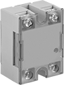
Solid State Screw Terminal Relays
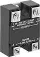
Covered Terminals
and LED Indicator
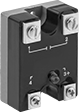

With no moving parts, these solid-state relays are fast switching and require less maintenance, last longer, and are quieter than mechanical switches.
Relays with high-starting-current protection are designed with integrated circuits that prevent damage from the large burst of electricity when a device, such as a motor or pump, turns on.
Relays with LED indicator let you quickly spot whether a relay is on or off.
Heat sinks disperse heat to increase the relay’s current rating. Mount them to 35 mm DIN rail (also known as DIN 3 rail) for fast installation. They also mount to flat surfaces. Before mounting one-circuit relays, silicone compound or a thermal pad should be placed between the heat sink and relay. Silicone compound is sold separately for heat sinks that do not include it but require it. Two-circuit relays don’t require silicone for mounting.
Relays | ||||||||||||||
|---|---|---|---|---|---|---|---|---|---|---|---|---|---|---|
Switching Current | Heat Sinks | Silicone Compounds | ||||||||||||
| Number of Terminals | Input Voltage | Without Heat Sink | With Heat Sink | Switching Voltage | Max. Switching Voltage | Ht. | Wd. | Dp. | Each | Each | Each | |||
1 Circuit Controlled with 1 Off (Normally Open)—SPST-NO | ||||||||||||||
Relays with High-Starting-Current Protection | ||||||||||||||
| 4 | 85V AC, 120V AC, 240V AC, 280V AC | 7A | 25A | 120V AC | 140V AC | 2.3" | 1.8" | 1" | 0000000 | 000000 | 0000000 | 0000000 | 000000 | 00 |
| 4 | 85V AC, 120V AC, 240V AC, 280V AC | 7A | 25A | 240V AC | 280V AC | 2.3" | 1.8" | 1" | 0000000 | 00000 | 0000000 | 000000 | 000000 | 00 |
| 4 | 3V DC, 6V DC, 12V DC, 24V DC, 30V DC | 7A | 25A | 380V AC | 420V AC | 2.3" | 1.8" | 1" | 00000000 | 00000 | 0000000 | 000000 | 000000 | 00 |
| 4 | 3V DC, 6V DC, 12V DC, 24V DC, 30V DC | 7A | 25A | 120V AC | 140V AC | 2.3" | 1.8" | 1" | 0000000 | 00000 | 0000000 | 000000 | 000000 | 00 |
| 4 | 3V DC, 6V DC, 12V DC, 24V DC, 30V DC | 7A | 25A | 240V AC | 280V AC | 2.3" | 1.8" | 1" | 0000000 | 00000 | 0000000 | 000000 | 000000 | 00 |
Relays with High-Starting-Current Protection and Covered Terminals and LED Indicator | ||||||||||||||
| 4 | 120V AC, 240V AC | 7A | 75A | 240V AC | 240V AC | 2.3" | 1.8" | 1.1" | 0000000 | 000000 | 0000000 | 000000 | 00000000 | 000000 |
| 4 | 120V AC, 240V AC | 7A | 90A | 240V AC | 240V AC | 2.3" | 1.8" | 1.1" | 0000000 | 000000 | 0000000 | 000000 | 00000000 | 00000 |
Relays with High-Starting-Current Protection and LED Indicator | ||||||||||||||
| 4 | 3V DC, 6V DC, 12V DC, 24V DC, 30V DC | 7A | 25A | 240V AC | 280V AC | 2.3" | 1.8" | 1" | 0000000 | 00000 | 0000000 | 000000 | 000000 | 00 |
Safety Relays
Receive signals from safety monitoring relays or controllers to switch devices off and on because of a system failure. Also known as force-guided or mechanically linked contacts, the interlocking opposing contacts on these relays cannot be open or closed at the same time. To keep your system from receiving false switching signals, the interlocking opposing contact must remain open even if a contact welds closed.
IP20 rated, they have recessed terminals that prevent fingers and other objects from touching live circuits. These relays have been tested to safety standards that can help you achieve your system's PL (performance level) and SIL (safety integrity level). Choose a relay with a PL and SIL rating to meet the needs of your system. Higher ratings indicate greater safety protection. As your system becomes more complex, you generally require a higher safety protection level. Mount them to 35mm DIN rail (also known as DIN 3 Rail).
Relays that meet SIL3 are tested for applications with a probability of failure of 0.01% to 0.1% and are used for preventing fires, explosions, or toxic releases. Relays that meet CAT 4 withstand circuit surges in electrical applications up to 600V.
When a failure is detected, relays with self-monitoring circuitry signal the controller to remove power and prevent restarting until the issue is resolved.
Relays with nondetachable contacts have auxiliary contacts that won’t separate from the relay if there is shock or vibration. Relays with mirror auxiliary contacts have contacts that are normally closed and cannot be open at the same time as a normally open main contact.
![]() For technical drawings and 3-D models, click on a part number.
For technical drawings and 3-D models, click on a part number.
hp @ Switching Voltage | |||||||||||||
|---|---|---|---|---|---|---|---|---|---|---|---|---|---|
| Number of Terminals | Input Voltage | Control Current, mA | Switching Current @ Voltage | Max. Switching Voltage | Single Phase | Three Phase | Auxiliary Contact Switch Starting Position | Ht. | Wd. | Dp. | Features | Each | |
With Screw Terminals—DIN-Rail and Surface Mount | |||||||||||||
3 Circuits Controlled with 3 Off (Normally Open)—3PST-NO | |||||||||||||
| 18 | 120V AC | 2 | 7 A @ 400 V AC | 600V AC | 1/4 hp @ 120 V AC 1 hp @ 240 V AC | 2 hp @ 240 V AC 3 hp @ 480 V AC 5 hp @ 600 V AC | 2 Off (Normally Open) or 3 On (Normally Closed) | 2.7" | 1.8" | 4.6" | Interlocked Opposing Contacts, Recessed Terminals, Self-Monitoring Circuitry, Nondetachable Auxiliary Contacts, Mirror Auxiliary Contacts, Inspection Window | 0000000 | 0000000 |
| 18 | 24V DC | 12 | 7 A @ 400 V AC | 600V AC | 1/4 hp @ 120 V AC 1 hp @ 240 V AC | 2 hp @ 240 V AC 3 hp @ 480 V AC 5 hp @ 600 V AC | 2 Off (Normally Open) or 3 On (Normally Closed) | 2.7" | 1.8" | 4.6" | Interlocked Opposing Contacts, Recessed Terminals, Self-Monitoring Circuitry, Nondetachable Auxiliary Contacts, Mirror Auxiliary Contacts, Inspection Window | 0000000 | 000000 |