


About Timer Relays
More
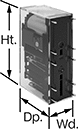
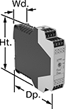
DIN-Rail Mount Interface Relays
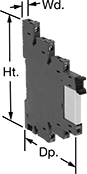


Isolate input and output circuits to prevent damage from voltage spikes, reduce signal interference, and amplify signal. These relays interface between your controller and components—they receive a signal from the controller to switch power on or off to the components. All have an LED indicator that shows you if your switch is actuated, so you know it’s connected and wired correctly. Use them to communicate signals to devices like motors or sensors. Mount them on 35 mm DIN rail (also known as DIN 3 rail).
Relays with spring-clamp terminals connect and disconnect to wires without needing to turn screws. Because there is no screw, these connections have less risk of loosening over time than screw terminals, even when there is vibration.
Relays with a fuse holder slot give you the option for additional overload protection. If the current exceeds the fuse’s rating, the fuse will blow and break the circuit. This prevents the relay from overheating, breaking, or causing a fire. The fuse holder is sold separately. You can use these relays without the fuse holder as a standard interface relay.
Relays with Relay Sockets | Replacement Relays | Fuse Holders | |||||||||||
|---|---|---|---|---|---|---|---|---|---|---|---|---|---|
| Number of Terminals | Input Voltage | Control Current, mA | Switching Current @ 240V AC | Ht. | Wd. | Dp. | Features | Each | Each | Each | |||
1 Circuit Controlled with 1 Off (Normally Open) or 1 On (Normally Closed)—SPDT | |||||||||||||
With Screw Terminals | |||||||||||||
| 5 | 240V AC | 3 | 6A | 3.5" | 0.2" | 3" | LED Indicator | 0000000 | 000000 | 0000000 | 00000 | 000000 | 00 |
| 5 | 12V AC, 12V DC | 16 | 6A | 3.5" | 0.2" | 3" | LED Indicator | 0000000 | 00000 | 0000000 | 0000 | 000000 | 00 |
| 5 | 24V AC, 24V DC | 11 | 6A | 3.5" | 0.2" | 3" | LED Indicator | 0000000 | 00000 | 0000000 | 0000 | 000000 | 00 |
| 5 | 24V AC, 24V DC | 11 | 6A | 3.7" | 0.2" | 3.5" | Fuse Holder Slot, LED Indicator | 00000000 | 00000 | 0000000 | 0000 | 00000000 | 00000 |
| 5 | 24V AC, 48V AC, 120V AC, 240V AC, 24V DC, 48V DC, 60V DC, 240V DC | 19 | 6A | 3.7" | 0.2" | 3.5" | Fuse Holder Slot, LED Indicator | 00000000 | 00000 | 0000000 | 0000 | 00000000 | 0000 |
| 5 | 120V AC, 120V DC | 5 | 6A | 3.5" | 0.2" | 3" | LED Indicator | 0000000 | 00000 | 0000000 | 0000 | 000000 | 00 |
| 5 | 120V AC, 120V DC | 5 | 6A | 3.7" | 0.2" | 3.5" | Fuse Holder Slot, LED Indicator | 00000000 | 00000 | 0000000 | 0000 | 00000000 | 0000 |
With Spring-Clamp Terminals | |||||||||||||
| 5 | 12V AC, 12V DC | 16 | 6A | 3.7" | 0.2" | 3" | LED Indicator | 0000000 | 00000 | 0000000 | 0000 | 000000 | 00 |
| 5 | 24V AC, 24V DC | 11 | 6A | 3.7" | 0.2" | 3" | LED Indicator | 0000000 | 00000 | 0000000 | 0000 | 000000 | 00 |
| 5 | 24V AC, 24V DC | 11 | 6A | 3.7" | 0.2" | 3.5" | Fuse Holder Slot, LED Indicator | 00000000 | 00000 | 0000000 | 0000 | 00000000 | 0000 |
| 5 | 24V AC, 48V AC, 120V AC, 240V AC, 24V DC, 48V DC, 60V DC, 240V DC | 19 | 6A | 3.7" | 0.2" | 3.5" | Fuse Holder Slot, LED Indicator | 00000000 | 00000 | 0000000 | 0000 | 00000000 | 0000 |
| 5 | 120V AC, 120V DC | 5 | 6A | 3.7" | 0.2" | 3" | LED Indicator | 0000000 | 00000 | 0000000 | 0000 | 000000 | 00 |
| 5 | 120V AC, 120V DC | 5 | 6A | 3.7" | 0.2" | 3.5" | Fuse Holder Slot, LED Indicator | 00000000 | 00000 | 0000000 | 0000 | 00000000 | 0000 |
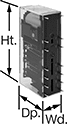
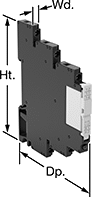
DIN-Rail Mount Solid State Interface Relays
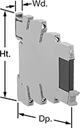
With no moving parts, these solid state relays last longer, switch faster, and are quieter than mechanical relays. They interface between your controller and components to isolate input and output circuits, which protects components from voltage spikes, amplifies the relay’s signal, and reduces interference for reliable transmission. The relay’s LED indicator shines when it’s powered on, so you know at a glance which relays are wired correctly and what the switching position is. These relays are often used for switching small motors and sensors. Rated IP20, they prevent fingers and other objects from touching live circuits.
Mount them on 35 mm DIN rail (also known as DIN 3 rail) with the included socket. Relays disconnect from the socket for easy replacement.
Relays with spring-clamp terminals connect and disconnect to wires without needing to turn screws. With no screws to shake loose with vibration, these terminals hold tight over time.
![]() For technical drawings and 3-D models, click on a part number.
For technical drawings and 3-D models, click on a part number.
Relays with Relay Socket and Retaining Clip | Replacement Relays | ||||||||||
|---|---|---|---|---|---|---|---|---|---|---|---|
| Number of Terminals | Input Voltage | Control Current, mA | Switching Current @ Voltage | Max. Switching Voltage | Ht. | Wd. | Dp. | Each | Each | ||
1 Circuit Controlled with 1 Off (Normally Open)—SPST-NO | |||||||||||
With Screw Terminals | |||||||||||
| 4 | 120V AC, 120V DC | 5.5 | 6 A @ 24 V DC | 33V DC | 3.5" | 0.2" | 3" | 0000000 | 000000 | 0000000 | 000000 |
With Spring-Clamp Terminals | |||||||||||
| 4 | 120V AC, 120V DC | 5.5 | 6 A @ 24 V DC | 33V DC | 3.7" | 0.2" | 3" | 00000000 | 00000 | 0000000 | 00000 |
| 4 | 24V DC | 10.5 | 6 A @ 24 V DC | 33V DC | 3.7" | 0.2" | 3" | 00000000 | 00000 | 0000000 | 00000 |
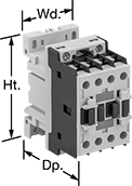
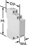
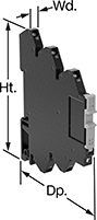
DIN-Rail Mount Touch-Safe Screw Terminal Relays
Quickly and safely mount these relays on 35 mm DIN rail (also known as DIN 3). IP20 rated, they have recessed terminals that prevent fingers and other objects from touching live circuits.
Relays that control 3 and 4 circuits are built to IEC dimensional standards and are often called IEC contactors. Auxiliary contacts (sold separately) allow you to add a signaling device or control another relay. You can add one auxiliary contact to all of these relays. For relays with 12 terminals, you can add two side-mount auxiliary contacts.
Use replacement coils to swap out a broken coil or change the input voltage of a relay. They are only compatible with relays that have 12 terminals. The full load current of the relay must match the full load current range of the coil.
![]() For technical drawings and 3-D models, click on a part number.
For technical drawings and 3-D models, click on a part number.
Control | hp @ Switching Voltage | ||||||||||
|---|---|---|---|---|---|---|---|---|---|---|---|
| Number of Terminals | Input Voltage | Power | Switching Current @ Voltage (Load Type) | Max. Switching Voltage | Single Phase | Three Phase | Ht. | Wd. | Dp. | Each | |
3 Circuits Controlled with 3 Off (Normally Open)—3PST-NO | |||||||||||
With 1 Auxiliary Contact—1 Off (Normally Open) | |||||||||||
| 10 | 24V AC | 4VA | 6 A @ 600 V AC (Full Load) 20 A @ 600 V AC (Resistive Load) | 600 V AC | 1 1/2 hp @ 240 V AC 1/2 hp @ 120 V AC | 3 hp @ 240 V AC 5 hp @ 480 V AC 5 hp @ 600 V AC | 2.3" | 1.7" | 2.2" | 000000000 | 000000 |
| 10 | 120V AC | 4VA | 6 A @ 600 V AC (Full Load) 20 A @ 600 V AC (Resistive Load) | 600 V AC | 1 1/2 hp @ 240 V AC 1/2 hp @ 120 V AC | 3 hp @ 240 V AC 5 hp @ 480 V AC 5 hp @ 600 V AC | 2.3" | 1.7" | 2.2" | 000000000 | 00000 |
| 10 | 240V AC | 4VA | 6 A @ 600 V AC (Full Load) 20 A @ 600 V AC (Resistive Load) | 600 V AC | 1 1/2 hp @ 240 V AC 1/2 hp @ 120 V AC | 3 hp @ 240 V AC 5 hp @ 480 V AC 5 hp @ 600 V AC | 2.3" | 1.7" | 2.2" | 000000000 | 00000 |
| 10 | 24V DC | 3.2W | 6 A @ 600 V AC (Full Load) 20 A @ 600 V AC (Resistive Load) | 600 V AC | 1 1/2 hp @ 240 V AC 1/2 hp @ 120 V AC | 3 hp @ 240 V AC 5 hp @ 480 V AC 5 hp @ 600 V AC | 2.3" | 1.7" | 2.2" | 00000000 | 00000 |
With 1 Auxiliary Contact—1 On (Normally Closed) | |||||||||||
| 10 | 24V AC | 4VA | 6 A @ 600 V AC (Full Load) 20 A @ 600 V AC (Resistive Load) | 600 V AC | 1 1/2 hp @ 240 V AC 1/2 hp @ 120 V AC | 3 hp @ 240 V AC 5 hp @ 480 V AC 5 hp @ 600 V AC | 2.3" | 1.7" | 2.2" | 000000000 | 00000 |
| 10 | 120V AC | 4VA | 6 A @ 600 V AC (Full Load) 20 A @ 600 V AC (Resistive Load) | 600 V AC | 1 1/2 hp @ 240 V AC 1/2 hp @ 120 V AC | 3 hp @ 240 V AC 5 hp @ 480 V AC 5 hp @ 600 V AC | 2.3" | 1.7" | 2.2" | 000000000 | 00000 |
| 10 | 240V AC | 4VA | 6 A @ 600 V AC (Full Load) 20 A @ 600 V AC (Resistive Load) | 600 V AC | 1 1/2 hp @ 240 V AC 1/2 hp @ 120 V AC | 3 hp @ 240 V AC 5 hp @ 480 V AC 5 hp @ 600 V AC | 2.3" | 1.7" | 2.2" | 000000000 | 00000 |
| 10 | 24V DC | 3.2W | 6 A @ 600 V AC (Full Load) 20 A @ 600 V AC (Resistive Load) | 600 V AC | 1 1/2 hp @ 240 V AC 1/2 hp @ 120 V AC | 3 hp @ 240 V AC 5 hp @ 480 V AC 5 hp @ 600 V AC | 2.3" | 1.7" | 2.2" | 00000000 | 00000 |

| Number of Circuits Controlled | For Relay Width | Switch Starting Position | Industry Designation | Mounting Location | Each | |
| 2 | 1.7" | 1 Off (Normally Open) and 1 On (Normally Closed) | DPST-1NO/1NC | Front | 00000000 | 000000 |
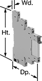
Circuit Board Relays


Smaller than relays with electrical wiring, these relays fit in compact devices. Mount them through holes on circuit boards with their solder pin terminals. Use them to control heaters, fans, and other high-power components from a low-power circuit.
Solid state relays have no moving parts, so they require less maintenance and last longer, switch faster, and are quieter than mechanical relays.
![]() For technical drawings and 3-D models, click on a part number.
For technical drawings and 3-D models, click on a part number.
| Number of Terminals | Input Voltage | Control Current, mA | Switching Current @ Voltage | Max. Switching Voltage | Mechanical Life Cycles | Ht. | Wd. | Dp. | Pin Lg. | Each | |
Mechanical | |||||||||||
|---|---|---|---|---|---|---|---|---|---|---|---|
1 Circuit Controlled with 1 Off (Normally Open) or 1 On (Normally Closed)—SPDT | |||||||||||
| 5 | 12V AC, 12V DC | 14 | 6 A @ 240 V AC | 250V AC | 10,000,000 | 1.1" | 0.2" | 0.6" | 0.14" | 0000000 | 00000 |
| 5 | 24V AC, 24V DC | 12 | 6 A @ 240 V AC | 250V AC | 10,000,000 | 1.1" | 0.2" | 0.6" | 0.14" | 0000000 | 0000 |
| 5 | 60V DC | 3 | 6 A @ 240 V AC | 250V AC | 10,000,000 | 1.1" | 0.2" | 0.6" | 0.14" | 0000000 | 0000 |
Solid State | |||||||||||
1 Circuit Controlled with 1 Off (Normally Open)—SPST-NO | |||||||||||
| 4 | 24V DC | 7 | 6 A @ 24 V DC | 24V DC | __ | 1.1" | 0.2" | 0.6" | 0.14" | 0000000 | 00000 |
| 4 | 60V DC | 7 | 6 A @ 24 V DC | 24V DC | __ | 1.1" | 0.2" | 0.6" | 0.14" | 0000000 | 00000 |
Circuit Board Safety Relays
Reduce connection errors on circuit boards that control machine guards and other safety devices. Also known as force-guided contact relays, they have contact pairs that won’t close at the same time, even if contacts stick or weld shut. These relays take up less space on a board than those with electrical wiring because their solder pin terminals mount directly through circuit board holes. Use them to control high-power components, such as fans and heaters, from a low-power circuit.
Relays with surge suppression coverage protect sensitive electronics from damage and malfunction by eliminating voltage spikes. Switching off a relay can generate surges of 300 to 500 volts, but a diode within these relays suppresses these surges. An LED indicator on these relays lights up when they’re on, so you know at a glance if they’re wired correctly.
![]() For technical drawings and 3-D models, click on a part number.
For technical drawings and 3-D models, click on a part number.
| Number of Terminals | Input Voltage | Control Current, mA | Switching Current @ Voltage | Max. Switching Voltage | Mechanical Life Cycles | Ht. | Wd. | Dp. | Pin Lg. | Features | Surge Suppression Coverage | Each | |
4 Circuits Controlled with 2 Off (Normally Open) and 2 On (Normally Closed)—4PST-2NO/2NC | |||||||||||||
|---|---|---|---|---|---|---|---|---|---|---|---|---|---|
| 10 | 12V DC | 30 | 6 A @ 240 V AC/30 V DC | 250V AC, 125V DC | 10,000,000 | 0.9" | 0.5" | 1.6" | 0.14" | Interlocked Opposing Contacts | __ | 0000000 | 000000 |
| 10 | 12V DC | 32 | 6 A @ 240 V AC/30 V DC | 250V AC, 125V DC | 10,000,000 | 0.9" | 0.5" | 1.6" | 0.14" | Interlocked Opposing Contacts, LED Indicator | Full | 0000000 | 00000 |
| 10 | 24V DC | 15 | 6 A @ 240 V AC/30 V DC | 250V AC, 125V DC | 10,000,000 | 0.9" | 0.5" | 1.6" | 0.14" | Interlocked Opposing Contacts | __ | 0000000 | 00000 |
| 10 | 24V DC | 17 | 6 A @ 240 V AC/30 V DC | 250V AC, 125V DC | 10,000,000 | 0.9" | 0.5" | 1.6" | 0.14" | Interlocked Opposing Contacts, LED Indicator | Full | 0000000 | 00000 |
4 Circuits Controlled with 3 Off (Normally Open) and 1 On (Normally Closed)—4PST-3NO/1NC | |||||||||||||
| 10 | 12V DC | 30 | 6 A @ 240 V AC/30 V DC | 250V AC, 125V DC | 10,000,000 | 0.9" | 0.5" | 1.6" | 0.14" | Interlocked Opposing Contacts | __ | 0000000 | 00000 |
| 10 | 12V DC | 32 | 6 A @ 240 V AC/30 V DC | 250V AC, 125V DC | 10,000,000 | 0.9" | 0.5" | 1.6" | 0.14" | Interlocked Opposing Contacts, LED Indicator | Full | 0000000 | 00000 |
| 10 | 24V DC | 15 | 6 A @ 240 V AC/30 V DC | 250V AC, 125V DC | 10,000,000 | 0.9" | 0.5" | 1.6" | 0.14" | Interlocked Opposing Contacts | __ | 0000000 | 00000 |
| 10 | 24V DC | 17 | 6 A @ 240 V AC/30 V DC | 250V AC, 125V DC | 10,000,000 | 0.9" | 0.5" | 1.6" | 0.14" | Interlocked Opposing Contacts, LED Indicator | Full | 0000000 | 00000 |
6 Circuits Controlled with 3 Off (Normally Open) and 3 On (Normally Closed)—6PST-3NO/3NC | |||||||||||||
| 14 | 12V DC | 41 | 6 A @ 240 V AC/30 V DC | 250V AC, 125V DC | 10,000,000 | 0.9" | 0.5" | 2" | 0.14" | Interlocked Opposing Contacts | __ | 0000000 | 00000 |
| 14 | 12V DC | 43 | 6 A @ 240 V AC/30 V DC | 250V AC, 125V DC | 10,000,000 | 0.9" | 0.5" | 2" | 0.14" | Interlocked Opposing Contacts, LED Indicator | Full | 0000000 | 00000 |
| 14 | 24V DC | 20 | 6 A @ 240 V AC/30 V DC | 250V AC, 125V DC | 10,000,000 | 0.9" | 0.5" | 2" | 0.14" | Interlocked Opposing Contacts | __ | 0000000 | 00000 |
| 14 | 24V DC | 22 | 6 A @ 240 V AC/30 V DC | 250V AC, 125V DC | 10,000,000 | 0.9" | 0.5" | 2" | 0.14" | Interlocked Opposing Contacts, LED Indicator | Full | 0000000 | 00000 |
6 Circuits Controlled with 4 Off (Normally Open) and 2 On (Normally Closed)—6PST-4NO/2NC | |||||||||||||
| 14 | 12V DC | 41 | 6 A @ 240 V AC/30 V DC | 250V AC, 125V DC | 10,000,000 | 0.9" | 0.5" | 2" | 0.14" | Interlocked Opposing Contacts | __ | 0000000 | 00000 |
| 14 | 12V DC | 43 | 6 A @ 240 V AC/30 V DC | 250V AC, 125V DC | 10,000,000 | 0.9" | 0.5" | 2" | 0.14" | Interlocked Opposing Contacts, LED Indicator | Full | 0000000 | 00000 |
| 14 | 24V DC | 20 | 6 A @ 240 V AC/30 V DC | 250V AC, 125V DC | 10,000,000 | 0.9" | 0.5" | 2" | 0.14" | Interlocked Opposing Contacts | __ | 0000000 | 00000 |
| 14 | 24V DC | 22 | 6 A @ 240 V AC/30 V DC | 250V AC, 125V DC | 10,000,000 | 0.9" | 0.5" | 2" | 0.14" | Interlocked Opposing Contacts, LED Indicator | Full | 0000000 | 00000 |
6 Circuits Controlled with 5 Off (Normally Open) and 1 On (Normally Closed)—6PST-5NO/1NC | |||||||||||||
| 14 | 12V DC | 41 | 6 A @ 240 V AC/30 V DC | 250V AC, 125V DC | 10,000,000 | 0.9" | 0.5" | 2" | 0.14" | Interlocked Opposing Contacts | __ | 0000000 | 00000 |
| 14 | 12V DC | 43 | 6 A @ 240 V AC/30 V DC | 250V AC, 125V DC | 10,000,000 | 0.9" | 0.5" | 2" | 0.14" | Interlocked Opposing Contacts, LED Indicator | Full | 0000000 | 00000 |
| 14 | 24V DC | 20 | 6 A @ 240 V AC/30 V DC | 250V AC, 125V DC | 10,000,000 | 0.9" | 0.5" | 2" | 0.14" | Interlocked Opposing Contacts | __ | 0000000 | 00000 |
| 14 | 24V DC | 22 | 6 A @ 240 V AC/30 V DC | 250V AC, 125V DC | 10,000,000 | 0.9" | 0.5" | 2" | 0.14" | Interlocked Opposing Contacts, LED Indicator | Full | 0000000 | 00000 |
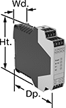
Safety Relays
Receive signals from safety monitoring relays or controllers to switch devices off and on because of a system failure. Also known as force-guided or mechanically linked contacts, the interlocking opposing contacts on these relays cannot be open or closed at the same time. To keep your system from receiving false switching signals, the interlocking opposing contact must remain open even if a contact welds closed.
IP20 rated, they have recessed terminals that prevent fingers and other objects from touching live circuits. These relays have been tested to safety standards that can help you achieve your system's PL (performance level) and SIL (safety integrity level). Choose a relay with a PL and SIL rating to meet the needs of your system. Higher ratings indicate greater safety protection. As your system becomes more complex, you generally require a higher safety protection level. Mount them to 35mm DIN rail (also known as DIN 3 Rail).
Relays that meet SIL2 are tested for applications with a probability of failure of 0.1% to 1%. They’re often used for emergency shutdowns, and fire, gas, and overpressure detection.
![]() For technical drawings and 3-D models, click on a part number.
For technical drawings and 3-D models, click on a part number.
| Number of Terminals | Input Voltage | Control Current, mA | Switching Current @ Voltage | Max. Switching Voltage | Ht. | Wd. | Dp. | Features | Each | |
With Screw Terminals—DIN-Rail Mount | ||||||||||
|---|---|---|---|---|---|---|---|---|---|---|
2 Circuits Controlled with 1 Off (Normally Open) and 1 On (Normally Closed)—DPST-1NO/1NC | ||||||||||
| 8 | 120V AC | 9 | 6 A @ 240 V AC | 250V AC | 3.4" | 0.9" | 3.9" | Interlocked Opposing Contacts, Recessed Terminals, LED Indicator | 00000000 | 000000 |
| 8 | 24V DC | 38 | 6 A @ 240 V AC | 250V AC | 3.4" | 0.9" | 3.9" | Interlocked Opposing Contacts, Recessed Terminals, LED Indicator | 00000000 | 00000 |
4 Circuits Controlled with 2 Off (Normally Open) and 2 On (Normally Closed)—4PST-2NO/2NC | ||||||||||
| 12 | 120V AC | 10 | 6 A @ 240 V AC | 250V AC | 3.4" | 0.9" | 3.9" | Interlocked Opposing Contacts, Recessed Terminals, LED Indicator | 00000000 | 000000 |
| 12 | 24V DC | 42 | 6 A @ 240 V AC | 250V AC | 3.4" | 0.9" | 3.9" | Interlocked Opposing Contacts, Recessed Terminals, LED Indicator | 00000000 | 000000 |
4 Circuits Controlled with 3 Off (Normally Open) and 1 On (Normally Closed)—4PST-3NO/1NC | ||||||||||
| 12 | 120V AC | 10 | 6 A @ 240 V AC | 250V AC | 3.4" | 0.9" | 3.9" | Interlocked Opposing Contacts, Recessed Terminals, LED Indicator | 00000000 | 000000 |
| 12 | 24V DC | 42 | 6 A @ 240 V AC | 250V AC | 3.4" | 0.9" | 3.9" | Interlocked Opposing Contacts, Recessed Terminals, LED Indicator | 00000000 | 000000 |
6 Circuits Controlled with 4 Off (Normally Open) and 2 On (Normally Closed)—6PDT-4NO/2NC | ||||||||||
| 16 | 120V AC | 10 | 6 A @ 240 V AC | 250V AC | 3.4" | 0.9" | 3.9" | Interlocked Opposing Contacts, Recessed Terminals, LED Indicator | 00000000 | 000000 |
| 16 | 24V DC | 42 | 6 A @ 240 V AC | 250V AC | 3.4" | 0.9" | 3.9" | Interlocked Opposing Contacts, Recessed Terminals, LED Indicator | 00000000 | 000000 |
6 Circuits Controlled with 5 Off (Normally Open) and 1 On (Normally Closed)—6PDT-5NO/1NC | ||||||||||
| 16 | 24V DC | 42 | 6 A @ 240 V AC | 250V AC | 3.4" | 0.9" | 3.9" | Interlocked Opposing Contacts, Recessed Terminals, LED Indicator | 00000000 | 000000 |
Safety Relays with Diagnostic Capabilities
Control and diagnose issues with safety-critical circuits. These relays have a microprocessor that monitors safety components, such as emergency stops and light curtains, and sends a signal to stop the operation if a failure is detected and restart when the issue is resolved. They also help with diagnostic tasks because of their feedback circuit, which allows basic relays to communicate their status back to the safety relay. These relays have a duplicate set of input and output signals, so they’ll still stop the controlled device if one of the inputs fails.
IP20 rated, they have recessed terminals which prevent fingers and other objects from touching live circuits. These relays have been tested to multiple safety standards and can help achieve PL, SIL, or CAT system ratings. They also meet ISO and IEC standards for machine safety.
Mount them to 35 mm DIN rail (also known as DIN 3 Rail) for fast installation.
Auxiliary contact blocks (sold separately) allow you to control more components, such as signaling devices or basic relays.
![]() For technical drawings and 3-D models, click on a part number.
For technical drawings and 3-D models, click on a part number.
| Number of Terminals | Input Voltage | Switching Current @ Voltage | Max. Switching Voltage | Ht. | Wd. | Dp. | For Use With | Max. System Safety Rating | Features | Each | |
3 Circuits Controlled | |||||||||||
|---|---|---|---|---|---|---|---|---|---|---|---|
3 Safety Outputs with 3 Off (Normally Open) | |||||||||||
| 6 | 24V DC | 6 A @ 240 V AC 6 A @ 24 V DC | 240V AC | 3.7" | 0.9" | 4.8" | Light Curtains | PLe, SIL3 | Auxiliary PNP Output, Self-Monitoring Circuitry | 0000000 | 0000000 |

| Number of Terminals | Input Voltage | Switching Current @ Voltage | Max. Switching Voltage | Ht. | Wd. | Dp. | Features | Each | |
5 Safety Outputs | |||||||||
|---|---|---|---|---|---|---|---|---|---|
| 16 | 24V AC, 24V DC | 2.5 A @ 24 V DC 3 A @ 240 V AC | 250V AC, 250V DC | 3.9" | 0.9" | 4.5" | __ | 0000000 | 0000000 |
4 Delayed Safety Outputs | |||||||||
| 16 | 24V DC | 3 A @ 240 V AC 3 A @ 24 V DC | 250V AC, 250V DC | 3.9" | 0.9" | 4.5" | Time Delay | 0000000 | 000000 |
Hazardous Location Relays
Sealed for safety, these relays are a good choice for hazardous locations where combustible or corrosive gases may be present.
Relays with screw terminals or spring-clamp terminals are considered interface relays, so they’re placed between your controller and components to isolate the input and output circuits. This means they protect your component from voltage spikes while amplifying the relay’s signal and reducing interference for reliable transmission. They are often used for switching applications, such as small motors and pilot lights. The included relay socket mounts on 35 mm DIN rail (also known as DIN 3 rail). Relays with spring-clamp terminals connect and disconnect to wires without needing to turn screws. With no screws to shake loose with vibration, the terminals hold tight over time.
![]() For technical drawings and 3-D models, click on a part number.
For technical drawings and 3-D models, click on a part number.
| Number of Terminals | Input Voltage | Control Current, mA | Switching Current @ Voltage | Max. Switching Voltage | Ht. | Wd. | Dp. | Environmental Rating | Each | |
Screw Terminals | ||||||||||
|---|---|---|---|---|---|---|---|---|---|---|
1 Circuit Controlled with 1 Off (Normally Open) or 1 On (Normally Closed)—SPDT | ||||||||||
| 5 | 12V AC, 12V DC | 15.5 | 6 A @ 240 V AC/30 V DC | 400V AC/125V DC | 2.9" | 0.2" | 3.5" | IP20; NEC Class I Division 2 Groups A, B, C, D | 00000000 | 000000 |
| 5 | 24V AC, 24V DC | 13.5 | 6 A @ 240 V AC/30 V DC | 400V AC/125V DC | 3.5" | 0.2" | 2.9" | IP20; NEC Class I Division 2 Groups A, B, C, D | 0000000 | 00000 |
| 5 | 48V AC, 48V DC | 4 | 6 A @ 240 V AC/30 V DC | 400V AC/125V DC | 3.5" | 0.2" | 2.9" | IP20; NEC Class I Division 2 Groups A, B, C, D | 0000000 | 00000 |
| 5 | 120V AC, 120V DC | 3.5 | 6 A @ 240 V AC/30 V DC | 400V AC/125V DC | 3.5" | 0.2" | 2.9" | IP20; NEC Class I Division 2 Groups A, B, C, D | 0000000 | 00000 |
| 5 | 240V AC, 240V DC | 3.5 | 6 A @ 240 V AC/30 V DC | 400V AC/125V DC | 3.5" | 0.2" | 2.9" | IP20; NEC Class I Division 2 Groups A, B, C, D | 0000000 | 00000 |
Spring-Clamp Terminals | ||||||||||
1 Circuit Controlled with 1 Off (Normally Open) or 1 On (Normally Closed)—SPDT | ||||||||||
| 5 | 12V AC, 12V DC | 15.5 | 6 A @ 240 V AC/30 V DC | 400V AC/125V DC | 2.9" | 0.2" | 3.7" | IP20; NEC Class I Division 2 Groups A, B, C, D | 0000000 | 00000 |
| 5 | 24V AC, 24V DC | 13.5 | 6 A @ 240 V AC/30 V DC | 400V AC/125V DC | 2.9" | 0.2" | 3.7" | IP20; NEC Class I Division 2 Groups A, B, C, D | 0000000 | 00000 |
| 5 | 120V AC, 120V DC | 3.5 | 6 A @ 240 V AC/30 V DC | 400V AC/125V DC | 2.9" | 0.2" | 3.7" | IP20; NEC Class I Division 2 Groups A, B, C, D | 0000000 | 00000 |
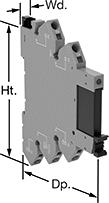
Solid State DIN-Rail Mount Multifunction Interface Timer Relays
Considered solid state because they don’t have any moving parts, these timer relays last longer, switch faster, and are quieter than mechanical relays. They interface between your controller and components to isolate input and output circuits, preventing damage to your components from voltage spikes, amplifying the relay's signal, and reducing signal interference. Use these relays with switching applications, such as small motors and pilot lights. They offer multiple timing functions in one relay. The included relay socket mounts on 35 mm DIN rail (also known as DIN 3 rail) for fast installation. Relays disconnect from the socket for easy replacement.
Relays with Relay Sockets | ||||||||||||||
|---|---|---|---|---|---|---|---|---|---|---|---|---|---|---|
Timing Range | Replacement Relays | |||||||||||||
| No. of Terminals | Input Voltage | Control Current, mA | Timer Relay Function | No. of | Overall | Switching Current @ Voltage | Max. Switching Voltage | Ht. | Wd. | Dp. | Each | Each | ||
1 Circuit Controlled with 1 Off (Normally Open)—SPST-NO | ||||||||||||||
| 5 | 24V AC, 24V DC | 12 | Delayed Start (Delay-on-Make) Interval Repeat Cycle | 4 | 0.1 sec.-6 hrs. | 6 A @ 24 V DC | 33V DC | 3 1/2" | 0.2" | 2.8" | 0000000 | 000000 | 0000000 | 000000 |
DIN-Rail Mount Multifunction Interface Timer Relays
Protect components from voltage spikes while amplifying the relay’s signal and reducing interference for reliable transmission—these relays interface between your controller and system components to isolate the input and output circuits. They are often used for switching applications, such as small motors and pilot lights. These relays provide a variety of timing functions in one relay. The included relay socket mounts on 35 mm DIN rail (also known as DIN 3 rail) for fast installation. Relays disconnect from the socket for easy replacement.
Relays with Relay Sockets | ||||||||||||||
|---|---|---|---|---|---|---|---|---|---|---|---|---|---|---|
Timing Range | Replacement Relays | |||||||||||||
| No. of Terminals | Input Voltage | Control Current, mA | Timer Relay Function | No. of | Overall | Switching Current @ 240V AC | Max. Switching Voltage | Ht. | Wd. | Dp. | Each | Each | ||
1 Circuit Controlled with 1 Off (Normally Open) or 1 On (Normally Closed)—SPDT | ||||||||||||||
| 5 | 24V AC, 24V DC | 16 | Delayed Start (Delay-on-Make) Interval Repeat Cycle | 4 | 0.1 sec.-6 hrs. | 6A | 240V AC | 3 1/2" | 0.2" | 2.8" | 0000000 | 000000 | 0000000 | 00000 |
High-Starting-Current DIN-Rail Mount Timer Relays

Reduce voltage fluctuations and stress on shafts and bearings when starting up three-phase motors. These timer relays start with motor contacts in a star configuration, then switch to a delta configuration after a set delay. Since star configuration takes less voltage to start than delta, these relays prevent voltage dips that often happen when a motor starts and are gentler on mechanical parts. Mount these relays directly to 35 mm DIN rail (also known as DIN 3 rail) for quick installation.
![]() For technical drawings and 3-D models, click on a part number.
For technical drawings and 3-D models, click on a part number.
Timing Range | ||||||||||||
|---|---|---|---|---|---|---|---|---|---|---|---|---|
| No. of Terminals | Input Voltage | Control Current, mA | Timer Relay Function | No. of | Overall | Switching Current @ 240V AC | Max. Switching Voltage | Ht. | Wd. | Dp. | Each | |
2 Circuits Controlled with 2 Off (Normally Open)—DPST-NO | ||||||||||||
| 5 | 24V AC, 48V AC, 120V AC, 240V AC, 24V DC, 30V DC, 48V DC, 60V DC, 120V DC, 240V DC | 5 | Star-to-Delta | 6 | 0.1 sec.-20 min. | 6A | 250V AC | 3.4" | 0.7" | 2.4" | 0000000 | 000000 |