


Choosing an Electrical Switch
More
DIN-Rail Mount Solid State Relays
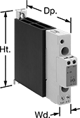
Unlike mechanical relays, these solid state relays have no moving parts, so they require less maintenance and last longer, switch faster, and are quieter. They mount on 35 mm DIN rail (also known as DIN 3) for fast installation. An LED indicator lights up when these relays are connected, so you can quickly confirm that they’re wired correctly. IP20 rated, their terminals are recessed, so they prevent fingers and other objects from touching live circuits.
Relays with an integrated heat sink disperse heat to increase the relay’s current rating.
![]() For technical drawings and 3-D models, click on a part number.
For technical drawings and 3-D models, click on a part number.
| Number of Terminals | Input Voltage | Control Current, mA | Switching Current @ Voltage (Load Type) | Max. Switching Voltage | hp @ Switching Voltage | Ht. | Wd. | Dp. | Features | Each | |
1 Circuit Controlled with 1 Off (Normally Open)—SPST-NO | |||||||||||
|---|---|---|---|---|---|---|---|---|---|---|---|
Single Phase | |||||||||||
| 4 | 24V AC, 120V AC, 208V AC, 240V AC, 277V AC/24V DC, 48V DC, 60V DC, 120V DC | 13 | 20 A @ 240 V AC (Full Load) | 264V AC | 1/3 hp @ 115 V AC 1 hp @ 230 V AC | 4.33" | 0.7" | 3.447" | Integrated Heat Sink, LED Indicator | 0000000 | 000000 |
| 4 | 24V AC, 120V AC, 208V AC, 240V AC, 277V AC/24V DC, 48V DC, 60V DC, 120V DC | 13 | 20 A @ 600 V AC (Full Load) | 660V AC | 1/3 hp @ 115 V AC 1 hp @ 230 V AC | 4.33" | 0.7" | 3.447" | Integrated Heat Sink, LED Indicator | 0000000 | 00000 |
| 4 | 3V DC, 6V DC, 12V DC, 24V DC, 30V DC | 11 | 20 A @ 240 V AC (Full Load) | 264V AC | 1/3 hp @ 115 V AC 1 hp @ 230 V AC | 4.33" | 0.7" | 3.447" | Integrated Heat Sink, LED Indicator | 0000000 | 00000 |
| 4 | 4V DC, 6V DC, 12V DC, 24V DC, 30V DC | 10 | 20 A @ 600 V AC (Full Load) | 660V AC | 1/3 hp @ 115 V AC 1 hp @ 230 V AC | 4.33" | 0.7" | 3.447" | Integrated Heat Sink, LED Indicator | 0000000 | 00000 |
3 Circuits Controlled with 3 Off (Normally Open)—3PST-NO | |||||||||||
Three Phase | |||||||||||
| 4 | 24V AC, 120V AC, 208V AC, 240V AC, 277V AC/24V DC, 48V DC, 60V DC, 120V DC | 2 | 20 A @ 600 V AC (Full Load) | 660V AC | 3 hp @ 230 V AC 7 1/2 hp @ 480 V AC | 4.33" | 2.1" | 3.427" | Integrated Heat Sink, LED Indicator | 0000000 | 000000 |
| 4 | 5V DC, 6V DC, 12V DC, 24V DC, 30V DC | 10 | 20 A @ 600 V AC (Full Load) | 660V AC | 3 hp @ 230 V AC 7 1/2 hp @ 480 V AC | 4.33" | 2.1" | 3.427" | Integrated Heat Sink, LED Indicator | 0000000 | 000000 |
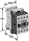
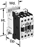
DIN-Rail Mount Touch-Safe Screw Terminal Relays
Quickly and safely mount these relays on 35 mm DIN rail (also known as DIN 3). IP20 rated, they have recessed terminals that prevent fingers and other objects from touching live circuits.
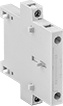
Relays that control 3 and 4 circuits are built to IEC dimensional standards and are often called IEC contactors. Auxiliary contacts (sold separately) allow you to add a signaling device or control another relay. You can add one auxiliary contact to all of these relays. For relays with 12 terminals, you can add two side-mount auxiliary contacts.
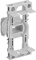
Use replacement coils to swap out a broken coil or change the input voltage of a relay. They are only compatible with relays that have 12 terminals. The full load current of the relay must match the full load current range of the coil.
![]() For technical drawings and 3-D models, click on a part number.
For technical drawings and 3-D models, click on a part number.
Control | hp @ Switching Voltage | ||||||||||
|---|---|---|---|---|---|---|---|---|---|---|---|
| Number of Terminals | Input Voltage | Power | Switching Current @ Voltage (Load Type) | Max. Switching Voltage | Single Phase | Three Phase | Ht. | Wd. | Dp. | Each | |
3 Circuits Controlled with 3 Off (Normally Open)—3PST-NO | |||||||||||
With 1 Auxiliary Contact—1 Off (Normally Open) | |||||||||||
| 10 | 24V AC | 4VA | 6 A @ 600 V AC (Full Load) 20 A @ 600 V AC (Resistive Load) | 600 V AC | 1 1/2 hp @ 240 V AC 1/2 hp @ 120 V AC | 3 hp @ 240 V AC 5 hp @ 480 V AC 5 hp @ 600 V AC | 2.3" | 1.7" | 2.2" | 000000000 | 000000 |
| 10 | 120V AC | 4VA | 6 A @ 600 V AC (Full Load) 20 A @ 600 V AC (Resistive Load) | 600 V AC | 1 1/2 hp @ 240 V AC 1/2 hp @ 120 V AC | 3 hp @ 240 V AC 5 hp @ 480 V AC 5 hp @ 600 V AC | 2.3" | 1.7" | 2.2" | 000000000 | 00000 |
| 10 | 240V AC | 4VA | 6 A @ 600 V AC (Full Load) 20 A @ 600 V AC (Resistive Load) | 600 V AC | 1 1/2 hp @ 240 V AC 1/2 hp @ 120 V AC | 3 hp @ 240 V AC 5 hp @ 480 V AC 5 hp @ 600 V AC | 2.3" | 1.7" | 2.2" | 000000000 | 00000 |
| 10 | 24V DC | 3.2W | 6 A @ 600 V AC (Full Load) 20 A @ 600 V AC (Resistive Load) | 600 V AC | 1 1/2 hp @ 240 V AC 1/2 hp @ 120 V AC | 3 hp @ 240 V AC 5 hp @ 480 V AC 5 hp @ 600 V AC | 2.3" | 1.7" | 2.2" | 00000000 | 00000 |
With 1 Auxiliary Contact—1 On (Normally Closed) | |||||||||||
| 10 | 24V AC | 4VA | 6 A @ 600 V AC (Full Load) 20 A @ 600 V AC (Resistive Load) | 600 V AC | 1 1/2 hp @ 240 V AC 1/2 hp @ 120 V AC | 3 hp @ 240 V AC 5 hp @ 480 V AC 5 hp @ 600 V AC | 2.3" | 1.7" | 2.2" | 000000000 | 00000 |
| 10 | 120V AC | 4VA | 6 A @ 600 V AC (Full Load) 20 A @ 600 V AC (Resistive Load) | 600 V AC | 1 1/2 hp @ 240 V AC 1/2 hp @ 120 V AC | 3 hp @ 240 V AC 5 hp @ 480 V AC 5 hp @ 600 V AC | 2.3" | 1.7" | 2.2" | 000000000 | 00000 |
| 10 | 240V AC | 4VA | 6 A @ 600 V AC (Full Load) 20 A @ 600 V AC (Resistive Load) | 600 V AC | 1 1/2 hp @ 240 V AC 1/2 hp @ 120 V AC | 3 hp @ 240 V AC 5 hp @ 480 V AC 5 hp @ 600 V AC | 2.3" | 1.7" | 2.2" | 000000000 | 00000 |
| 10 | 24V DC | 3.2W | 6 A @ 600 V AC (Full Load) 20 A @ 600 V AC (Resistive Load) | 600 V AC | 1 1/2 hp @ 240 V AC 1/2 hp @ 120 V AC | 3 hp @ 240 V AC 5 hp @ 480 V AC 5 hp @ 600 V AC | 2.3" | 1.7" | 2.2" | 00000000 | 00000 |

| Number of Circuits Controlled | For Relay Width | Switch Starting Position | Industry Designation | Mounting Location | Each | |
| 2 | 1.7" | 1 Off (Normally Open) and 1 On (Normally Closed) | DPST-1NO/1NC | Front | 00000000 | 000000 |
Open-Style Screw Terminal Relays

Optional covers protect contacts from dust and dirt.
Relays | Optional Covers | |||||||||||
|---|---|---|---|---|---|---|---|---|---|---|---|---|
| Number of Terminals | Input Voltage | Control Current, mA | Switching Current @ Voltage | Max. Switching Voltage | hp @ Switching Voltage | Ht. | Wd. | Dp. | Each | Each | ||
4 Circuits Controlled with 4 Off (Normally Open) or 4 On (Normally Closed)—4PDT | ||||||||||||
| 14 | 120V AC | 116 | 35 A @ 120 V AC 20 A @ 24 V DC | 120V AC | 1 hp @ 120 V AC 1 1/2 hp @ 240 V AC | 3.4" | 2.7" | 2.7" | 0000000 | 0000000 | 0000000 | 0000000 |
Infrequent-Cycle Relays


For use with equipment that cycles on and off, these relays meet UL 508 for air conditioning and heating. Connections are accessible from the front, so you can mount relays side-by-side. Also known as definite-purpose contactors.
Also Available: Auxiliary contacts for 3.8"-7.2" Ht. relays. They allow you to add a signaling device or control another relay. Please select 6564K99, then select the McMaster-Carr part number of your relay and whether you want to switch one circuit on (1 Normally Open) or off (1 Normally Closed).
![]() For technical drawings and 3-D models, click on a part number.
For technical drawings and 3-D models, click on a part number.
Switching Current @ 600V AC | hp @ Switching Voltage | |||||||||||
|---|---|---|---|---|---|---|---|---|---|---|---|---|
| Number of Terminals | Input Voltage | Control Power | Full Load | Resistive Load | Single Phase | Three Phase | Ht. | Wd. | Dp. | Quick-Disconnect Tab Wd. | Each | |
2 Circuits Controlled with 2 Off (Normally Open)—DPST-NO | ||||||||||||
With Quick-Disconnect and Screw Terminals | ||||||||||||
| 4 | 24V AC | 6.5VA | 20A | 30A | 1 1/2 hp @ 115 V AC 3 hp @ 230 V AC | __ | 3.2" | 2" | 2.3" | 0.25" | 00000000 | 000000 |
| 4 | 24V AC | 7VA | 15A | 20A | 3/4 hp @ 115 V AC 2 hp @ 230 V AC | 3 hp @ 230 V AC 5 hp @ 460 V AC 5 hp @ 575 V AC | 3.8" | 2.4" | 3.4" | 0.25" | 00000000 | 00000 |
| 4 | 120V AC | 6.5VA | 20A | 30A | 1 1/2 hp @ 115 V AC 3 hp @ 230 V AC | __ | 3.2" | 2" | 2.3" | 0.25" | 00000000 | 00000 |
| 4 | 120V AC | 7VA | 15A | 20A | 3/4 hp @ 115 V AC 2 hp @ 230 V AC | 3 hp @ 230 V AC 5 hp @ 460 V AC 5 hp @ 575 V AC | 3.8" | 2.4" | 3.4" | 0.25" | 00000000 | 00000 |
| 4 | 24V DC | 3.1W | 15A | 20A | 3/4 hp @ 115 V AC 2 hp @ 230 V AC | 3 hp @ 230 V AC 5 hp @ 460 V AC 5 hp @ 575 V AC | 3.8" | 2.4" | 3.4" | 0.25" | 00000000 | 000000 |
| 4 | 208V AC, 240V AC | 6.5VA | 20A | 30A | 1 1/2 hp @ 115 V AC 3 hp @ 230 V AC | __ | 3.2" | 2" | 2.3" | 0.25" | 00000000 | 00000 |
| 4 | 208V AC, 240V AC | 7VA | 15A | 20A | 3/4 hp @ 115 V AC 2 hp @ 230 V AC | 3 hp @ 230 V AC 5 hp @ 460 V AC 5 hp @ 575 V AC | 3.8" | 2.4" | 3.4" | 0.25" | 00000000 | 00000 |
3 Circuits Controlled with 3 Off (Normally Open)—3PST-NO | ||||||||||||
With Quick-Disconnect and Screw Terminals | ||||||||||||
| 6 | 24V AC | 7VA | 15A | 20A | 3/4 hp @ 115 V AC 2 hp @ 230 V AC | 3 hp @ 230 V AC 5 hp @ 460 V AC 5 hp @ 575 V AC | 3.8" | 2.4" | 3.4" | 0.25" | 00000000 | 000000 |
| 6 | 120V AC | 7VA | 15A | 20A | 3/4 hp @ 115 V AC 2 hp @ 230 V AC | 3 hp @ 230 V AC 5 hp @ 460 V AC 5 hp @ 575 V AC | 3.8" | 2.4" | 3.4" | 0.25" | 00000000 | 000000 |
| 6 | 24V DC | 3.1W | 15A | 20A | 3/4 hp @ 115 V AC 2 hp @ 230 V AC | 3 hp @ 230 V AC 5 hp @ 460 V AC 5 hp @ 575 V AC | 3.8" | 2.4" | 3.4" | 0.25" | 00000000 | 000000 |
| 6 | 208V AC, 240V AC | 7VA | 15A | 20A | 3/4 hp @ 115 V AC 2 hp @ 230 V AC | 3 hp @ 230 V AC 5 hp @ 460 V AC 5 hp @ 575 V AC | 3.8" | 2.4" | 3.4" | 0.25" | 00000000 | 000000 |
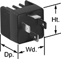
High-Starting-Current Vehicle Relays


Crimp-On
Terminals
Also known as automotive relays, these relays can handle high starting (inrush) currents.
Relays for surface mounting have a tab for added security in high-vibration applications.
Relays | ||||||||||||||||
|---|---|---|---|---|---|---|---|---|---|---|---|---|---|---|---|---|
Switching Current @ Voltage | Relay Sockets with Crimp-On Terminals | Relay Sockets with Wire Leads | ||||||||||||||
| Number of Terminals | Input Voltage | Off (Normally Open) Circuit Position | On (Normally Closed) Circuit Position | Max. Switching Voltage | Max. Starting Current, A | Control Current, mA | Ht. | Wd. | Dp. | Quick-Disconnect Tab Wd. | Each | Each | Each | |||
For Relay Socket | ||||||||||||||||
1 Circuit Controlled with 1 Off (Normally Open)—SPST-NO | ||||||||||||||||
| 5 | 24V DC | 20 A @ 24 V DC | __ | 40V DC | 120 | 69 | 1" | 1" | 0.9" | 0.25" | 0000000 | 00000 | 0000000 | 00000 | 0000000 | 000000 |
1 Circuit Controlled with 1 Off (Normally Open) or 1 On (Normally Closed)—SPDT | ||||||||||||||||
| 5 | 12V DC | 30 A @ 12 V DC | 20 A @ 12 V DC | 18V DC | 150 | 138 | 1.02" | 1.02" | 0.94" | 0.25" | 0000000 | 0000 | 0000000 | 0000 | 0000000 | 00000 |
| 5 | 24V DC | 20 A @ 24 V DC | 10 A @ 24 V DC | 36V DC | 150 | 99 | 1" | 1" | 1" | 0.25" | 0000000 | 0000 | 0000000 | 0000 | 0000000 | 00000 |
For Relay Socket and Surface Mounting | ||||||||||||||||
1 Circuit Controlled with 1 Off (Normally Open) or 1 On (Normally Closed)—SPDT | ||||||||||||||||
| 5 | 12V DC | 30 A @ 12 V DC | 20 A @ 12 V DC | 18V DC | 150 | 138 | 1.1" | 1.1" | 1" | 0.25" | 0000000 | 0000 | 0000000 | 0000 | 0000000 | 00000 |
| 5 | 24V DC | 20 A @ 24 V DC | 10 A @ 24 V DC | 40V DC | 120 | 109 | 1" | 1" | 0.9" | 0.25" | 0000000 | 00000 | 0000000 | 0000 | 0000000 | 00000 |
Weatherproof High-Starting-Current Vehicle Relays


Crimp-On
Terminals
An extended housing shields the terminals on these relays from weather. They're also rated IP54—when they're plugged into the relay socket, they're sealed to keep splashing water, like rain, from getting inside. They handle high starting (inrush) currents that often occur when turning on a vehicle. To prevent damage to sensitive equipment, these relays will partially suppress a momentary surge in voltage when the relay switches off. They’ll take a voltage spike of 300V to 500V and bring it down to 100V.
Relays for surface mounting have a tab for added security in high-vibration applications.
Relays | ||||||||||||||||
|---|---|---|---|---|---|---|---|---|---|---|---|---|---|---|---|---|
Switching Current @ Voltage | Relay Sockets with Crimp-On Terminals | Relay Sockets with Wire Leads | ||||||||||||||
| Number of Terminals | Input Voltage | Off (Normally Open) Circuit Position | On (Normally Closed) Circuit Position | Max. Switching Voltage | Max. Starting Current, A | Control Current, mA | Ht. | Wd. | Dp. | Quick-Disconnect Tab Wd. | Each | Each | Each | |||
For Relay Socket | ||||||||||||||||
1 Circuit Controlled with 1 Off (Normally Open) or 1 On (Normally Closed)—SPDT | ||||||||||||||||
| 5 | 12V DC | 40 A @ 12 V DC | 20 A @ 12 V DC | 18V DC | 150 | 114 | 1.4" | 1.4" | 1.8" | 0.11" | 00000000 | 000000 | 000000 | 00 | 00000000 | 000000 |
| 5 | 12V DC | 40 A @ 12 V DC | 20 A @ 12 V DC | 18V DC | 150 | 155 | 1.4" | 1.4" | 1.8" | 0.25" | 00000000 | 00000 | 0000000 | 000000 | 0000000 | 00000 |
For Relay Socket and Surface Mounting | ||||||||||||||||
1 Circuit Controlled with 1 Off (Normally Open) or 1 On (Normally Closed)—SPDT | ||||||||||||||||
| 5 | 12V DC | 40 A @ 12 V DC | 20 A @ 12 V DC | 18V DC | 150 | 114 | 1.4" | 1.4" | 1.8" | 0.11" | 00000000 | 00000 | 000000 | 00 | 00000000 | 00000 |
| 5 | 12V DC | 40 A @ 12 V DC | 20 A @ 12 V DC | 18V DC | 150 | 138 | 1.4" | 1.4" | 1.8" | 0.25" | 0000000 | 00000 | 0000000 | 00000 | 0000000 | 00000 |
| 5 | 24V DC | 20 A @ 24 V DC | 10 A @ 24 V DC | 40V DC | 120 | 107 | 1.4" | 1.4" | 1.8" | 0.25" | 0000000 | 00000 | 0000000 | 00000 | 0000000 | 00000 |
Solid State High-Starting-Current Vehicle Relays
Crimp-On
Terminals
With no moving parts, these solid state relays require less maintenance and last longer, switch faster, and are quieter than mechanical relays. They can handle high starting (inrush) currents. The blade terminals meet ISO 8092-1 dimensions, ensuring they are compatible with the electrical connections in road vehicles you need to maintain or repair. Also known as ISO relays or automotive relays.
Relays | Relay Sockets with Crimp-On Terminals | Relay Sockets with Wire Leads | |||||||||||||
|---|---|---|---|---|---|---|---|---|---|---|---|---|---|---|---|
| Number of Terminals | Input Voltage | Switching Current @ 12V DC | Max. Switching Voltage | Max. Starting Current, A | Control Current, mA | Ht. | Wd. | Dp. | Quick-Disconnect Tab Wd. | Each | Each | Each | |||
1 Circuit Controlled with 1 Off (Normally Open)—SPST-NO | |||||||||||||||
| 4 | 12V DC | 20A | 16V DC | 80 | 10 | 1.1" | 1.1" | 1" | 0.25" | 0000000 | 000000 | 0000000 | 00000 | 0000000 | 000000 |
Safety Relays

Receive signals from safety monitoring relays or controllers to switch devices off and on because of a system failure. When a failure is detected, the self-monitoring circuitry signals the controller to remove power and prevent restarting until the issue is resolved. An inspection window allows you to easily see the status of your system.
These relays have nondetachable auxiliary contacts, so they won’t separate from the relay if there is shock or vibration. Also known as force-guided or mechanically linked contacts, their interlocking opposing auxiliary contacts cannot be open or closed at the same time. They have mirror auxiliary contacts, which are normally closed and cannot be open at the same time as a normally open main contact. To keep your system from receiving false switching signals, the interlocking opposing auxiliary contact must remain open even if a contact welds closed.
IP20 rated, they have recessed terminals which prevent fingers and other objects from touching live circuits. These relays have been tested to multiple safety standards and can help achieve PL, SIL, and CAT system ratings. They also meet ISO and IEC standards for machine safety.
Mount them to 35mm DIN rail (also known as DIN 3 Rail). They can also be mounted to flat surfaces.
![]() For technical drawings and 3-D models, click on a part number.
For technical drawings and 3-D models, click on a part number.
hp @ Switching Voltage | |||||||||||||
|---|---|---|---|---|---|---|---|---|---|---|---|---|---|
| Number of Terminals | Input Voltage | Control Current, A | Switching Current @ 600V AC | Max. Switching Voltage | Single Phase | Three Phase | Auxiliary Contact Switch Starting Position (No. of Contacts) | Ht. | Wd. | Dp. | Max. System Safety Rating | Each | |
3 Circuits Controlled with 3 Off (Normally Open) or 3 On (Normally Closed)—3PST | |||||||||||||
| 18 | 120V AC | 7 | 20A | 600V AC | 1/4 hp @ 120 V AC 1 hp @ 240 V AC | 2 hp @ 240 V AC 3 hp @ 480 V AC 5 hp @ 600 V AC | 1 Off (Normally Open) (2) 1 On (Normally Closed) (3) | 2.68" | 1.77" | 4.6" | PLe, SIL3, CAT 4, 600V | 0000000 | 0000000 |
| 18 | 120V AC | 9 | 20A | 600V AC | 1/2 hp @ 120 V AC 1 1/2 hp @ 240 V AC | 3 hp @ 240 V AC 5 hp @ 480 V AC 7 1/2 hp @ 600 V AC | 1 Off (Normally Open) (2) 1 On (Normally Closed) (3) | 2.68" | 1.77" | 4.6" | PLe, SIL3, CAT 4, 600V | 0000000 | 000000 |
| 18 | 120V AC | 12 | 20A | 600V AC | 1 hp @ 120 V AC 2 hp @ 240 V AC | 3 hp @ 240 V AC 10 hp @ 480 V AC 10 hp @ 600 V AC | 1 Off (Normally Open) (2) 1 On (Normally Closed) (3) | 2.68" | 1.77" | 4.6" | PLe, SIL3, CAT 4, 600V | 0000000 | 000000 |
| 18 | 24V DC | 7 | 20A | 600V AC | 1/4 hp @ 120 V AC 1 hp @ 240 V AC | 2 hp @ 240 V AC 3 hp @ 480 V AC 5 hp @ 600 V AC | 1 Off (Normally Open) (2) 1 On (Normally Closed) (3) | 2.68" | 1.77" | 4.6" | PLe, SIL3, CAT 4, 600V | 0000000 | 000000 |
| 18 | 24V DC | 9 | 20A | 600V AC | 1/2 hp @ 120 V AC 1 1/2 hp @ 240 V AC | 3 hp @ 240 V AC 5 hp @ 480 V AC 7 1/2 hp @ 600 V AC | 1 Off (Normally Open) (2) 1 On (Normally Closed) (3) | 2.68" | 1.77" | 4.6" | PLe, SIL3, CAT 4, 600V | 0000000 | 000000 |
| 18 | 24V DC | 12 | 20A | 600V AC | 1 hp @ 120 V AC 2 hp @ 240 V AC | 3 hp @ 240 V AC 10 hp @ 480 V AC 10 hp @ 600 V AC | 1 Off (Normally Open) (2) 1 On (Normally Closed) (3) | 2.68" | 1.77" | 4.6" | PLe, SIL3, CAT 4, 600V | 0000000 | 000000 |
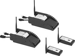
Wireless Enclosed Relays
Send a signal to turn equipment on and off from up to 150 feet away without having to run electrical wire. These relays have an enclosure to protect the terminals from dust and accidental bumps. They can be set to transmit, receive, or both at once. You’ll need at least two relays to switch a device. They have an alarm that can be set to check for certain conditions before transmitting a signal. For example, you could set these relays to send a signal to turn on an air conditioner if all windows are closed. The repeat function extends the transmitting signal through a maximum of two receiving relays.
Relays that are set to transmit can be linked up to as many receiving relays as you need. Relays set to receive can be linked up to 30 transmitting relays. All relays connect to dry contacts on your switch, sensor, or controller. Use the wire leads to connect them to a power source.
UL and C-UL listed, all meet American and Canadian safety standards. Rated NEMA 1, they should only be used indoors.
![]() For technical drawings and 3-D models, click on a part number.
For technical drawings and 3-D models, click on a part number.
Wire Lead | Conduit Connection | |||||||||||||||
|---|---|---|---|---|---|---|---|---|---|---|---|---|---|---|---|---|
| Input Voltage | Control Current | Switching Current @ 277V AC | Maximum Switching Voltage | hp @ Switching Voltage | Ht. | Wd. | Dp. | Maximum Transmission Distance, ft. | Lg. | Number of | Gender | Trade Size | Thread Type | Environmental Rating | Each | |
1 Circuit Controlled with 1 Off (Normally Open) or 1 On (Normally Closed)—SPDT | ||||||||||||||||
| 120V AC | 73 | 20A | 277V AC | 2 hp @ 277 V AC | 2.3" | 3.2" | 1.8" | 150 | 16" | 7 | Male | 1/2 | NPT | NEMA 1 | 0000000 | 0000000 |
| 208V AC | 80 | 20A | 277V AC | 2 hp @ 277 V AC | 2.3" | 3.2" | 1.8" | 150 | 16" | 7 | Male | 1/2 | NPT | NEMA 1 | 0000000 | 000000 |
| 240V AC | 80 | 20A | 277V AC | 2 hp @ 277 V AC | 2.3" | 3.2" | 1.8" | 150 | 16" | 7 | Male | 1/2 | NPT | NEMA 1 | 0000000 | 000000 |
| 277V AC | 80 | 20A | 277V AC | 2 hp @ 277 V AC | 2.3" | 3.2" | 1.8" | 150 | 16" | 7 | Male | 1/2 | NPT | NEMA 1 | 0000000 | 000000 |
| 24V AC, 24V DC | 69 | 20A | 277V AC | 2 hp @ 277 V AC | 2.3" | 3.2" | 1.8" | 150 | 16" | 7 | Male | 1/2 | NPT | NEMA 1 | 0000000 | 000000 |
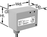
Enclosed Relays
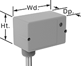
An enclosure covers the terminals on these relays to help prevent damage from dust or accidental bumps. They have an LED indicator, so you can quickly see what switching position your relay is in. Hardwire them to your equipment with the included wire leads. Rated NEMA 1, these relays are intended for indoor use only.
![]() For technical drawings and 3-D models, click on a part number.
For technical drawings and 3-D models, click on a part number.
Wire Lead | Conduit Connection | ||||||||||||||
|---|---|---|---|---|---|---|---|---|---|---|---|---|---|---|---|
| Input Voltage | Control Current, mA | Switching Current @ 277V AC | Max. Switching Voltage | hp @ Switching Voltage | Ht. | Wd. | Dp. | Lg. | Number of | Gender | Trade Size | Thread Type | Environmental Rating | Each | |
1 Circuit Controlled with 1 Off (Normally Open) or 1 On (Normally Closed)—SPDT | |||||||||||||||
| 24V AC, 120V AC, 208V AC, 240V AC, 277V AC, 30V DC | 47 | 20A | 277V AC | 1 hp @ 120 V AC 2 hp @ 277 V AC | 2.4" | 3.3" | 1.8" | 16" | 6 | Male | 1/2 | NPT | NEMA 1 | 0000000 | 000000 |
2 Circuits Controlled with 2 Off (Normally Open) or 2 On (Normally Closed)—DPDT | |||||||||||||||
| 24V AC, 208V AC, 240V AC, 277V AC, 30V DC | 140 | 20A | 277V AC | 1 hp @ 120 V AC 2 hp @ 277 V AC | 2.4" | 3.3" | 1.8" | 16" | 8 | Male | 3/4 | NPT | NEMA 1 | 0000000 | 00000 |
| 120V AC | 105 | 20A | 277V AC | 1 hp @ 120 V AC 2 hp @ 277 V AC | 4" | 4" | 1.8" | 16" | 8 | Male | 1/2 | NPT | NEMA 1 | 0000000 | 00000 |
Touch-Safe DIN-Rail Mount Infrequent-Cycle Relays
Operate equipment that cycles on and off from your control cabinet. Often called definite-purpose contactors, these relays meet UL 508 for use with air conditioning and heating. Mount them directly to 35 mm DIN rail (also known as DIN 3 rail) for fast installation. They have recessed terminals that prevent fingers and other objects from touching live circuits. You can wire the control circuit on either side of the relay, which helps you use less wire.
Auxiliary contacts (sold separately) allow you to add a signaling device or control another relay.
Use replacement coils to swap out a broken coil or change the input voltage of a relay. The full load current of the relay must match the full load current range of the coil.
![]() For technical drawings and 3-D models, click on a part number.
For technical drawings and 3-D models, click on a part number.
Switching Current @ 600V AC | hp @ Switching Voltage | |||||||||||
|---|---|---|---|---|---|---|---|---|---|---|---|---|
| Number of Terminals | Input Voltage | Control Power | Full Load | Resistive Load | Max. Switching Voltage | Single Phase | Three Phase | Ht. | Wd. | Dp. | Each | |
Relays | ||||||||||||
4 Circuits Controlled with 4 Off (Normally Open)—4PST-NO | ||||||||||||
| 12 | 24V AC | 9VA | 20A | 30A | 600V AC | 1 1/2 hp @ 120 V AC 3 hp @ 240 V AC | 5 hp @ 240 V AC 10 hp @ 480 V AC 15 hp @ 600 V AC | 3.2" | 1.8" | 3.2" | 00000000 | 000000 |
| 12 | 120V AC | 9VA | 20A | 30A | 600V AC | 1 1/2 hp @ 120 V AC 3 hp @ 240 V AC | 5 hp @ 240 V AC 10 hp @ 480 V AC 15 hp @ 600 V AC | 3.2" | 1.8" | 3.2" | 00000000 | 00000 |
| 12 | 240V AC | 9VA | 20A | 30A | 600V AC | 1 1/2 hp @ 120 V AC 3 hp @ 240 V AC | 5 hp @ 240 V AC 10 hp @ 480 V AC 15 hp @ 600 V AC | 3.2" | 1.8" | 3.2" | 00000000 | 00000 |
| 12 | 24V DC | 5.4W | 20A | 30A | 600V AC | 1 1/2 hp @ 120 V AC 3 hp @ 240 V AC | 5 hp @ 240 V AC 10 hp @ 480 V AC 15 hp @ 600 V AC | 3.2" | 1.8" | 3.9" | 0000000 | 000000 |
Relays with 1 Off (Normally Open) Auxiliary Contact | ||||||||||||
3 Circuits Controlled with 3 Off (Normally Open)—3PST-NO | ||||||||||||
| 12 | 24V AC | 9VA | 20A | 30A | 600V AC | 1 1/2 hp @ 120 V AC 3 hp @ 240 V AC | 5 hp @ 240 V AC 10 hp @ 480 V AC 15 hp @ 600 V AC | 3.2" | 1.8" | 3.2" | 00000000 | 00000 |
| 12 | 120V AC | 9VA | 20A | 30A | 600V AC | 1 1/2 hp @ 120 V AC 3 hp @ 240 V AC | 5 hp @ 240 V AC 10 hp @ 480 V AC 15 hp @ 600 V AC | 3.2" | 1.8" | 3.2" | 00000000 | 00000 |
| 12 | 240V AC | 9VA | 20A | 30A | 600V AC | 1 1/2 hp @ 120 V AC 3 hp @ 240 V AC | 5 hp @ 240 V AC 10 hp @ 480 V AC 15 hp @ 600 V AC | 3.2" | 1.8" | 3.2" | 00000000 | 00000 |
| 12 | 24V DC | 5.4W | 20A | 30A | 600V AC | 1 1/2 hp @ 120 V AC 3 hp @ 240 V AC | 5 hp @ 240 V AC 10 hp @ 480 V AC 15 hp @ 600 V AC | 3.2" | 1.8" | 3.9" | 0000000 | 000000 |
| Number of Circuits Controlled | For Relay Width | Switch Starting Position | Industry Designation | Mounting Location | Each | |
| 2 | 1.8", 2.2", 2.4" | 2 Off (Normally Open) | DPST-NO | Front | 0000000 | 000000 |
| 2 | 1.8", 2.2", 2.4" | 2 On (Normally Closed) | DPST-NC | Front | 0000000 | 00000 |
| 2 | 1.8", 2.4" | 1 Off (Normally Open) and 1 On (Normally Closed) | DPST-1NO/1NC | Front | 00000000 | 00000 |
| 2 | 1.8", 2.4" | 1 Off (Normally Open) and 1 On (Normally Closed) | DPST-1NO/1NC | Side | 00000000 | 00000 |
| 4 | 1.8", 2.2", 2.4" | 1 Off (Normally Open) and 3 On (Normally Closed) | 4PST-1NO/3NC | Front | 0000000 | 00000 |
| 4 | 1.8", 2.2", 2.4" | 2 Off (Normally Open) and 2 On (Normally Closed) | 4PST-2NO/2NC | Front | 0000000 | 00000 |
| 4 | 1.8", 2.2", 2.4" | 3 Off (Normally Open) and 1 On (Normally Closed) | 4PST-3NO/1NC | Front | 0000000 | 00000 |
| 4 | 1.8", 2.2", 2.4" | 4 Off (Normally Open) | 4PST-NO | Front | 0000000 | 00000 |
| 4 | 1.8", 2.2", 2.4" | 4 On (Normally Closed) | 4PST-NC | Front | 0000000 | 00000 |
Analog-Input Proportional-Control Relays

Often used to regulate the speed of AC fans or keep a heater at a set temperature, these relays connect directly to sensors to calculate and adjust output power. This allows you to use an analog input without converting it to a digital signal to control output power. They are solid state and have no moving parts, so they require less maintenance and last longer, are quieter, and switch faster than mechanical relays. IP20 rated, they have recessed terminals that prevent fingers and other objects from touching live circuits. An integrated heat sink disperses heat to increase the relay’s current rating. The LED indicator shows input voltage loss and internal relay faults, so you can easily check that your system is operating properly.
Mount them on 35 mm DIN rail (also known as DIN 3 rail) for fast installation. They also mount to flat surfaces.
All relays have phase-angle switching to accurately control all types of loads. This mode signals at non-zero voltage, which can produce electrical noise. Choose relays with full-cycle switching for resistive loads. This mode signals at zero voltage, so electrical interference is lower than phase-angle switching.
Three-phase relays switch every cycle.
![]() For technical drawings and 3-D models, click on a part number.
For technical drawings and 3-D models, click on a part number.
Input | Output | |||||||||||||
|---|---|---|---|---|---|---|---|---|---|---|---|---|---|---|
| Number of Terminals | Current | No. of | Voltage | Current | No. of | Control Current, mA | Switching Current @ Voltage | Max. Switching Voltage | Ht. | Wd. | Dp. | Features | Each | |
3 Circuits Controlled with 3 Off (Normally Open)—3PST-NO | ||||||||||||||
Three Phase with Phase Angle and Full Cycle Switching Mode | ||||||||||||||
| 8 | 4-20mA | 1 | 180-660V AC | 20A | 3 | 50 | 20 A @ 600 V AC | 660V AC | 4.3" | 2.1" | 4" | Integrated Heat Sink, LED Indicator, Recessed Terminals | 0000000 | 0000000 |
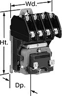
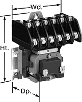
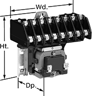
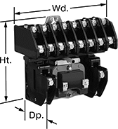
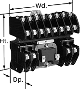
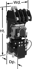
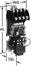
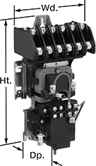
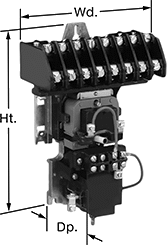
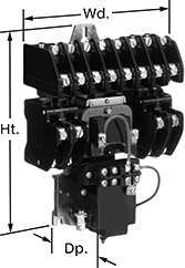
High-Current Lighting Relays
Switch lighting systems on and off—these relays can handle the high switching current on large overhead light systems. They control multiple circuits, so you can manage several lights across your facility with just one relay. For example, use them to switch overhead lights along with lighted signs in different parts of your warehouse. These relays come set for normally-open switching, but you can change them to normally-closed by turning the contacts around with a screwdriver.
Electrically held relays can handle switching on and off frequently. However, because they need constant input voltage to keep the relay switched, they make a humming noise when switched on.
Mechanically held relays are ideal for applications that don’t need to be switched very often, such as lights that stay on all day. Since they switch on and off with a quick burst of input voltage rather than needing constant power, they’re more energy efficient than electrically held relays.
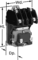
| Number of Terminals | Input Voltage | Control Power | Switching Current @ Voltage (Light Technology) | Max. Switching Voltage | Mechanical Life Cycles | Ht. | Wd. | Dp. | Each | |
2 Circuits Controlled with 2 Off (Normally Open)—DPST-NO | ||||||||||
|---|---|---|---|---|---|---|---|---|---|---|
| 6 | 120V AC | 30VA | 30 A @ 120 V AC (Fluorescent) 20 A @ 120 V AC (Tungsten) | 132V AC | 4,000,000 | 5" | 2.9" | 3.1" | 0000000 | 0000000 |
4 Circuits Controlled with 4 Off (Normally Open)—4PST-NO | ||||||||||
| 10 | 120V AC | 30VA | 30 A @ 120 V AC (Fluorescent) 20 A @ 120 V AC (Tungsten) | 132V AC | 4,000,000 | 5" | 2.9" | 3.1" | 0000000 | 000000 |
| 10 | 277V AC | 30VA | 30 A @ 277 V AC (Fluorescent) 20 A @ 277 V AC (Tungsten) | 300V AC | 4,000,000 | 5" | 2.9" | 3.1" | 0000000 | 000000 |
6 Circuits Controlled with 6 Off (Normally Open)—6PST-NO | ||||||||||
| 14 | 120V AC | 30VA | 30 A @ 120 V AC (Fluorescent) 20 A @ 120 V AC (Tungsten) | 132V AC | 4,000,000 | 5" | 4.3" | 3.1" | 0000000 | 000000 |
| 14 | 277V AC | 30VA | 30 A @ 277 V AC (Fluorescent) 20 A @ 277 V AC (Tungsten) | 300V AC | 4,000,000 | 5" | 4.3" | 3.1" | 0000000 | 000000 |
8 Circuits Controlled with 8 Off (Normally Open)—8PST-NO | ||||||||||
| 18 | 120V AC | 35VA | 30 A @ 120 V AC (Fluorescent) 20 A @ 120 V AC (Tungsten) | 132V AC | 4,000,000 | 5" | 5.6" | 3.1" | 0000000 | 000000 |
10 Circuits Controlled with 10 Off (Normally Open)—10PST-NO | ||||||||||
| 22 | 120V AC | 35VA | 30 A @ 120 V AC (Fluorescent) 20 A @ 120 V AC (Tungsten) | 132V AC | 4,000,000 | 5" | 5.6" | 3.1" | 0000000 | 00000000 |
12 Circuits Controlled with 12 Off (Normally Open)—12PST-NO | ||||||||||
| 26 | 120V AC | 35VA | 30 A @ 120 V AC (Fluorescent) 20 A @ 120 V AC (Tungsten) | 132V AC | 4,000,000 | 5" | 5.6" | 3.1" | 0000000 | 00000000 |
| Number of Terminals | Input Voltage | Control Power | Switching Current @ Voltage (Light Technology) | Max. Switching Voltage | Mechanical Life Cycles | Ht. | Wd. | Dp. | Each | |
2 Circuits Controlled with 2 Off (Normally Open)—DPST-NO | ||||||||||
|---|---|---|---|---|---|---|---|---|---|---|
| 6 | 120V AC | 30VA | 30 A @ 120 V AC (Fluorescent) 20 A @ 120 V AC (Tungsten) | 132V AC | 1,000,000 | 8.8" | 2.9" | 3.3" | 0000000 | 0000000 |
4 Circuits Controlled with 4 Off (Normally Open)—4PST-NO | ||||||||||
| 10 | 120V AC | 30VA | 30 A @ 120 V AC (Fluorescent) 20 A @ 120 V AC (Tungsten) | 132V AC | 1,000,000 | 8.8" | 2.9" | 3.3" | 0000000 | 000000 |
6 Circuits Controlled with 6 Off (Normally Open)—6PST-NO | ||||||||||
| 14 | 120V AC | 30VA | 30 A @ 120 V AC (Fluorescent) 20 A @ 120 V AC (Tungsten) | 132V AC | 1,000,000 | 8.8" | 4.3" | 3.3" | 0000000 | 000000 |
8 Circuits Controlled with 8 Off (Normally Open)—8PST-NO | ||||||||||
| 18 | 120V AC | 35VA | 30 A @ 120 V AC (Fluorescent) 20 A @ 120 V AC (Tungsten) | 132V AC | 1,000,000 | 8.8" | 5.6" | 3.3" | 0000000 | 00000000 |
12 Circuits Controlled with 12 Off (Normally Open)—12PST-NO | ||||||||||
| 26 | 120V AC | 35VA | 30 A @ 120 V AC (Fluorescent) 20 A @ 120 V AC (Tungsten) | 132V AC | 1,000,000 | 8.8" | 5.6" | 3.3" | 0000000 | 00000000 |
Dual-Operator Safety Switches
To prevent accidents, these switches won’t let your machine start running unless two people in different locations coordinate control. This is useful for large operations where it would be difficult to hear or see someone call for power to be cut. They come with two foot switches that communicate wirelessly—both need to be pressed at the same time for your machine to run. For example, if used with a machine that pulls wire up a building through conduit, this means that two people dozens of floors apart can each stop the machine by releasing their foot. As an extra precaution, give the included pendant switches to people walking around your operation. If they see a problem, the pendant switches shut power off with a push of a button, even if the foot switches are pressed.
The foot switches work up to 3.7 miles away from each other if there’s a clear line of sight between the two. If there are walls or other obstacles, they work up to 1,500 ft. away from each other. Plug your equipment into the receiver foot switch before plugging the switch into an outlet—no wiring is required.
| No. of Circuits Controlled | Switch Starting Position | Switch Action | Industry Designation | Switching Current @ Voltage | Max. Transmission Distance, mi | Ht. | Wd. | Dp. | Environmental Rating | Includes | Each | |
Aluminum Housing with Amperage Draw Gauge and LED Status Indicator | ||||||||||||
|---|---|---|---|---|---|---|---|---|---|---|---|---|
NEMA 5-20 Plug × NEMA 5-20 Socket | ||||||||||||
| 1 | 1 Off (Normally Open) | Springs Back (Momentary) | SPST-NO | 20 A @ 120 V AC | 3.7 | 4 1/4" | 6 1/4" | 12 1/4" | IP55 | Receiver Foot Switch, Transmitter Foot Switch, Two Wireless Pendant Switches, Carrying Case, NEMA 5-15 Plug Adapter, Turn-Lock Plug Adapter, Two Battery Chargers | 0000000 | 000000000 |