


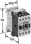
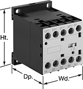
DIN-Rail Mount Touch-Safe Screw Terminal Relays
Quickly and safely mount these relays on 35 mm DIN rail (also known as DIN 3). IP20 rated, they have recessed terminals that prevent fingers and other objects from touching live circuits.
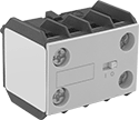
Relays that control 3 and 4 circuits are built to IEC dimensional standards and are often called IEC contactors. Auxiliary contacts (sold separately) allow you to add a signaling device or control another relay. You can add one auxiliary contact to all of these relays. For relays with 12 terminals, you can add two side-mount auxiliary contacts.
Use replacement coils to swap out a broken coil or change the input voltage of a relay. They are only compatible with relays that have 12 terminals. The full load current of the relay must match the full load current range of the coil.
Control | |||||||||
|---|---|---|---|---|---|---|---|---|---|
| Number of Terminals | Input Voltage | Current, mA | Switching Current @ Voltage (Load Type) | Max. Switching Voltage | Ht. | Wd. | Dp. | Each | |
4 Circuits Controlled with 3 Off (Normally Open) and 1 On (Normally Closed)—4PST-3NO/1NC | |||||||||
| 10 | 24V DC | 133 | 10 A @ 600 V AC | 600 V AC | 2.3" | 1.7" | 2.2" | 0000000 | 0000000 |

| Number of Circuits Controlled | For Relay Width | Switch Starting Position | Industry Designation | Mounting Location | Each | |
| 2 | 1.7" | 1 Off (Normally Open) and 1 On (Normally Closed) | DPST-1NO/1NC | Front | 00000000 | 000000 |
Screw Terminal Relays
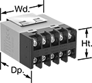
Use the screw terminals to hardwire these relays. The built-in enclosure protects contacts from dust and dirt. These relays accept voltage drops up to 50% of the rated voltage without switching. They’re often used with industrial automation systems, security and emergency lighting, and small motors. Also known as power relays.
Switching Current @ Voltage | |||||||||||
|---|---|---|---|---|---|---|---|---|---|---|---|
| Number of Terminals | Input Voltage | Control Current, mA | Off (Normally Open) Circuit Position | On (Normally Closed) Circuit Position | Maximum Switching Voltage | hp @ Switching Voltage | Ht. | Wd. | Dp. | Each | |
4 Circuits Controlled with 3 Off (Normally Open) and 1 On (Normally Closed)—4PST-3NO/1NC | |||||||||||
| 10 | 120V AC | 22 | 25 A @ 240 V AC/24 V DC | 8 A @ 240 V AC/24 V DC | 250V AC | 1 1/2 hp @ 120 V AC 3 hp @ 240 V AC 3 hp @ 277 V AC | 1.4" | 2" | 2.5" | 0000000 | 000000 |
| 10 | 24V DC | 83 | 25 A @ 240 V AC/24 V DC | 8 A @ 240 V AC/24 V DC | 250V AC | 1 1/2 hp @ 120 V AC 3 hp @ 240 V AC 3 hp @ 277 V AC | 1.4" | 2" | 2.5" | 0000000 | 00000 |
Circuit Board Safety Relays
Reduce connection errors on circuit boards that control machine guards and other safety devices. Also known as force-guided contact relays, they have contact pairs that won’t close at the same time, even if contacts stick or weld shut. These relays take up less space on a board than those with electrical wiring because their solder pin terminals mount directly through circuit board holes. Use them to control high-power components, such as fans and heaters, from a low-power circuit.
Relays with surge suppression coverage protect sensitive electronics from damage and malfunction by eliminating voltage spikes. Switching off a relay can generate surges of 300 to 500 volts, but a diode within these relays suppresses these surges. An LED indicator on these relays lights up when they’re on, so you know at a glance if they’re wired correctly.
![]() For technical drawings and 3-D models, click on a part number.
For technical drawings and 3-D models, click on a part number.
| Number of Terminals | Input Voltage | Control Current, mA | Switching Current @ Voltage | Max. Switching Voltage | Mechanical Life Cycles | Ht. | Wd. | Dp. | Pin Lg. | Features | Surge Suppression Coverage | Each | |
4 Circuits Controlled with 3 Off (Normally Open) and 1 On (Normally Closed)—4PST-3NO/1NC | |||||||||||||
|---|---|---|---|---|---|---|---|---|---|---|---|---|---|
| 10 | 12V DC | 30 | 6 A @ 240 V AC/30 V DC | 250V AC, 125V DC | 10,000,000 | 0.9" | 0.5" | 1.6" | 0.14" | Interlocked Opposing Contacts | __ | 0000000 | 000000 |
| 10 | 12V DC | 32 | 6 A @ 240 V AC/30 V DC | 250V AC, 125V DC | 10,000,000 | 0.9" | 0.5" | 1.6" | 0.14" | Interlocked Opposing Contacts, LED Indicator | Full | 0000000 | 00000 |
| 10 | 24V DC | 15 | 6 A @ 240 V AC/30 V DC | 250V AC, 125V DC | 10,000,000 | 0.9" | 0.5" | 1.6" | 0.14" | Interlocked Opposing Contacts | __ | 0000000 | 00000 |
| 10 | 24V DC | 17 | 6 A @ 240 V AC/30 V DC | 250V AC, 125V DC | 10,000,000 | 0.9" | 0.5" | 1.6" | 0.14" | Interlocked Opposing Contacts, LED Indicator | Full | 0000000 | 00000 |
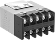
Machine-Guard Relays
The interlocked opposing contacts won't close at the same time, so these relays are suitable for safety applications such as machine guarding. The screw terminals are recessed to prevent accidental contact with live connections. Mount them on 35 mm DIN rail (also known as DIN 3 rail) or flat surfaces. These relays are built to IEC dimensional standards.
Auxiliary contact (sold separately) allows you to add a signaling device or control another relay.
| Number of Terminals | Input Voltage | Control Current, mA | Switching Current @ 600V AC | Max. Switching Voltage | Ht. | Wd. | Dp. | Each | |
4 Circuits Controlled with 3 Off (Normally Open) and 1 On (Normally Closed)—4PST-3NO/1NC | |||||||||
|---|---|---|---|---|---|---|---|---|---|
| 10 | 24V AC | 125 | 10A | 600V AC | 2.3" | 1.7" | 2.2" | 00000000 | 000000 |
| 10 | 120V AC | 25 | 10A | 600V AC | 2.3" | 1.7" | 2.2" | 00000000 | 00000 |
| 10 | 240V AC | 12.5 | 10A | 600V AC | 2.3" | 1.7" | 2.2" | 00000000 | 00000 |
| Number of Circuits Controlled | Switch Starting Position | Industry Designation | Mounting Location | For Relay Width | Each | |
| 2 | 1 Off (Normally Open) and 1 On (Normally Closed) | DPST-1NO/1NC | Front | 1.7" | 00000000 | 000000 |
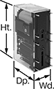
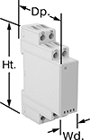
Safety Relays
Receive signals from safety monitoring relays or controllers to switch devices off and on because of a system failure. Also known as force-guided or mechanically linked contacts, the interlocking opposing contacts on these relays cannot be open or closed at the same time. To keep your system from receiving false switching signals, the interlocking opposing contact must remain open even if a contact welds closed.
IP20 rated, they have recessed terminals that prevent fingers and other objects from touching live circuits. These relays have been tested to safety standards that can help you achieve your system's PL (performance level) and SIL (safety integrity level). Choose a relay with a PL and SIL rating to meet the needs of your system. Higher ratings indicate greater safety protection. As your system becomes more complex, you generally require a higher safety protection level. Mount them to 35mm DIN rail (also known as DIN 3 Rail).
Relays that meet SIL2 are tested for applications with a probability of failure of 0.1% to 1%. They’re often used for emergency shutdowns, and fire, gas, and overpressure detection.
![]() For technical drawings and 3-D models, click on a part number.
For technical drawings and 3-D models, click on a part number.
| Number of Terminals | Input Voltage | Control Current, mA | Switching Current @ Voltage | Max. Switching Voltage | Ht. | Wd. | Dp. | Features | Each | |
With Screw Terminals—DIN-Rail Mount | ||||||||||
|---|---|---|---|---|---|---|---|---|---|---|
4 Circuits Controlled with 3 Off (Normally Open) and 1 On (Normally Closed)—4PST-3NO/1NC | ||||||||||
| 12 | 120V AC | 10 | 6 A @ 240 V AC | 250V AC | 3.4" | 0.9" | 3.9" | Interlocked Opposing Contacts, Recessed Terminals, LED Indicator | 00000000 | 0000000 |
| 12 | 24V DC | 42 | 6 A @ 240 V AC | 250V AC | 3.4" | 0.9" | 3.9" | Interlocked Opposing Contacts, Recessed Terminals, LED Indicator | 00000000 | 000000 |