


How to Prime Your Pump
More
How to Determine Feet of Head
More
About Vacuum Pumps
More
About Process Pumps
More
About Drum Pumps
More
Low-Maintenance Plastic Circulation Pumps for Water and Coolants
Eliminate seal wear and leakage with pumps that use magnets to turn the impeller. They’re often used with electroplating and photographic solutions. Pumps are gravity fed and require an elevated liquid source to fully fill the pump before turning on. Do not run dry or use with solids.
Note: If flow control is needed, place valves or reducers on the discharge side; never restrict the inlet of a pump with a valve or reducer.

Flow Rate, gpm | Intake | Discharge | Overall | ||||||||||||||||
|---|---|---|---|---|---|---|---|---|---|---|---|---|---|---|---|---|---|---|---|
| Max. Flow Rate, gpm | @ 10 ft. of Head | @ 20 ft. of Head | Max. ft. of Head | Max. Pressure, psi | Max. Viscosity, cP | Temp. Range, °F | hp | Current, A | Pipe Size | Gender | Thread Type | Pipe Size | Gender | Thread Type | Lg. | Wd. | Ht. | Each | |
120V AC, Single Phase—With Thermal Overload Protection | |||||||||||||||||||
Plug | |||||||||||||||||||
| 15 | 12 | 8 | 34.6 | 15 | 20 | 35° to 150° | 1/8 | 2.1 | 1/2 | Female | NPT | 1/2 | Male | NPT | 8 3/8" | 5 1/2" | 5 5/8" | 0000000 | 0000000 |
| 17 | 13 | 8 | 27.5 | 11 | 20 | 35° to 150° | 1/8 | 2 | 1 | Female | NPT | 1/2 | Male | NPT | 8 3/4" | 5 1/2" | 5 1/2" | 0000000 | 000000 |
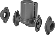
Harsh-Environment Low-Maintenance Plastic
Circulation Pumps for Water and Coolants

These pumps have a totally enclosed fan-cooled (TEFC) motor for use in dusty, dirty, and damp environments. The impeller is turned with magnets to eliminate seal wear and leakage for a long service life. Pumps are often used with electroplating and photographic solutions. They are gravity fed and require an elevated liquid source to fully fill the pump before turning on. Do not run dry or use with solids.
Note: If flow control is needed, place valves or reducers on the discharge side; never restrict the inlet of a pump with a valve or reducer.
![]() For technical drawings and 3-D models, click on a part number.
For technical drawings and 3-D models, click on a part number.
Flow Rate, gpm | Intake (NPT) | Discharge (NPT) | Overall | |||||||||||||
|---|---|---|---|---|---|---|---|---|---|---|---|---|---|---|---|---|
| Max. Flow Rate, gpm | @ 10 ft. of Head | @ 20 ft. of Head | Max. ft. of Head | Max. Pressure, psi | Max. Viscosity, cP | hp | Current, A | Pipe Size | Gender | Pipe Size | Gender | Lg. | Wd. | Ht. | Each | |
120/240V AC, Single Phase—With Thermal Overload Protection | ||||||||||||||||
Plug | ||||||||||||||||
| 20 | 17 | 11 | 29.3 | 10 | 20 | 1/8 | 3/1.4 | 1 | Female | 1/2 | Male | 11 1/4" | 5 1/4" | 7 3/8" | 0000000 | 0000000 |
Adjustable-Flow Inline Circulation Pumps for Water

Accommodate performance changes in your system with a three-speed switch that adjusts flow rate. Install these pumps directly in your pipeline for applications such as hot-water circulation and hydronic heating and cooling. They have an open dripproof (ODP) motor for use in clean, dry, and well-ventilated environments. Mount horizontally with the included pipe connectors. Do not run dry or use with solids. Note: If flow control is needed, place valves or reducers on the discharge side; never restrict the inlet of a pump with a valve or reducer.
Pumps with 304 stainless steel housing are lead free.
Flow Rate, gpm (Speed No.) | Pipe Size (Female, NPT) | Overall | |||||||||||
|---|---|---|---|---|---|---|---|---|---|---|---|---|---|
| Max. | @ 10 ft. of Head | Current, A (Speed No.) | Flow Adjustment Rate | Max. ft. of Head | Max. Viscosity, cP | hp | Intake | Discharge | Lg. | Wd. | Ht. | Each | |
120V AC, Single Phase—Without Thermal Overload Protection | |||||||||||||
Cast Iron Housing—Hardwire | |||||||||||||
| 7 (1), 13 (2), 18 (3) | 2 (1), 6 (2), 9 (3) | 0.5 (1), 0.6 (2), 0.8 (3) | ± 10% | 18 | 1 | 1/8 | 1 | 1 | 6" | 5" | 6 3/8" | 0000000 | 0000000 |
| 7 (1), 13 (2), 18 (3) | 2 (1), 6 (2), 9 (3) | 0.5 (1), 0.6 (2), 0.8 (3) | ± 10% | 18 | 1 | 1/8 | 1 1/4 | 1 1/4 | 6" | 5" | 6 3/8" | 00000000 | 000000 |
| 7 (1), 13 (2), 18 (3) | 2 (1), 6 (2), 9 (3) | 0.5 (1), 0.6 (2), 0.8 (3) | ± 10% | 18 | 1 | 1/8 | 1 1/2 | 1 1/2 | 6" | 5" | 6 3/8" | 0000000 | 000000 |
304 Stainless Steel Housing—Hardwire | |||||||||||||
| 7 (1), 13 (2), 18 (3) | 2 (1), 6 (2), 9 (3) | 0.5 (1), 0.6 (2), 0.8 (3) | ± 10% | 18 | 1 | 1/8 | 1 | 1 | 6" | 5" | 6 3/8" | 00000000 | 000000 |
| 7 (1), 13 (2), 18 (3) | 2 (1), 6 (2), 9 (3) | 0.5 (1), 0.6 (2), 0.8 (3) | ± 10% | 18 | 1 | 1/8 | 1 1/4 | 1 1/4 | 6" | 5" | 6 3/8" | 00000000 | 000000 |
| 7 (1), 13 (2), 18 (3) | 2 (1), 6 (2), 9 (3) | 0.5 (1), 0.6 (2), 0.8 (3) | ± 10% | 18 | 1 | 1/8 | 1 1/2 | 1 1/2 | 6" | 5" | 6 3/8" | 00000000 | 000000 |
Compact Inline Circulation Pumps for Water
Use these pumps in pipelines with limited clearance. Install directly in your pipeline for applications such as hot-water circulation and hydronic heating and cooling. Pumps mount horizontally or vertically with required pipe connectors. The motor cannot face downward; it’s cooled by the water being pumped. Do not run dry or use with solids.
Note: If flow control is needed, place valves or reducers on the discharge side; never restrict the inlet of a pump with a valve or reducer.
Flow Rate, gpm | Intake | Discharge | Overall | Mounting | ||||||||||||||||
|---|---|---|---|---|---|---|---|---|---|---|---|---|---|---|---|---|---|---|---|---|
| Max. Flow Rate, gpm | @ 10 ft. of Head | @ 20 ft. of Head | @ 30 ft. of Head | Max. ft. of Head | Max. Viscosity, cP | hp | Current, A | Pipe Size | Gender | Thread Type | Pipe Size | Gender | Thread Type | Lg. | Wd. | Ht. | No. of Holes | Hole Dia. | Each | |
120V AC, Single Phase | ||||||||||||||||||||
Hardwire | ||||||||||||||||||||
| 31 | 22 | 13 | 5 | 32 | 1 | 1/8 | 1.76 | 3/4 | Female | NPT | 3/4 | Female | NPT | 7 5/8" | 6 1/2" | 6" | 2 | 1/2" | 00000000 | 0000000 |
| 31 | 22 | 13 | 5 | 32 | 1 | 1/8 | 1.76 | 1 | Female | NPT | 1 | Female | NPT | 7 5/8" | 6 1/2" | 6" | 2 | 1/2" | 0000000 | 000000 |
| 31 | 22 | 13 | 5 | 32 | 1 | 1/8 | 1.76 | 1 1/4 | Female | NPT | 1 1/4 | Female | NPT | 7 5/8" | 6 1/2" | 6" | 2 | 1/2" | 00000000 | 000000 |
| 31 | 22 | 13 | 5 | 32 | 1 | 1/8 | 1.76 | 1 1/2 | Female | NPT | 1 1/2 | Female | NPT | 7 5/8" | 6 1/2" | 6" | 2 | 1/2" | 0000000 | 000000 |
Immersion Circulation Pumps for Coolants

Commonly used in machine tool coolant tanks, these pumps have an intake that can be completely submerged in liquid. A universal mounting plate fits machine tools from manufacturers such as Fuji, Mitsubishi, Toshiba, Hitachi, and Yasukawa. Motor is totally enclosed with sealed bearings for use in dusty, dirty, and damp environments. Pumps are gravity fed and require an elevated liquid source. They can run dry.
Note: If flow control is needed, place valves or reducers on the discharge side; never restrict the inlet of a pump with a valve or reducer.
Pumps | |||||||||||||||||
|---|---|---|---|---|---|---|---|---|---|---|---|---|---|---|---|---|---|
Flow Rate, gpm | Discharge (NPT) | Overall | Replacement Impellers | ||||||||||||||
| Max. Flow Rate, gpm | @ 10 ft. of Head | Max. ft. of Head | Max. Pressure, psi | Max. Viscosity, cP | hp | Current, A | Intake Connection Type | Pipe Size | Gender | Lg. | Wd. | Ht. | Shaft Ht. | Each | Each | ||
120/240V AC, Single Phase—Without Thermal Overload Protection | |||||||||||||||||
Hardwire | |||||||||||||||||
| 10 | 5 | 13 | 5 | 90 | 1/8 | 0.7/0.4 | Open Inlet | 3/8 | Female | 5 1/2" | 3 1/2" | 11 3/4" | 6" | 00000000 | 0000000 | 0000000 | 000000 |
240/460V AC, Three Phase—Without Thermal Overload Protection | |||||||||||||||||
Hardwire | |||||||||||||||||
| 10 | 5 | 13 | 5 | 90 | 1/8 | 0.3/0.2 | Open Inlet | 3/8 | Female | 5 1/2" | 3 1/2" | 11 3/4" | 6" | 00000000 | 000000 | 0000000 | 00000 |
Remote-Mount Circulation Pumps for Water and Coolants

Use when space is limited—these pumps connect to a pipe coming from your tank so you can place the pump in another location. Mount above or below the liquid level. Pumps are self-priming after you fill the pump chamber with liquid. As liquid in the chamber is expelled, a suction force is created which allows the pump to draw liquid upward.
Note: Pumps must be filled with liquid before use. They need a constant flow of liquid and cannot run dry. If flow control is needed, place valves or reducers on the discharge side; never restrict the inlet of a pump with a valve or reducer.
Pumps | |||||||||||||||||
|---|---|---|---|---|---|---|---|---|---|---|---|---|---|---|---|---|---|
Flow Rate, gpm | Intake (NPT) | Discharge (NPT) | Overall | Replacement Impellers | |||||||||||||
| Max. Flow Rate, gpm | @ 10 ft. of Head | Max. ft. of Head | Max. Pressure, psi | Max. Viscosity, cP | hp | Current, A | Pipe Size | Gender | Pipe Size | Gender | Lg. | Wd. | Ht. | Each | Each | ||
120/240V AC, Single Phase—Without Thermal Overload Protection | |||||||||||||||||
Hardwire | |||||||||||||||||
| 10 | 5 | 13 | 5 | 90 | 1/8 | 0.7/0.4 | 3/8 | Female | 3/8 | Female | 6 1/2" | 5 1/2" | 6 7/8" | 00000000 | 0000000 | 0000000 | 000000 |
240/460V AC, Three Phase—Without Thermal Overload Protection | |||||||||||||||||
Hardwire | |||||||||||||||||
| 10 | 5 | 13 | 5 | 90 | 1/8 | 0.3/0.2 | 3/8 | Female | 3/8 | Female | 6 1/2" | 5 1/2" | 6 7/8" | 00000000 | 000000 | 0000000 | 00000 |
| Maintenance Kit for Pumps with 10 gpm or 20 gpm Max. Flow Rate | 00000000 | Each | 000000 |
Electric Drum Pumps with Nozzle for Fuel

Pump fuel in hazardous environments with flammable gases. Pumps are UL listed for Class I, Divisions 1 and 2, Group D.
Always bond and ground your application for static control. For more information about bonding and grounding, see Sections 1910.106 and 1910.107 of the Federal OSHA Code or see bonding and grounding equipment.
Style A pumps have a circuit breaker to prevent overload. Pumps with automatic shut-off nozzle turn off when the tank is full.
Temp. Range, °F | Intake | Discharge | |||||||||||||||
|---|---|---|---|---|---|---|---|---|---|---|---|---|---|---|---|---|---|
| Flow Rate, gpm | Discharge Pressure, psi | Max. Viscosity, cP | Min. | Max. | Horsepower | Current, A | Max. Lift, ft. | For Drum Opening Size | Tube OD | Tube Lg. | Hose ID | Hose Lg., ft. | Hose OD | Nozzle Type | Electrical Connection Type | Each | |
120V AC, Single Phase—With Thermal Overload Protection | |||||||||||||||||
| 12 | 15 | 10 | -20° | 125 | 1/8 hp | 1.5 | 4.8 | 2 NPT | 1 7/16" | 22"-40" | 3/4" | 12 | 1 5/32" | Automatic Shut-Off | Hardwire | 0000000 | 0000000 |
| 12 | 15 | 10 | -20° | 125 | 1/8 hp | 1.5 | 5.5 | 2 NPT | 1 7/16" | 22"-40" | 3/4" | 12 | 1 5/32" | Manual Shut-Off | Hardwire | 0000000 | 000000 |
Portable Oil-Free Electric Vacuum Pumps
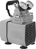
These pumps weigh only 16 pounds and have a handle, so they're convenient for on-site sampling, atomizing, and vacuum filtration. They're also for use in pressure applications up to 60 psi. Since they don't require lubrication, there’s no risk of oil contamination. Maximum flow rate is the rate at which air is pumped before a vacuum is created. Flow rate steadily decreases as the pump generates the vacuum. The larger the tank, the longer it will take to form a vacuum. Tube and fitting ID will also affect flow.
Repair kits include filter/muffler components, a gasket, a leaf valve, limiters, and an O-ring.
Pumps | |||||||||||||||||
|---|---|---|---|---|---|---|---|---|---|---|---|---|---|---|---|---|---|
Intake | Discharge | Overall | Repair Kits | ||||||||||||||
| Max. Vacuum, in. of Hg | Max. Flow Rate, cfm | Max. Pressure, psi | Temp. Range, °F | Volume, dBA | Horsepower | Current, A | Tube Connection Type | For Tube ID | Tube Connection Type | For Tube ID | Lg. | Wd. | Ht. | Each | Each | ||
120V AC, Single Phase—With Thermal Overload Protection | |||||||||||||||||
NEMA 5-15 Plug | |||||||||||||||||
| 25.5 | 1.1 | 60 | 35° to 100° | 65 | 1/8 hp | 4.2 | Barbed | 3/8" | Barbed | 3/8" | 7 3/4" | 5 7/8" | 11" | 0000000 | 0000000 | 0000000 | 000000 |
Flood Coolant Dispensers with Reservoir

These dispensers have a reservoir for recirculating coolant. They provide a constant flow of coolant, so they dissipate heat more efficiently than mist and droplet dispensers, making them suitable for cooling long machine cycles. Coolant strainers prevent debris from getting into the recirculated coolant.
Maximum flow rate and shut-off height are for water-soluble oil. Shut-off height is the maximum height to which the water-soluble oil can be pumped.
Nozzle | Reservoir | ||||||||||||||||
|---|---|---|---|---|---|---|---|---|---|---|---|---|---|---|---|---|---|
| Cap., gal. | Max. Flow Rate | Max. Pressure, psi | Coolant Outlet Hose Lg. | Lg. | Type | Nozzle Material | O'all Ht. | Wd. | Dp. | Reservoir Material | Shut-Off Ht., ft. | For Max. SSU Viscosity Grade | Voltage | Features | Each | ||
For Use With Coolant, Water | |||||||||||||||||
| C | 6 | 600 gph @ 1 ft. of head | 5.6 | 4 ft. | 15" | Flexible | Steel | 15" | 18" | 9 1/2" | Steel | 14 | 500 | 120V AC | Adjustable Flow, Coolant Strainer, Baffle, On/Off Valve | 0000000 | 0000000 |
| C | 10 | 600 gph @ 1 ft. of head | 5.6 | 4 ft. | 15" | Flexible | Steel | 16 1/2" | 24" | 9 3/4" | Steel | 14 | 500 | 120V AC | Adjustable Flow, Coolant Strainer, On/Off Valve | 0000000 | 000000 |