


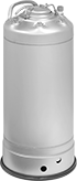
Pressurized Liquid Dispensing Tanks
Attach a compressed air source to pressurize liquids for dispensing and spraying. Tanks have a dip tube that draws liquid from the bottom of the tank. All tanks meet the ASME rating for pressure vessels.
304 stainless steel tanks have good corrosion resistance.
316 stainless steel tanks have excellent corrosion resistance.
Tanks that cannot be sold to the listed areas are restricted due to safety regulations.
![]() For technical drawings and 3-D models, click on a part number.
For technical drawings and 3-D models, click on a part number.
Overall | Opening | Port | ||||||||||||
|---|---|---|---|---|---|---|---|---|---|---|---|---|---|---|
| Capacity, gal. | Max. Pressure @ 100°F, psi | Dia. | Ht. | Lg. | Wd. | Pipe Size | Thread Type | Gender | No. of | Temp. Range, °F | Specifications Met | Cannot Be Sold To | Each | |
Tanks without Mounting Plate | ||||||||||||||
304 Stainless Steel | ||||||||||||||
| 1 | 142 | 9" | 9" | 4 7/8" | 5 7/8" | 1/4 | NPT | Female | 4 | -20° to 200° | ASME BPVC.VIII.1 | Canada | 00000000 | 0000000 |
| 1 | 205 | 9" | 8" | 3 1/4" | 3 7/8" | 1/4 | NPT | Female | 4 | -20° to 200° | ASME BPVC.VIII.1 | Canada | 00000000 | 000000 |
| 2 | 142 | 9" | 12" | 4 7/8" | 5 7/8" | 1/4 | NPT | Female | 4 | -20° to 200° | ASME BPVC.VIII.1 | Canada | 00000000 | 000000 |
| 2 | 205 | 9" | 11 1/2" | 3 1/4" | 3 7/8" | 1/4 | NPT | Female | 4 | -20° to 200° | ASME BPVC.VIII.1 | Canada | 00000000 | 000000 |
| 3 | 142 | 9" | 15" | 4 7/8" | 5 7/8" | 1/4 | NPT | Female | 4 | -20° to 200° | ASME BPVC.VIII.1 | Canada | 00000000 | 000000 |
| 3 | 205 | 9" | 15" | 3 1/4" | 3 7/8" | 1/4 | NPT | Female | 4 | -20° to 200° | ASME BPVC.VIII.1 | Canada | 00000000 | 000000 |
| 5 | 142 | 9" | 23" | 4 7/8" | 5 7/8" | 1/4 | NPT | Female | 4 | -20° to 200° | ASME BPVC.VIII.1 | Canada | 00000000 | 000000 |
| 5 | 205 | 9" | 22" | 3 1/4" | 3 7/8" | 1/4 | NPT | Female | 4 | -20° to 200° | ASME BPVC.VIII.1 | Canada | 00000000 | 000000 |
| 10 | 129 | 12" | 25" | 4 7/8" | 5 7/8" | 1/4 | NPT | Female | 4 | -20° to 200° | ASME BPVC.VIII.1 | Canada | 00000000 | 00000000 |
| 10 | 165 | 12" | 25" | 3 1/4" | 3 7/8" | 1/4 | NPT | Female | 4 | -20° to 200° | ASME BPVC.VIII.1 | Canada | 00000000 | 00000000 |
| 16 | 129 | 12" | 37" | 4 7/8" | 5 7/8" | 1/4 | NPT | Female | 4 | -20° to 200° | ASME BPVC.VIII.1 | Canada | 00000000 | 00000000 |
| 16 | 165 | 12" | 38" | 3 1/4" | 3 7/8" | 1/4 | NPT | Female | 4 | -20° to 200° | ASME BPVC.VIII.1 | Canada | 00000000 | 00000000 |
| 25 | 130 | 18" | 28" | 4 7/8" | 5 7/8" | 1/4 | NPT | Female | 4 | -20° to 200° | ASME BPVC.VIII.1 | Canada | 00000000 | 00000000 |
316 Stainless Steel | ||||||||||||||
| 1 | 132 | 9" | 8" | 4 7/8" | 5 7/8" | 1/4 | NPT | Female | 4 | -20° to 300° | ASME BPVC.VIII.1 | Canada | 00000000 | 000000 |
| 1 | 185 | 9" | 8" | 3 1/4" | 3 7/8" | 1/4 | NPT | Female | 4 | -20° to 300° | ASME BPVC.VIII.1 | Canada | 0000000 | 000000 |
| 2 | 132 | 9" | 12" | 4 7/8" | 5 7/8" | 1/4 | NPT | Female | 4 | -20° to 300° | ASME BPVC.VIII.1 | Canada | 00000000 | 000000 |
| 2 | 185 | 9" | 12" | 3 1/4" | 3 7/8" | 1/4 | NPT | Female | 4 | -20° to 300° | ASME BPVC.VIII.1 | Canada | 0000000 | 000000 |
| 3 | 132 | 9" | 15" | 4 7/8" | 5 7/8" | 1/4 | NPT | Female | 4 | -20° to 300° | ASME BPVC.VIII.1 | Canada | 00000000 | 000000 |
| 3 | 185 | 9" | 15" | 3 1/4" | 3 7/8" | 1/4 | NPT | Female | 4 | -20° to 300° | ASME BPVC.VIII.1 | __ | 0000000 | 000000 |
| 5 | 132 | 9" | 22" | 4 7/8" | 5 7/8" | 1/4 | NPT | Female | 4 | -20° to 300° | ASME BPVC.VIII.1 | Canada | 00000000 | 00000000 |
| 5 | 185 | 9" | 22" | 3 1/4" | 3 7/8" | 1/4 | NPT | Female | 4 | -20° to 300° | ASME BPVC.VIII.1 | Canada | 0000000 | 000000 |
| 10 | 115 | 12" | 25" | 4 7/8" | 5 7/8" | 1/4 | NPT | Female | 4 | -20° to 300° | ASME BPVC.VIII.1 | Canada | 00000000 | 00000000 |
| 10 | 190 | 12" | 25" | 3 1/4" | 3 7/8" | 1/4 | NPT | Female | 4 | -20° to 300° | ASME BPVC.VIII.1 | Canada | 0000000 | 00000000 |
| 16 | 115 | 12" | 37" | 4 7/8" | 5 7/8" | 1/4 | NPT | Female | 4 | -20° to 300° | ASME BPVC.VIII.1 | Canada | 00000000 | 00000000 |
| 16 | 190 | 12" | 38" | 3 1/4" | 3 7/8" | 1/4 | NPT | Female | 4 | -20° to 300° | ASME BPVC.VIII.1 | Canada | 0000000 | 00000000 |
| 25 | 129 | 18" | 28" | 4 7/8" | 5 7/8" | 1/4 | NPT | Female | 4 | -20° to 300° | ASME BPVC.VIII.1 | Canada | 00000000 | 00000000 |
Vacuum closure caps are required to use tanks in vacuum applications.
Sanitary Pressurized Liquid Dispensing Tanks
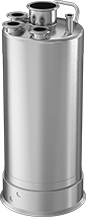
Store and dispense liquids in food, pharmaceutical, and beverage plants—these tanks attach to a compressed air source for use in sanitary environments. A dip tube draws liquid from the bottom of these tanks for dispensing and spraying. They’re made of 316L stainless steel for excellent corrosion resistance, and have an electropolished finish that prevents product buildup and bacterial growth. Connect them to valves, hose, and caps with quick-clamp sanitary tube fittings, which are easier to sanitize than threaded fittings. Tanks comply with ASME BPVC.VIII safety standards for pressure vessels.
Safety regulations restrict sales to the listed jurisdictions/areas.
![]() For technical drawings and 3-D models, click on a part number.
For technical drawings and 3-D models, click on a part number.
Overall | Gauge Port | |||||||||||
|---|---|---|---|---|---|---|---|---|---|---|---|---|
| Capacity, gal. | Maximum Pressure @ 100° F, psi | Diameter | Height | Opening Diameter | Flange OD | Gender | Number of | Temperature Range, °F | Specifications Met | Cannot Be Sold To | Each | |
Tanks without Mounting Plate | ||||||||||||
Electropolished 316L Stainless Steel | ||||||||||||
| 5 | 185 | 9" | 23" | 3" | 1 1/2" | Female | 4 | -20° to 100° | ASME BPVC.VIII.1 | Canada | 0000000 | 000000000 |
| 10 | 125 | 12" | 25" | 3" | 1 1/2" | Female | 4 | -20° to 100° | ASME BPVC.VIII.1 | Canada | 0000000 | 00000000 |
Pressure-Rated Water Tanks
--7b4402cf881609347062-p9@halfx_637449222773319180.png?ver=imagenotfound)
--54972b9c0e11610558274-p9@halfx_637461335915238114.png?ver=imagenotfound)
These tanks can be used as water heaters when used with a heat source, such as an immersion heater. Also known as boiler tanks, they are designed to handle water pressure changes. Use them with hot or cold water. All are galvanized inside and outside for corrosion resistance.
![]() For technical drawings and 3-D models, click on a part number.
For technical drawings and 3-D models, click on a part number.
Tank End Connection Pipe Size | Tank Side Connection Pipe Size | |||||||||||||||||||
|---|---|---|---|---|---|---|---|---|---|---|---|---|---|---|---|---|---|---|---|---|
| Capacity, gal. | Dia. | Overall Lg. | Lg. (A) | Lg. (B) | Lg. (C) | Lg. (D) | (E1) | (E2) | (S1) | (S2) | (S3) | (S4) | (S5) | Pipe Connection Thread Type | Pipe Connection Gender | Wall Gauge, ga. | Max. Temp., °F | Max. Pressure, psi | Each | |
Galvanized Steel | ||||||||||||||||||||
| 15 | 12" | 30" | 18" | 6" | 8" | 6" | 1 | 1 | 1 | 1 | 1 | 1 1/4 | 1/2 | NPT | Female | 14 | 450° | 75 | 0000000 | 0000000 |
| 30 | 12" | 60" | 18" | 6" | 8" | 6" | 1 | 1 | 1 | 1 | 1 | 1 1/4 | 1/2 | NPT | Female | 14 | 450° | 75 | 0000000 | 000000 |
| 40 | 14" | 60" | 18" | 6" | 8" | 6" | 1 | 1 | 1 | 1 | 1 | 1 1/4 | 1/2 | NPT | Female | 14 | 450° | 75 | 0000000 | 000000 |
| 82 | 20" | 60" | 18" | 6" | 8" | 6" | 1 | 1 | 1 | 1 | 1 | 1 1/4 | 1/2 | NPT | Female | 14 | 450° | 75 | 0000000 | 000000 |
ASME-Code Expansion Tanks for Water


--7cc059f10c41610560320-p9@halfx_637461359604633535.png?ver=imagenotfound)
Manufactured in accordance with ASME BPVC.VIII.1, these tanks accommodate the expansion of heated water and provide a cushion of compressed air in closed water-heating systems. They prevent water loss by eliminating the need to expel hot water from systems during each heating cycle.
![]() For technical drawings and 3-D models, click on a part number.
For technical drawings and 3-D models, click on a part number.
Tank End Connection Pipe Size | Tank Side Connection Pipe Size | ||||||||||||||||
|---|---|---|---|---|---|---|---|---|---|---|---|---|---|---|---|---|---|
| Capacity, gal. | Dia. | Overall Lg. | Lg. (A) | Lg. (B) | Lg. (C) | (E1) | (E2) | (S1) | (S2) | Pipe Connection Thread Type | Pipe Connection Gender | Wall Gauge, ga. | Max. Temp., °F | Max. Pressure, psi | Expansion Tank Type | Each | |
Gray-Painted Steel | |||||||||||||||||
| 15 | 12" | 34 1/4" | 7" | 19" | 8" | 1/2 | 1/2 | 1 | 1 | NPT | Female | 13 | 450° | 150 | Bladderless | 00000000 | 0000000 |
| 30 | 14" | 49 9/16" | 8 3/8" | 31 1/4" | 10" | 1/2 | 1/2 | 1 1/2 | 1 1/2 | NPT | Female | 12 | 450° | 150 | Bladderless | 00000000 | 000000 |
| 40 | 14" | 64 5/8" | 8 3/8" | 46 1/4" | 10" | 1/2 | 1/2 | 1 1/2 | 1 1/2 | NPT | Female | 12 | 450° | 150 | Bladderless | 00000000 | 000000 |
| 80 | 20" | 66 1/8" | 10 3/4" | 42" | 16" | 1/2 | 1/2 | 2 | 2 | NPT | Female | 11 | 450° | 150 | Bladderless | 00000000 | 000000 |
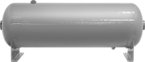
Expansion Tanks for Water
Use these tanks to accommodate the expansion of heated water and provide a cushion of compressed air in closed water-heating systems. They prevent water loss by eliminating the need to expel hot water from systems during each heating cycle.
Galvanized steel tanks are hot-dipped for maximum corrosion resistance.
![]() For technical drawings and 3-D models, click on a part number.
For technical drawings and 3-D models, click on a part number.


--7c3c6a02a0d1610558279-p9@halfx_637461339024669794.png?ver=imagenotfound)
Tank Side Connection Pipe Size | |||||||||||||||
|---|---|---|---|---|---|---|---|---|---|---|---|---|---|---|---|
| Capacity, gal. | Dia. | Overall Lg. | Lg. (A) | Lg. (B) | Tank End Connection Pipe Size (E1) | (S1) | (S2) | Pipe Connection Thread Type | Pipe Connection Gender | Wall Gauge, ga. | Max. Temp., °F | Max. Pressure, psi | Expansion Tank Type | Each | |
| 8 | 9" | 32" | 5" | 11" | 3/4 | 1/2 | 1/2 | NPT | Female | 14 | 450° | 75 | Bladderless | 000000 | 0000000 |
| 15 | 12" | 30" | 4" | 11" | __ | 1/2 | 1/2 | NPT | Female | 14 | 450° | 75 | Bladderless | 000000 | 000000 |
| 18 | 12" | 36" | 4" | 14" | __ | 1/2 | 1/2 | NPT | Female | 14 | 450° | 75 | Bladderless | 000000 | 000000 |

--2f436187df31610558284-p9@halfx_637461338101519682.png?ver=imagenotfound)
-1610456742-p9@halfx_637460319512142470.png?ver=imagenotfound)
Tank End Connection Pipe Size | Tank Side Connection Pipe Size | ||||||||||||||||||
|---|---|---|---|---|---|---|---|---|---|---|---|---|---|---|---|---|---|---|---|
| Capacity, gal. | Dia. | Overall Lg. | Lg. (A) | Lg. (B) | Lg. (C) | (E1) | (E2) | (E3) | (S1) | (S2) | (S3) | Pipe Connection Thread Type | Pipe Connection Gender | Wall Gauge, ga. | Max. Temp., °F | Max. Pressure, psi | Expansion Tank Type | Each | |
| 8 | 12" | 19" | 4" | 4" | 8 13/16" | 1/2 | 1/2 | 2 | 1 1/4 | 1/2 | 1/2 | NPT | Female | 14 | 450° | 75 | Bladderless | 0000000 | 0000000 |
| 15 | 12" | 33" | 4" | 11" | 8 13/16" | 1/2 | 1/2 | 2 | 1 1/4 | 1/2 | 1/2 | NPT | Female | 14 | 450° | 75 | Bladderless | 0000000 | 000000 |
| 40 | 14" | 63" | 4" | 26" | 8 13/16" | 1/2 | 1/2 | 2 | 1 1/4 | 1/2 | 1/2 | NPT | Female | 14 | 450° | 75 | Bladderless | 0000000 | 000000 |
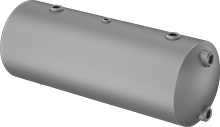
Lightweight Compressed Air Storage Tanks
Tanks have drain ports on the bottom to remove condensation. All other ports can be used as inlets or outlets in any configuration.
They cannot be sold to New Jersey or Canada due to safety and pressure vessel regulations.
![]() For technical drawings and 3-D models, click on a part number.
For technical drawings and 3-D models, click on a part number.
Ports | Overall | |||||||||||
|---|---|---|---|---|---|---|---|---|---|---|---|---|
| Cap., gal. | Max. Pressure, psi | Total No. of | Gender | Sizes | Lg. | Dia. | Ht. | Wall Thick. | Temp. Range, °F | Cannot Be Sold To | Each | |
Horizontal | ||||||||||||
Fiberglass | ||||||||||||
| 2 | 150 | 4 | Female | 1/4 NPT Port (1 ea.) 3/4 NPT Port (2 ea.) 1/8 NPT Drain Port (1 ea.) | 18" | 6 1/4" | 9" | 1/8" | -20° to 150° | Canada, NJ | 000000 | 0000000 |
| 5 | 150 | 4 | Female | 1/4 NPT Port (1 ea.) 3/4 NPT Port (2 ea.) 1/8 NPT Drain Port (1 ea.) | 21 3/8" | 9 1/4" | 12" | 1/8" | -20° to 150° | Canada, NJ | 000000 | 00000000 |
| 7 | 150 | 4 | Female | 1/4 NPT Port (1 ea.) 3/4 NPT Port (2 ea.) 1/8 NPT Drain Port (1 ea.) | 29 3/8" | 9 1/4" | 12" | 1/8" | -20° to 150° | Canada, NJ | 000000 | 00000000 |
| 10 | 150 | 4 | Female | 1/4 NPT Port (1 ea.) 3/4 NPT Port (2 ea.) 1/8 NPT Drain Port (1 ea.) | 40 3/8" | 9 1/4" | 12" | 1/8" | -20° to 150° | Canada, NJ | 000000 | 00000000 |
Syringe Loading Tanks
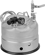
Fill syringes quickly without the mess—these tanks use compressed air to push viscous liquid into a syringe. They hold up to a gallon of material, so you can fill many syringes one after another. To fill a syringe, connect a compressed air source to the tank, twist a syringe onto the dispenser, and slowly turn the ball valve. If you’re using a manually powered syringe, check first to make sure the plunger is fully depressed. For air powered ones, check that the stopper is fully inserted.
Monitor the tank’s pressure with a built-in gauge. An included regulator works to hold the tank pressure around the recommended 100 psi. If the pressure gets too high, pull the tab on the release valve. To prolong the life of the material in your tank, you should release the pressure after filling your last syringe. These tanks cannot be sold to Canada due to safety regulations.
Overall | Inlet | Outlet | ||||||||||||||
|---|---|---|---|---|---|---|---|---|---|---|---|---|---|---|---|---|
| Capacity, gal. | Max. Pressure @ 100° F | Dia. | Ht. | Opening Dia. | No. of Inlets | Coupling Size | Connection Style | Gender | No. of Outlets | Connection Type | Gender | Temp. Range, °F | Features | Cannot Be Sold To | Each | |
304 Stainless Steel | ||||||||||||||||
| 1 | 100 psi | 10" | 11 1/2" | 6" | 1 | 1/8 | Quick Disconnect | Male | 1 | Luer Lock | Female | -20° to 100° | Pressure Gauge, Safety Valve | Canada | 000000 | 000000000 |