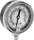
About Precision Flow-Adjustment Valves
More
About Air Preparation
More
About Air Compressors
More
Compressed Air Regulating Manifolds


Use a single air supply to meet the pressure requirements of multiple applications—connect one of these manifolds to your air line, and then set a different output pressure for each station. All are relieving regulators, so they exhaust when the downstream pressure exceeds the set pressure. Install in your air line after filters.
Pipe Size | Overall | ||||||||||
|---|---|---|---|---|---|---|---|---|---|---|---|
| No. of Stations | Inlet | Outlet | Max. Flow Rate | Max. Pressure, psi | Gauge Included | Wd. | Ht. | Max. Temp., °F | Pressure Regulating Range, psi | Each | |
Aluminum Housing—NPT Female Inlet and Outlet | |||||||||||
±1.6% Accuracy | |||||||||||
| 2 | 1/4 | 1/4 | 65 scfm @ 100 psi | 206 | Yes | 3 1/4" | 4 7/8" | 140° | 4.4-176 | 0000000 | 0000000 |
| 2 | 1/2 | 1/2 | 230 scfm @ 100 psi | 290 | Yes | 6 1/4" | 7 3/8" | 140° | 4.4-174 | 0000000 | 000000 |
| 4 | 1/4 | 1/4 | 65 scfm @ 100 psi | 206 | Yes | 6 3/8" | 4 7/8" | 140° | 4.4-176 | 0000000 | 000000 |
| 4 | 1/2 | 1/2 | 230 scfm @ 100 psi | 290 | Yes | 12 3/8" | 7 3/8" | 140° | 4.4-174 | 0000000 | 000000 |
| 6 | 1/4 | 1/4 | 65 scfm @ 100 psi | 206 | Yes | 9 5/8" | 4 7/8" | 140° | 4.4-176 | 0000000 | 000000 |
| 6 | 1/2 | 1/2 | 230 scfm @ 100 psi | 290 | Yes | 18 5/8" | 7 3/8" | 140° | 4.4-174 | 0000000 | 000000 |
| 8 | 1/4 | 1/4 | 65 scfm @ 100 psi | 206 | Yes | 12 3/4" | 4 7/8" | 140° | 4.4-176 | 0000000 | 000000 |
| 8 | 1/2 | 1/2 | 230 scfm @ 100 psi | 290 | Yes | 24 3/4" | 7 3/8" | 140° | 4.4-174 | 0000000 | 000000 |
±3.5% Accuracy | |||||||||||
| 2 | 1/8 | 1/8 | 4 scfm @ 100 psi | 120 | Yes | 2 1/4" | 1 3/8" | 140° | 7-102 | 0000000 | 000000 |
| 3 | 1/8 | 1/8 | 4 scfm @ 100 psi | 120 | Yes | 3" | 1 3/8" | 140° | 7-102 | 0000000 | 000000 |
| 4 | 1/8 | 1/8 | 4 scfm @ 100 psi | 120 | Yes | 3 3/4" | 1 3/8" | 140° | 7-102 | 0000000 | 000000 |
Wilkerson Modular Compressed Air Regulator Manifolds

Connect two or more of these manifold regulators to meet multiple pressure requirements from a single air supply—set a different output pressure with each regulator. Each regulator has two regulated outlets, one unregulated outlet, and an additional port that can be used for a pressure gauge (not included). Regulators are relieving style, so they exhaust when the downstream pressure exceeds the set pressure. Install in your air line after filters.
Joiner clamps (sold separately) connect manifold regulators to each other and other Wilkerson modular components with the same series number. They come with mounting brackets to attach the regulator to a wall or equipment.
End block sets (sold separately) allow you to swap out filter/regulator/lubricator components without unthreading your air line connections. The blocks remain connected to your pipe while you replace components between them.
For technical drawings and 3-D models, click on a part number.
Regulator Manifolds | ||||||||||||||
|---|---|---|---|---|---|---|---|---|---|---|---|---|---|---|
Overall | Joiner Clamps | End Block Sets | ||||||||||||
| Manufacturer Series | Inlet Pipe Size | Outlet Pipe Size (No. of Outlets) | Max. Flow Rate | Max. Pressure, psi | Wd. | Ht. | Max. Temp., °F | Choose a Pressure Regulating Range, psi | Each | Each | Each | |||
Aluminum Housing | ||||||||||||||
Series No. 09—NPT Female Inlet and Outlets | ||||||||||||||
| R09 | 1/4 | 1/4 (1 Unregulated), 1/8 (2 Regulated) | 29 scfm @ 100 psi | 300 | 1 5/8" | 4" | 150° | 0000000 | 000000 | 00000000 | 00000 | 00000000 | 000000 | |
Series No. 19—NPT Female Inlet and Outlets | ||||||||||||||
| R19 | 1/4 | 1/4 (1 Unregulated), 1/4 (2 Regulated) | 62 scfm @ 100 psi | 300 | 2 3/8" | 5 1/2" | 150° | 0000000 | 00000 | 00000000 | 00000 | 0000000 | 00000 | |
| R19 | 3/8 | 3/8 (1 Unregulated), 1/4 (2 Regulated) | 62 scfm @ 100 psi | 300 | 2 3/8" | 5 1/2" | 150° | 0000000 | 00000 | 00000000 | 00000 | 00000000 | 00000 | |
| R19 | 1/2 | 1/2 (1 Unregulated), 1/4 (2 Regulated) | 62 scfm @ 100 psi | 300 | 2 3/8" | 5 1/2" | 150° | 0000000 | 00000 | 00000000 | 00000 | 00000000 | 00000 | |
Norgren Modular Compressed Air Regulator Manifolds

Connect two or more of these manifold regulators to meet multiple pressure requirements from a single air supply—set a different output pressure with each regulator. Each regulator has two regulated outlets and one unregulated outlet. Regulators are relieving style, so they exhaust when the downstream pressure exceeds the set pressure. Install in your air line after filters.
Mounting brackets (sold separately) allow you to attach manifold regulators to a wall or equipment.
Joiner clamps (sold separately) connect manifold regulators to each other and other Norgren modular components with the same series number. They come with mounting brackets.
End block sets (sold separately) allow you to swap out filter/regulator/lubricator components without unthreading your air line connections. The blocks remain connected to your pipe while you replace components between them.
Regulator Manifolds | ||||||||||||||
|---|---|---|---|---|---|---|---|---|---|---|---|---|---|---|
Overall | Joiner Clamps | End Block Sets | ||||||||||||
| Manufacturer Series | Inlet Pipe Size | Outlet Pipe Size (No. of Outlets) | Max. Flow Rate | Max. Pressure, psi | Wd. | Ht. | Max. Temp., °F | Choose a Pressure Regulating Range, psi | Each | Each | Each | |||
Zinc Housing | ||||||||||||||
Series No. 72—NPT Female Inlet and Outlets | ||||||||||||||
| R72 | 1/4 | 1/4 (1 Unregulated), 1/4 (1 Regulated), 1/8 (1 Regulated) | 83 cfm @ 100 psi | 300 | 2" | 4 1/4" | 150° | 000000 | 000000 | 000000 | 000000 | 0000000 | 000000 | |
| R72 | 3/8 | 3/8 (1 Unregulated), 1/4 (1 Regulated), 1/8 (1 Regulated) | 83 cfm @ 100 psi | 300 | 2" | 4 1/4" | 150° | 000000 | 00000 | 000000 | 00000 | 0000000 | 00000 | |
Aluminum Housing | ||||||||||||||
Series No. 74—NPT Female Inlet and Outlets | ||||||||||||||
| R74 | 1/2 | 1/2 (1 Unregulated), 1/2 (1 Regulated), 1/8 (1 Regulated) | 160 scfm @ 100 psi | 300 | 3 1/8" | 6 5/8" | 175° | 5-150 | 00000000 | 000000 | 000000 | 00000 | 0000000 | 00000 |
| R74 | 3/4 | 3/4 (1 Unregulated), 1/2 (1 Regulated), 1/8 (1 Regulated) | 160 scfm @ 100 psi | 300 | 3 1/8" | 6 5/8" | 175° | 5-150 | 00000000 | 000000 | 000000 | 00000 | 0000000 | 00000 |
Compressed Air Regulating Manifolds for Air-Powered Tools

Run up to four air-powered tools from a single air supply. Two outlets deliver air at the same pressure as the air supply, and two outlets share a regulator so you can turn the knob to adjust the pressure within the range. The pressure gauge indicates air pressure at the regulated outlets.
Overall | |||||||||||||
|---|---|---|---|---|---|---|---|---|---|---|---|---|---|
| For Inlet Tube ID | Outlet Coupling Size (No. of Outlets) | Outlet Coupling Type | Max. Flow Rate | Max. Pressure, psi | Gauge Included | Lg. | Wd. | Ht. | Max. Temp., °F | Regulating Accuracy | Pressure Regulating Range, psi | Each | |
Zinc Housing | |||||||||||||
Plug-In Male Inlet × Push-to-Connect Female Outlet | |||||||||||||
| 3/8" | 1/4 (2 Unregulated, 2 Regulated) | ARO Quick-Disconnect, Industrial Quick-Disconnect | 20 scfm @ 100 psi | 200 | Yes | 12 1/2" | 7" | 4" | 120° | ±3% | 0-150 | 0000000 | 000000 |
Flow-Adjustment Manifolds for Hydraulic Jacks

Connect up to four rams and a gauge to a pump. Ram connections have flow-adjustment valves that control the flow of oil to adjust ram speed or shut it off to temporarily hold a load. Combine two or more manifolds for larger systems.
For technical drawings and 3-D models, click on a part number.
| Pipe Size | Thread Type | Gender | Max. Pressure, psi | Material | Includes | Each | |
| 3/8 | NPTF | Female | 10,000 | Steel | 18" Long Rubber Hose | 0000000 | 000000000 |
High-Pressure Threaded Precision Flow-Adjustment Manifolds

- Valve Type: Needle
- For Use With: See table
- Seal Material: Fluoroelastomer Rubber
Often attached to differential pressure gauges to measure liquid level in tanks, these manifolds have two isolation valves with a pressure-equalizing valve between them. To isolate your differential pressure gauge for maintenance or calibration, shut off flow on both sides and equalize pressure in the manifold. All manifolds have a 316 stainless steel body for excellent corrosion resistance.
Metal-to-metal seats resist temperature fluctuations.
Bubble-tight soft seats provide a tighter seal than metal-to-metal seats when the manifold is completely closed.
Flow coefficient (Cv) is the amount of water (in gallons per minute) at 60° F that will flow through a fully open manifold with a difference of 1 psi between the inlet and the outlet.
For technical drawings and 3-D models, click on a part number.
| Pipe Size | Flow Coefficient (Cv) | Max. Pressure | End-to-End Lg. | For Use With | Each | |
Nickel-Plated and Zinc-Plated 316 Stainless Steel Body—Metal-to-Metal Seat | ||||||
|---|---|---|---|---|---|---|
NPT Female × NPT Female | ||||||
| 1/2 | 0.44 | 10000 psi @ 200° F | 2 7/8" | Water, Oil, Air, Argon, Helium, Krypton, Neon, Xenon | 0000000 | 0000000 |
Nickel-Plated and Zinc-Plated 316 Stainless Steel Body—Bubble-Tight Soft Seat | ||||||
NPT Female × NPT Female | ||||||
| 1/2 | 0.76 | 6000 psi @ 200° F | 2 7/8" | Water, Air, Argon, Helium, Krypton, Neon, Xenon | 0000000 | 000000 |
High-Pressure Threaded Precision Flow-Adjustment Valves with Vent Ports
- Valve Type: Needle
- For Use With: Water, Oil, Air, Argon, Helium, Krypton, Neon, Xenon
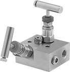
Also known as block and bleed valves, these have two vent ports to isolate pressure gauges, switches, and other components in high-pressure systems for maintenance, calibration, and sampling without interrupting the process. Turn the handle to adjust flow in small increments for metering, sampling, and other applications requiring fine flow control. All valves have metal-to-metal seats that resist temperature fluctuations. Body is 316 stainless steel for excellent corrosion resistance. Valves have a nut that can be tightened to compress the packing if it leaks.
Flow coefficient (Cv) is the amount of water (in gallons per minute) at 60° F that will flow through a fully open valve with a difference of 1 psi between the inlet and the outlet.
For technical drawings and 3-D models, click on a part number.
Threaded Precision Flow-Adjustment Valves with Gauge Ports
- Valve Type: Needle
- For Use With: See table
- Seal Material: Fluoroelastomer Rubber
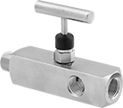
With a gauge port on each side of these valves, you can install two pieces of instrumentation equipment to simultaneously monitor multiple media properties without interrupting flow. Turn the handle to adjust flow in small increments for metering, sampling, and other applications requiring fine flow control. Valves have a 316 stainless steel body for excellent corrosion resistance.
Metal-to-metal seats resist temperature fluctuations.
Bubble-tight soft seats provide a tighter seal than metal-to-metal seats when the valve is completely closed.
Flow coefficient (Cv) is the amount of water (in gallons per minute) at 60° F that will flow through a fully open valve with a difference of 1 psi between the inlet and the outlet.
For technical drawings and 3-D models, click on a part number.
Gauge Ports | ||||||||||
|---|---|---|---|---|---|---|---|---|---|---|
| Pipe Size | No. of | Pipe Size | Gender | Thread Type | Flow Coefficient (Cv) | Max. Pressure | End-to-End Lg. | For Use With | Each | |
Steel Body—Metal-to-Metal Seat | ||||||||||
NPT Male × NPT Female | ||||||||||
| 1/2 × 1/2 | 2 | 1/2 | Female | NPT | 0.44 | 10000 psi @ 200° F | 5 3/8" | Oil, Air, Argon, Helium, Krypton, Neon, Xenon | 0000000 | 0000000 |
| 3/4 × 1/2 | 2 | 1/2 | Female | NPT | 0.44 | 10000 psi @ 200° F | 5 3/8" | Oil, Air, Argon, Helium, Krypton, Neon, Xenon | 0000000 | 000000 |
Steel Body—Bubble-Tight Soft Seat | ||||||||||
NPT Male × NPT Female | ||||||||||
| 1/2 × 1/2 | 2 | 1/2 | Female | NPT | 0.64 | 6000 psi @ 200° F | 5 3/8" | Air, Argon, Helium, Krypton, Neon, Xenon | 0000000 | 000000 |
| 3/4 × 1/2 | 2 | 1/2 | Female | NPT | 0.64 | 6000 psi @ 200° F | 5 3/8" | Air, Argon, Helium, Krypton, Neon, Xenon | 0000000 | 000000 |
316 Stainless Steel Body—Metal-to-Metal Seat | ||||||||||
NPT Male × NPT Female | ||||||||||
| 1/2 × 1/2 | 2 | 1/2 | Female | NPT | 0.44 | 10000 psi @ 200° F | 5 3/8" | Water, Oil, Air, Argon, Helium, Krypton, Neon, Xenon | 0000000 | 000000 |
| 3/4 × 1/2 | 2 | 1/2 | Female | NPT | 0.44 | 10000 psi @ 200° F | 5 3/8" | Water, Oil, Air, Argon, Helium, Krypton, Neon, Xenon | 0000000 | 000000 |
316 Stainless Steel Body—Bubble-Tight Soft Seat | ||||||||||
NPT Male × NPT Female | ||||||||||
| 1/2 × 1/2 | 2 | 1/2 | Female | NPT | 0.64 | 6000 psi @ 200° F | 5 3/8" | Water, Air, Argon, Helium, Krypton, Neon, Xenon | 0000000 | 000000 |
| 3/4 × 1/2 | 2 | 1/2 | Female | NPT | 0.64 | 6000 psi @ 200° F | 5 3/8" | Water, Air, Argon, Helium, Krypton, Neon, Xenon | 0000000 | 000000 |
Threaded Precision Flow-Adjustment Valves with Vent Port
- Valve Type: Needle
- For Use With: See table
- Seal Material: Fluoroelastomer Rubber
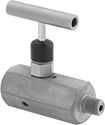
Also known as block and bleed valves, these have a vent port that allows you to remove instrumentation equipment attached to the valve without depressurizing your line. Turn the handle to shut off flow and remove the vent port plug to drain liquid trapped in the valve. Valves adjust flow in small increments for metering, sampling, and other applications requiring fine flow control.
316 stainless steel valves are more corrosion resistant than steel valves.
Bubble-tight soft seats provide a tighter seal than metal-to-metal seats when the valve is completely closed.
Flow coefficient (Cv) is the amount of water (in gallons per minute) at 60° F that will flow through a fully open valve with a difference of 1 psi between the inlet and the outlet.
For technical drawings and 3-D models, click on a part number.
| Pipe Size | Flow Coefficient (Cv) | Max. Pressure | End-to-End Lg. | For Use With | Each | |
316 Stainless Steel Body—Bubble-Tight Soft Seat | ||||||
|---|---|---|---|---|---|---|
NPT Female × NPT Male | ||||||
| 1/2 | 0.76 | 6000 psi @ 200° F | 3 1/2" | Water, Air, Argon, Helium, Krypton, Neon, Xenon | 0000000 | 0000000 |
Flow-Adjustment Valve Manifolds for Vented Systems


For use in clean environments, these manifolds have multiple air vents that keep pressure balanced. Use them to serve multiple lubrication points from a single location. Adjust the flow to individual lubrication points by turning the dial on the corresponding valve. Each valve can be removed for cleaning without disturbing the rest of the system. They can be used with any oil grade. Flow rate depends on temperature. They have NPTF (Dryseal) threads, which are compatible with NPT threads.
For technical drawings and 3-D models, click on a part number.
Oil Outlet | Oil Inlet | Overall | |||||||||||||
|---|---|---|---|---|---|---|---|---|---|---|---|---|---|---|---|
| No. of | For Tube OD | Gender | Location | Thread Type | Pipe Size | Gender | Ht. | Wd. | Dp. | Material | Temp. Range, °F | Mounting Thread Size | Features | Each | |
| 2 | 1/4" | Female | Top | NPTF | 1/4 | Female | 3 13/16" | 4 3/16" | 1 11/16" | Aluminum | -30° to 250° | 5/8"-18 | Glass Flow Sight | 0000000 | 0000000 |
| 3 | 1/4" | Female | Top | NPTF | 1/4 | Female | 3 13/16" | 4 15/16" | 1 11/16" | Aluminum | -30° to 250° | 5/8"-18 | Glass Flow Sight | 0000000 | 000000 |
| 4 | 1/4" | Female | Top | NPTF | 1/4 | Female | 3 13/16" | 5 11/16" | 1 11/16" | Aluminum | -30° to 250° | 5/8"-18 | Glass Flow Sight | 0000000 | 000000 |
Flow-Adjustment Valve Manifolds for Sealed Systems


A sealed design prevents contamination in dirty and dusty environments. Use these manifolds to serve multiple lubrication points from a single location. Adjust the flow to individual lubrication points by turning the dial on the corresponding valve. Each valve can be removed for cleaning without disturbing the rest of the system. They can be used with any oil grade. Flow rate depends on temperature. They have NPTF (Dryseal) threads, which are compatible with NPT threads.
For technical drawings and 3-D models, click on a part number.
Oil Outlet | Oil Inlet | Overall | ||||||||||||||
|---|---|---|---|---|---|---|---|---|---|---|---|---|---|---|---|---|
| No. of | For Tube OD | Gender | Location | Thread Type | Pipe Size | Gender | Ht. | Wd. | Dp. | Max. Oil Outlet Pressure, psi | Material | Temp. Range, °F | Mounting Thread Size | Features | Each | |
| 2 | 1/4" | Female | Top | NPTF | 1/4 | Female | 3 13/16" | 4 3/16" | 1 11/16" | 125 | Aluminum | -30° to 250° | 5/8"-18 | Glass Flow Sight | 0000000 | 0000000 |
| 3 | 1/4" | Female | Top | NPTF | 1/4 | Female | 3 13/16" | 4 15/16" | 1 11/16" | 125 | Aluminum | -30° to 250° | 5/8"-18 | Glass Flow Sight | 0000000 | 000000 |
| 4 | 1/4" | Female | Top | NPTF | 1/4 | Female | 3 13/16" | 5 11/16" | 1 11/16" | 125 | Aluminum | -30° to 250° | 5/8"-18 | Glass Flow Sight | 0000000 | 000000 |
Air Conditioner Charging and Testing Manifolds
Monitor refrigerant pressure with analog gauges when servicing air conditioning systems. All manifolds have double O-ring piston valves. Manifolds with sight glass allow you to view liquid levels.
Replacement gauges are sold separately.
Optional gauge cover sets (sold separately) include one blue and one red gauge cover. They are not for use with the manifolds for R-410A refrigerant.
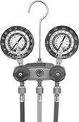
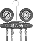
Hose | ||||||||
|---|---|---|---|---|---|---|---|---|
| For Refrigerant Number | Valve Material | Connection | Lg., ft. | Dia. | Color | Includes | Each | |
Two Valve | ||||||||
| R-134A | Brass | 1/2"-16 Acme × 7/16"-20 UNF × 7/16"-20 UNF | 6 | 2 1/2" | One Blue and One Red | __ | 0000000 | 0000000 |
| R-134A, R-404A, R-407C | Aluminum | 1/4 UN/UNF (SAE 45°) × 1/4 UN/UNF (SAE 45°) × 1/4 UN/UNF (SAE 45°) | 5 | 3 1/8" | One Blue and One Red | Sight Glass | 0000000 | 000000 |
| R-22, R-404A, R-410A | Aluminum | 1/4 UN/UNF (SAE 45°) × 1/4 UN/UNF (SAE 45°) × 1/4 UN/UNF (SAE 45°) | 5 | 3 1/8" | One Blue and One Red | Sight Glass | 0000000 | 000000 |
| R-410A | Brass | 1/4 UN/UNF (SAE 45°) × 1/4 UN/UNF (SAE 45°) × 1/4 UN/UNF (SAE 45°) | 5 | 2 1/2" | One Blue and One Red | __ | 0000000 | 000000 |
Four Valve | ||||||||
| R-134A, R-404A, R-407C | Aluminum | 1/4 UN/UNF (SAE 45°) × 1/4 UN/UNF (SAE 45°) × 1/4 UN/UNF (SAE 45°) × 3/8 UN/UNF (SAE 45°) | 5 | 3 1/8" | One Blue and One Red | Sight Glass | 0000000 | 000000 |
| R-22, R-404A, R-410A | Aluminum | 1/4 UN/UNF (SAE 45°) × 1/4 UN/UNF (SAE 45°) × 1/4 UN/UNF (SAE 45°) × 3/8 UN/UNF (SAE 45°) | 5 | 3 1/8" | One Blue and One Red | Sight Glass | 0000000 | 000000 |

| For Manifold Type | Includes | Each | |
| Two Valve, Four Valve | One Blue Cover, One Red Cover | 0000000 | 000000 |
Digital Air Conditioner Charging and Testing Manifolds
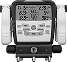
Monitor refrigerant pressure on an LCD when servicing air conditioning systems. This manifold automatically calculates how much refrigerant is needed in a system based on measurements taken with its thermocouples.
Display | |||||||
|---|---|---|---|---|---|---|---|
| For Refrigerant Number | Valve Material | Pipe Connection | Type | Size | Batteries Included | Each | |
Three Valve | |||||||
| R-12, R-134A, R-22, R-404A, R-407C, R-410A, R-502 | Brass | 1/4 NPT × 1/4 NPT × 1/4 NPT | Digital | 5" | Yes | 0000000 | 0000000 |


