About Pipe Size
More
About Pressure Gauges
More
About Pressure Transmitters
More
About Gas Regulators
More
Gas Pressure Gauges
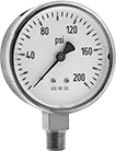
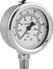
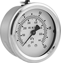
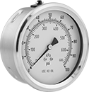


Use these gauges with pumps, filters, regulators, and in process lines to monitor the pressure of compressed gas. Mount them with the dial face upright. Gauges for use with acetylene can also be used in welding applications.
Gauges with brass case are cleaned to meet ASME B40.1, Level IV for oxygen service.
Gauges with 304 stainless steel case are cleaned and bagged to meet ASME B40.1, Level IV for oxygen service.
For technical drawings and 3-D models, click on a part number.
- For Use With: Air, Acetylene, Carbon Dioxide, and Oxygen
- Accuracy: ±2% Mid Scale (Grade B)
Available Pressure Ranges | ||
|---|---|---|
| Pressure Range, psi | Graduation Marks, psi | Numeric Increments, psi |
| 0 to 30 | 1 | 5 |
| 0 to 60 | 1 | 10 |
| 0 to 100 | 2 | 20 |
| 0 to 200 | 5 | 40 |
| 0 to 400 | 10 | 50 |
| 0 to 600 | 10 | 100 |
| 0 to 1,000 | 20 | 200 |
| 0 to 2,000 | 50 | 400 |
| 0 to 3,000 | 50 | 500 |
| 0 to 4,000 | 100 | 500 |
- For Use With: Oxygen
- Accuracy: ±1% Mid Scale (Grade A); except
4" Dial Dia.: ±1% Full Scale (Grade 1A)
Available Pressure Ranges | |||||||||
|---|---|---|---|---|---|---|---|---|---|
Bottom and Center Back Connections | Lower Back Connection | ||||||||
Pressure Range | Graduation Marks | Numeric Increments | Graduation Marks | Numeric Increments | |||||
| psi | kPa | psi | kPa | psi | kPa | psi | kPa | psi | kPa |
2 1/2" Dial Diameter | |||||||||
| 0 to 15 | 0 to 102 | 0.2 | 2 | 3 | 20 | __ | __ | __ | __ |
| 0 to 30 | 0 to 205 | 0.5 | 5 | 5 | 50 | __ | __ | __ | __ |
| 0 to 100 | 0 to 680 | 2 | 10 | 20 | 100 | __ | __ | __ | __ |
| 0 to 200 | 0 to 1,350 | 5 | 50 | 50 | 200 | __ | __ | __ | __ |
| 0 to 300 | 0 to 2,050 | 5 | 50 | 50 | 500 | __ | __ | __ | __ |
| 0 to 600 | 0 to 4,100 | 10 | 100 | 100 | 1,000 | __ | __ | __ | __ |
4" Dial Diameter | |||||||||
| 0 to 15 | 0 to 103 | 0.2 | 1 | 3 | 10 | 0.2 | 1 | 3 | 10 |
| 0 to 30 | 0 to 206 | 0.5 | 2 | 5 | 20 | 0.5 | 2 | 5 | 20 |
| 0 to 100 | 0 to 680 | 1 | 10 | 10 | 100 | 1 | 10 | 10 | 100 |
| 0 to 200 | 0 to 1,360 | 2 | 20 | 20 | 200 | 2 | 20 | 20 | 200 |
| 0 to 300 | 0 to 2,060 | 5 | 20 | 50 | 200 | 5 | 20 | 50 | 200 |
| 0 to 600 | 0 to 4,100 | 10 | 50 | 100 | 500 | 10 | 100 | 100 | 1,000 |
| Dial Diameter | Pipe Size | Environment Temp. Range, °F | Process Temp. Range, °F | Mounting Orientation | Each | |
Bottom Connection | ||||||
|---|---|---|---|---|---|---|
NPT Male | ||||||
| 2 1/2" | 1/4 | -40° to 140° | -40° to 140° | Upright | 0000000 | 000000 |
| 4" | 1/4 | -40° to 140° | -40° to 140° | Upright | 0000000 | 00000 |
Center Back Connection | ||||||
NPT Male | ||||||
| 2 1/2" | 1/4 | -40° to 140° | -40° to 140° | Upright | 0000000 | 00000 |
Lower Back Connection | ||||||
NPT Male | ||||||
| 4" | 1/4 | -40° to 140° | -40° to 140° | Upright | 0000000 | 00000 |
Gauge Guards

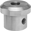
Also known as isolators or diaphragm seals, these protect gauges from corrosive process media. Fill guards with hydraulic oil (not included) before use.
316 stainless steel guards provide excellent corrosion and chemical resistance and can handle higher temperatures and pressures than plastic guards.
Guards with drain port allow you to remove process media.
For technical drawings and 3-D models, click on a part number.
Pipe Connections | |||||||||
|---|---|---|---|---|---|---|---|---|---|
| Inlet | Outlet | Gasket Material | For Use With | Min. Pressure, psi | Max. Pressure | Max. Temp., °F | Ht. | Each | |
316 Stainless Steel Body | |||||||||
| 1/4 NPT Female | 1/4 NPT Female | 316 Stainless Steel | Acetylene, Air, Ammonia, Argon, Bleach, Boric Acid, Carbon Dioxide, Deionized Water, Diesel Fuel, Ethanol, Ethyl Alcohol, Gasoline, Hydraulic Fluid, Hydraulic Oil, Hydrogen, Liquid Nitrogen, Mineral Oil, Natural Gas, Nitrogen, Oxygen, Refrigerant, Salt Water, Steam, Water | 60 | 2,500 psi @ 72° F | 300° | 1 3/4" | 0000000 | 0000000 |
| 1/2 NPT Female | 1/4 NPT Female | 316 Stainless Steel | Acetylene, Air, Ammonia, Argon, Bleach, Boric Acid, Carbon Dioxide, Deionized Water, Diesel Fuel, Ethanol, Ethyl Alcohol, Gasoline, Hydraulic Fluid, Hydraulic Oil, Hydrogen, Liquid Nitrogen, Mineral Oil, Natural Gas, Nitrogen, Oxygen, Refrigerant, Salt Water, Steam, Water | 60 | 2,500 psi @ 72° F | 300° | 1 3/4" | 0000000 | 000000 |
| 1/2 NPT Female | 1/2 NPT Female | 316 Stainless Steel | Acetylene, Air, Ammonia, Argon, Bleach, Boric Acid, Carbon Dioxide, Deionized Water, Diesel Fuel, Ethanol, Ethyl Alcohol, Gasoline, Hydraulic Fluid, Hydraulic Oil, Hydrogen, Liquid Nitrogen, Mineral Oil, Natural Gas, Nitrogen, Oxygen, Refrigerant, Salt Water, Steam, Water | 60 | 2,500 psi @ 72° F | 300° | 1 1/2" | 0000000 | 000000 |
316 Stainless Steel Body with 1/4 NPT Female Drain Port | |||||||||
| 1/4 NPT Female | 1/4 NPT Female | 316 Stainless Steel | Acetylene, Air, Ammonia, Argon, Bleach, Boric Acid, Carbon Dioxide, Deionized Water, Diesel Fuel, Ethanol, Ethyl Alcohol, Gasoline, Hydraulic Fluid, Hydraulic Oil, Hydrogen, Liquid Nitrogen, Mineral Oil, Natural Gas, Nitrogen, Oxygen, Refrigerant, Salt Water, Steam, Water | 60 | 2,500 psi @ 72° F | 300° | 2" | 0000000 | 000000 |
| 1/2 NPT Female | 1/4 NPT Female | 316 Stainless Steel | Acetylene, Air, Ammonia, Argon, Bleach, Boric Acid, Carbon Dioxide, Deionized Water, Diesel Fuel, Ethanol, Ethyl Alcohol, Gasoline, Hydraulic Fluid, Hydraulic Oil, Hydrogen, Liquid Nitrogen, Mineral Oil, Natural Gas, Nitrogen, Oxygen, Refrigerant, Salt Water, Steam, Water | 60 | 2,500 psi @ 72° F | 300° | 2" | 0000000 | 000000 |
| 1/2 NPT Female | 1/2 NPT Female | 316 Stainless Steel | Acetylene, Air, Ammonia, Argon, Bleach, Boric Acid, Carbon Dioxide, Deionized Water, Diesel Fuel, Ethanol, Ethyl Alcohol, Gasoline, Hydraulic Fluid, Hydraulic Oil, Hydrogen, Liquid Nitrogen, Mineral Oil, Natural Gas, Nitrogen, Oxygen, Refrigerant, Salt Water, Steam, Water | 60 | 2,500 psi @ 72° F | 300° | 2" | 0000000 | 000000 |
Sanitary Gauge Guards
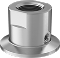
Keeping corrosive substances from touching pressure gauges used in food-processing and pharmaceutical plants, these guards have a sanitary design. Made of 316 stainless steel, they won’t rust from frequent washdowns with harsh cleaners and sanitizers. They have continuously-welded seams and polished surfaces, so there aren’t any pits for bacteria to grow in. Removing them for cleaning and maintenance is easy thanks to their quick-clamp connection, which is sometimes called a tri-clamp.
Also known as isolators and diaphragm seals, these guards have a 316 stainless steel gasket to shield the pressure gauges from corrosion. Before use, fill the guards with fluid such as glycerin or silicone that’s suitable for food contact.
For technical drawings and 3-D models, click on a part number.
Outlet Quick-Clamp Tube Connection | |||||||||||
|---|---|---|---|---|---|---|---|---|---|---|---|
| Inlet Pipe Connection | For Tube OD | Flange OD | Gasket Material | For Use With | Minimum Pressure, psi | Maximum Pressure | Maximum Temperature | Height | Interior Smoothness, Ra | Each | |
316 Stainless Steel Body | |||||||||||
| 1/4 NPT Female | 1 1/2" | 1.984" | 316 Stainless Steel | Acetylene, Air, Ammonia, Beverage, Boric Acid, Carbon Dioxide, Diesel Fuel, Ethanol, Food, Gasoline, Hydraulic Fluid, Hydrogen, Oxygen, Pharmaceuticals, Wastewater, Water | 30 | Not Rated | Not Rated | 1 3/8" | 32 | 0000000 | 0000000 |
| 1/4 NPT Female | 2" | 2.516" | 316 Stainless Steel | Acetylene, Air, Ammonia, Beverage, Boric Acid, Carbon Dioxide, Diesel Fuel, Ethanol, Food, Gasoline, Hydraulic Fluid, Hydrogen, Oxygen, Pharmaceuticals, Wastewater, Water | 30 | Not Rated | Not Rated | 1 1/8" | 32 | 0000000 | 000000 |
| 1/2 NPT Female | 1 1/2" | 1.984" | 316 Stainless Steel | Acetylene, Air, Ammonia, Beverage, Boric Acid, Carbon Dioxide, Diesel Fuel, Ethanol, Food, Gasoline, Hydraulic Fluid, Hydrogen, Oxygen, Pharmaceuticals, Wastewater, Water | 30 | Not Rated | Not Rated | 1 3/8" | 32 | 0000000 | 000000 |
Pressure Transmitters for Oxygen

- For Use With: Oxygen
- Accuracy: ±1.0%
- Pipe Connection: NPT Male
- Housing Material: Glass-Reinforced Nylon
- Connection Material: 304 Stainless Steel
- Temperature Range: -40° to 255° F
Adhere to safety standards and monitor pressure when working with high concentrations of oxygen. These transmitters are cleaned following ASME B40.100 IV guidelines and are sealed in an airtight bag to prevent contamination before use. Also known as transducers, they convert pressure to an electrical signal that can be interpreted by receiving devices, such as remote displays, programmable logic controllers, and motor speed controls. For your receiving device to interpret the signal from the transmitter, you will need to calibrate it for the transmitter's pressure range and output signal. As pressure increases, the output signal from the transmitter will increase. Transmitters will only provide accurate readings within the rated pressure range.
These transmitters are rated NEMA 4X and IP65 for protection from dust, weather, washdown, and corrosion. UL and C-UL recognized components and CE marked, they also meet American, Canadian, and European safety standards.
With a current output, they connect using two wires. The same wire is used to send a signal to the receiver and to power the transmitter. Current doesn’t lose signal over long distances and isn’t affected by electrical interference from other devices.
For technical drawings and 3-D models, click on a part number.
| Pressure Range, psi | Maximum Continuous Pressure, psi | Maximum Short-Term Pressure, psi | Input Voltage | Pipe Size | Ht. | Wd. | Environmental Rating | Each | |
4-20mA Current Output—Wire Leads | |||||||||
|---|---|---|---|---|---|---|---|---|---|
| 0-30 | 60 | 60 | 9-36V DC | 1/4 | 2 3/8" | 1 5/16" | IP65, NEMA 4X | 0000000 | 0000000 |
| 0-60 | 120 | 120 | 9-36V DC | 1/4 | 2 3/8" | 1 5/16" | IP65, NEMA 4X | 0000000 | 000000 |
| 0-100 | 200 | 200 | 9-36V DC | 1/4 | 2 3/8" | 1 5/16" | IP65, NEMA 4X | 0000000 | 000000 |
| 0-300 | 600 | 600 | 9-36V DC | 1/4 | 2 3/8" | 1 5/16" | IP65, NEMA 4X | 0000000 | 000000 |
| 0-500 | 1,000 | 1,000 | 9-36V DC | 1/4 | 2 3/8" | 1 5/16" | IP65, NEMA 4X | 0000000 | 000000 |
| 0-1,000 | 2,000 | 2,000 | 9-36V DC | 1/4 | 2 3/8" | 1 5/16" | IP65, NEMA 4X | 0000000 | 000000 |
| 0-1,500 | 3,000 | 3,000 | 9-36V DC | 1/4 | 2 3/8" | 1 5/16" | IP65, NEMA 4X | 0000000 | 000000 |
Clean Room Pressure-Regulating Valves for Water, Air, and Inert Gas

- For Use With: Deionized Water, Air, Nitrogen, Oxygen
- Temperature Range: 41° to 140° F
To maintain contaminant-free standards in clean room environments, these valves come cleaned and bagged to Fed. Std. Class 100 and ISO Class 5 clean room standards and have a 316 stainless steel body with a smooth finish to resist dust collection. They automatically reduce a high, variable inlet pressure to a lower, stable output pressure. Adjust the outlet pressure within the range. Valves are no-bleed style, so they keep process media contained within the valve.
For technical drawings and 3-D models, click on a part number.
Inlet | Outlet | ||||||||
|---|---|---|---|---|---|---|---|---|---|
| Thread Size | Location | Max. Pressure, psi | Thread Size | Location | Pressure Range, psi | End-to-End Lg. | Environmental Rating | Each | |
Metric Female | |||||||||
316 Stainless Steel Body—Fluoroelastomer Diaphragm and 316 Stainless Steel Seal | |||||||||
| M5 × 0.8 mm | Side | 150 | M5 × 0.8 mm | Side | 1.4 to 28 | 1 3/16" | Fed. Std. Class 100, ISO Class 5 | 00000000 | 0000000 |
| M5 × 0.8 mm | Side | 150 | M5 × 0.8 mm | Side | 7 to 99 | 1 3/16" | Fed. Std. Class 100, ISO Class 5 | 00000000 | 000000 |
Cleaned and Bagged Pressure-Regulating Valves for Air and Inert Gas

- For Use With: Nitrogen, Oxygen, Argon, Helium, Neon
- Temperature Range: -40° to 165° F
Often used for oxygen service and other high-purity applications, these valves are cleaned and bagged to meet CGA G-4.1 standards to prevent contamination. They automatically reduce a high, variable inlet pressure to a lower, stable outlet pressure. Adjust the outlet pressure within the range. Valves have two gauge ports. They are no-bleed style, so they keep process gases contained in the valve.
For technical drawings and 3-D models, click on a part number.
Inlet | Outlet | Gauge Port | ||||||||
|---|---|---|---|---|---|---|---|---|---|---|
| Pipe Size | Location | Max. Pressure, psi | Pipe Size | Location | Pipe Size | Location | End-to-End Lg. | Choose an Outlet Pressure Range, psi | Each | |
NPT Female | ||||||||||
Brass Body—Buna-N Diaphragm and Fluoroelastomer Seal | ||||||||||
| 1/2 | Side | 500 | 1/2 | Side | 1/4 | Side | 2 13/16" | 00000000 | 0000000 | |
| 3/4 | Side | 500 | 3/4 | Side | 1/4 | Side | 3 5/16" | 00000000 | 000000 | |
| 1 | Side | 500 | 1 | Side | 1/4 | Side | 3 5/16" | 00000000 | 000000 | |
Tank-Mount Pressure-Regulating Valves for Air and Inert Gas
- For Use With: See Table
- Temperature Range: -20° to 120° F
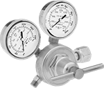
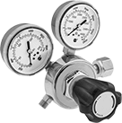
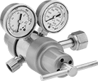
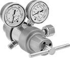
These valves automatically reduce a high inlet pressure from compressed gas tanks to a lower, stable outlet pressure. All have Compressed Gas Association (CGA) numbered inlet fittings for secure connections to compressed gas tanks. Choose a valve with the same CGA number as your tank and other system components. Valves have a gauge to monitor outlet pressure and a gauge to monitor inlet pressure from the tank.
Choose a valve with a maximum outlet pressure that’s approximately twice your application’s normal operating pressure. Your operating pressure should never exceed 75% of the valve’s maximum outlet pressure.
Single-stage valves reduce pressure in one step, which causes the outlet pressure to fluctuate slightly as you empty the tank. They’re best for applications where a constant outlet pressure isn’t critical.
Two-stage valves progressively reduce pressure over two steps for more consistent outlet pressure at all times. They’re often used in applications that require a constant outlet pressure regardless of the tank level.
Valves with a brass body have a longer service life than valves with a brass and steel body.
Valves with a stainless steel diaphragm can withstand harsh environments.
Inlet | Outlet | Material | ||||||||||
|---|---|---|---|---|---|---|---|---|---|---|---|---|
| CGA Number | Location | Thread Direction | Pressure Gauge Range, psi | Location | Thread Direction | Pressure Range, psi | Pressure Adjustment Method | Body | Seal | Diaphragm | Each | |
For Use With Oxygen | ||||||||||||
9/16"-18 UNF Male Outlet × NGO Female Inlet | ||||||||||||
| CGA 540 | Side | Right Hand | 0 to 4,000 | Side | Left Hand | 0 to 50 | Knob | Brass | PTFE | Neoprene | 00000000 | 0000000 |
| CGA 540 | Side | Right Hand | 0 to 4,000 | Side | Right Hand | 0 to 50 | T-Handle | Brass | PTFE | Neoprene | 00000000 | 000000 |
| CGA 540 | Side | Right Hand | 0 to 4,000 | Side | Right Hand | 0 to 50 | T-Handle | Brass | PTFE | Stainless Steel | 00000000 | 000000 |
| CGA 540 | Side | Right Hand | 0 to 4,000 | Side | Right Hand | 0 to 125 | T-Handle | Brass | PTFE | Rubber | 0000000 | 000000 |
| CGA 540 | Side | Right Hand | 0 to 4,000 | Side | Right Hand | 0 to 125 | T-Handle | Brass | PTFE | Stainless Steel | 0000000 | 000000 |
| CGA 540 | Side | Right Hand | 0 to 4,000 | Side | Right Hand | 0 to 145 | Knob | Brass/Steel | PTFE | Rubber | 0000000 | 000000 |
| CGA 540 | Side | Right Hand | 0 to 4,000 | Side | Right Hand | 0 to 200 | T-Handle | Brass | PTFE | Rubber | 000000 | 000000 |
| CGA 540 | Side | Right Hand | 0 to 4,000 | Side | Right Hand | 0 to 200 | T-Handle | Brass | PTFE | Stainless Steel | 00000000 | 000000 |
Inlet | Outlet | Material | ||||||||||
|---|---|---|---|---|---|---|---|---|---|---|---|---|
| CGA Number | Location | Thread Direction | Pressure Gauge Range, psi | Location | Thread Direction | Pressure Range, psi | Pressure Adjustment Method | Body | Seal | Diaphragm | Each | |
For Use With Oxygen | ||||||||||||
1/4 NPT Female Outlet × NGO Female Inlet | ||||||||||||
| CGA 540 | Side | Right Hand | 0 to 4,000 | Side | Right Hand | 0 to 250 | T-Handle | Brass | PTFE | Neoprene | 0000000 | 0000000 |
| CGA 540 | Side | Right Hand | 0 to 4,000 | Side | Right Hand | 0 to 250 | T-Handle | Brass | PTFE | Stainless Steel | 0000000 | 000000 |
9/16"-18 UNF Male Outlet × NGO Female Inlet | ||||||||||||
| CGA 540 | Side | Right Hand | 0 to 4,000 | Side | Right Hand | 0 to 50 | T-Handle | Brass | PTFE | Neoprene | 00000000 | 000000 |
| CGA 540 | Side | Right Hand | 0 to 4,000 | Side | Right Hand | 0 to 50 | T-Handle | Brass | PTFE | Stainless Steel | 00000000 | 000000 |
| CGA 540 | Side | Right Hand | 0 to 4,000 | Side | Right Hand | 0 to 125 | T-Handle | Brass | PTFE | Stainless Steel | 0000000 | 000000 |
| CGA 540 | Side | Right Hand | 0 to 4,000 | Side | Right Hand | 0 to 125 | T-Handle | Brass/Steel | PTFE | Rubber | 000000 | 000000 |
Tank-Mount High-Pressure-Regulating Valves for Air and Inert Gas
- For Use With: See Table
- Temperature Range: -20° to 120° F
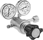
Often used for pressure-vessel testing and other high-pressure applications, these valves can handle at least seven times the outlet pressure of standard tank-mount pressure-regulating valves. They automatically reduce a high inlet pressure from compressed gas tanks to a lower, stable outlet pressure. All have Compressed Gas Association (CGA) numbered inlet fittings for secure connections to compressed gas tanks. Choose a valve with the same CGA number as your tank and other system components. Outlet fittings are Swagelok® for a leak-free seal around hard metal tubing in high-pressure lines. Also known as instrumentation fittings, Swagelok® fittings are compatible with Parker A-Lok, Gyrolok, Bilok, and Tylok fittings. Valves have a gauge to monitor outlet pressure and a gauge to monitor inlet pressure from the tank. They are single stage and reduce pressure in one step, which causes the outlet pressure to fluctuate slightly as you empty the tank.
Choose a valve with a maximum outlet pressure that’s approximately twice your application’s normal operating pressure. Your operating pressure should never exceed 75% of the valve’s maximum outlet pressure.
Inlet | Outlet | Material | ||||||||||||
|---|---|---|---|---|---|---|---|---|---|---|---|---|---|---|
| CGA Number | Location | Thread Direction | Pressure Gauge Range, psi | Stage | For Tube OD | Location | Pressure Range, psi | Pressure Adjustment Method | Shape | Body | Seal | Diaphragm | Each | |
NGO Female Inlet × Swagelok® Female Outlet | ||||||||||||||
| CGA 540 | Side | Right Hand | 0 to 4,000 | Single | 1/4" | Side | 0 to 1,500 | Knob | Straight | Brass | PCTFE | Neoprene | 0000000 | 0000000 |
| CGA 540 | Side | Right Hand | 0 to 4,000 | Single | 1/4" | Side | 0 to 2,500 | Knob | Straight | Brass | PCTFE | Neoprene | 0000000 | 000000 |
Tank-Mount Pressure-Regulating Valves for Cryogenic Cylinders
- For Use With: See Table
- Temperature Range: -20° to 120° F
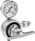
Automatically reduce a high inlet pressure from compressed gas tanks to a lower, stable outlet pressure. These valves can remove gases from liquid cryogenic cylinders. They have Compressed Gas Association (CGA) numbered inlet fittings for secure connections to compressed gas tanks. Choose a valve with the same CGA number as your tank and other system components. Valves come with a gauge to monitor outlet pressure. They are single stage and reduce pressure in one step, which causes the outlet pressure to fluctuate slightly as you empty the tank.
Choose a valve with a maximum outlet pressure that’s approximately twice your application’s normal operating pressure. Your operating pressure should never exceed 75% of the valve’s maximum outlet pressure.
Inlet | Outlet | ||||||||||
|---|---|---|---|---|---|---|---|---|---|---|---|
| For Use With | CGA Number | Location | Thread Direction | Stage | Thread Size | Location | Thread Direction | Pressure Range, psi | Pressure Adjustment Method | Each | |
UNF Male Outlet × NGO Female Inlet | |||||||||||
Brass Body—Stainless Steel Diaphragm and PTFE Seal | |||||||||||
| Oxygen | CGA 540 | Side | Right Hand | Single | 9/16"-18 | Bottom | Right Hand | 0 to 125 | T-Handle | 0000000 | 0000000 |


