


Input/Output Modules for Programmable Logic Controllers
Connect switches, transmitters, actuators, and other equipment to your programmable logic controller (PLC) for complex automation jobs. To operate, attach these modules to a PLC power supply and a processor (not included). Once the processor has been programmed and your system has been configured, the input modules receive an electrical signal from your switches or sensors and transfer it to the processor. The processor then communicates with the output modules, which send a signal to your receiving devices, such as circulation pumps or motor starters. Connect up to 10 different modules per power supply and processor. Mount them to a 35-mm DIN rail.
Rated IP20, these modules prevent your fingers from touching internal components and accidentally shocking yourself. With various domestic and international certifications, they meet strict standards for quality and safety. Some meet additional military standards for electrical connections.
Digital Modules
These modules send and receive on-off or high-low electrical signals to and from your equipment. Configure digital input modules to receive these signals from devices such as push-buttons and proximity switches. Choose digital output modules to activate instruments that switch on and off, such as indicator lights, buzzers, and solenoid valves. Digital input/output modules combine both functions into one unit, saving space and wiring on your PLC setup.
Modules with PNP/NPN inputs can automatically read both signal types without needing to select the polarity.
Modules with transistor signal outputs are used for handling DC loads. They’re faster and have a longer lifespan than relay outputs. Triac signals are similar to transistors but handle AC loads. Relay signals are slower than triacs and transistors, but they can handle higher loads for either AC or DC. Because of their moving parts, they wear out quicker than transistors and triacs.
Analog Modules
Use these modules to send and receive electrical signals within a defined range of values. A dial on the modules lets you set your preferred range. Pair analog input modules with temperature sensors, pressure transmitters, and other devices that can generate these signals. Analog output modules convert these signals to make precise adjustments on your equipment. They’re commonly used with motor speed controls and flow-adjustment valves. Analog input/output modules are capable of both functions to save space for a simpler automated system. Choose analog temperature-control-loop modules to control temperatures without slowing down your processor with extra tasks. They’re equipped with both inputs and outputs.
![]() For technical drawings and 3-D models, click on a part number.
For technical drawings and 3-D models, click on a part number.


Inputs | ||||||||||||||
|---|---|---|---|---|---|---|---|---|---|---|---|---|---|---|
| Voltage | Current | No. of | Signal Type | Transistor Type | Features | Wire Connection Type | Terminal Size | Plug Type | No. of Poles | Ht. | Wd. | Dp. | Each | |
For Omron CJ1, CJ2 Series | ||||||||||||||
| 100 to 120V AC | 7mA | 16 | __ | __ | __ | Screw Terminals | M3 | __ | __ | 3.5" | 1.2" | 3.5" | 0000000 | 0000000 |
| 200 to 240V AC | 10mA | 8 | __ | __ | __ | Screw Terminals | M3 | __ | __ | 3.5" | 1.2" | 3.5" | 0000000 | 000000 |
| 24V DC | 10mA | 8 | Transistor | PNP/NPN | __ | Screw Terminals | M3 | __ | __ | 3.5" | 1.2" | 3.5" | 0000000 | 000000 |
| 24V DC | 7mA | 16 | Transistor | PNP/NPN | __ | Spring-Clamp Terminals | __ | __ | __ | 3.5" | 1.2" | 3.5" | 0000000 | 000000 |
| 24V DC | 7mA | 16 | Transistor | PNP/NPN | __ | Screw Terminals | M3 | __ | __ | 3.5" | 1.2" | 3.5" | 0000000 | 000000 |
| 24V DC | 7mA | 16 | Transistor | PNP/NPN | Fast Response | Screw Terminals | M3 | __ | __ | 3.5" | 1.2" | 3.5" | 0000000 | 000000 |
| 24V DC | 7mA | 16 | Transistor | PNP/NPN | Pulse Latch | Screw Terminals | M3 | __ | __ | 3.5" | 1.2" | 3.5" | 0000000 | 000000 |
| 24V DC | 7mA | 16 | Transistor | PNP/NPN | Interrupt Tasks | Screw Terminals | M3 | __ | __ | 3.5" | 1.2" | 3.5" | 0000000 | 000000 |
| 24V DC | 4.1mA | 32 | Transistor | PNP/NPN | __ | Plug In | __ | FCN | 40 | 3.5" | 0.8" | 2.6" | 0000000 | 000000 |
| 24V DC | 4.1mA | 32 | Transistor | PNP/NPN | __ | Plug In | __ | MIL | 40 | 3.5" | 0.8" | 3.3" | 0000000 | 000000 |
| 24V DC | 4.1mA | 32 | Transistor | PNP/NPN | Fast Response | Plug In | __ | MIL | 40 | 3.5" | 0.8" | 3.3" | 0000000 | 000000 |
| 24V DC | 4.1mA | 64 | Transistor | PNP/NPN | __ | Plug In | __ | FCN | 40 | 3.5" | 0.8" | 2.6" | 0000000 | 00000000 |
| 24V DC | 4.1mA | 64 | Transistor | PNP/NPN | __ | Plug In | __ | MIL | 40 | 3.5" | 1.2" | 3.3" | 0000000 | 00000000 |


Outputs | |||||||||||||||
|---|---|---|---|---|---|---|---|---|---|---|---|---|---|---|---|
| Voltage | Current | No. of | Signal Type | Transistor Type | Features | Circuit Protection | Wire Connection Type | Terminal Size | Plug Type | No. of Poles | Ht. | Wd. | Dp. | Each | |
For Omron CJ1, CJ2 Series | |||||||||||||||
| 250V AC | 0.6A | 8 | Triac | __ | __ | __ | Screw Terminals | M3 | __ | __ | 3.5" | 1.2" | 3.5" | 0000000 | 0000000 |
| 250V AC 24V DC | 2A | 8 | Relay | __ | __ | __ | Screw Terminals | M3 | __ | __ | 3.5" | 1.2" | 3.5" | 0000000 | 000000 |
| 250V AC 24V DC | 2A | 16 | Relay | __ | __ | __ | Screw Terminals | M3 | __ | __ | 3.5" | 1.2" | 3.5" | 0000000 | 000000 |
| 12 to 24V DC | 0.5A | 8 | Transistor | NPN | __ | __ | Screw Terminals | M3 | __ | __ | 3.5" | 1.2" | 3.5" | 0000000 | 000000 |
| 12 to 24V DC | 2A | 8 | Transistor | NPN | __ | __ | Screw Terminals | M3 | __ | __ | 3.5" | 1.2" | 3.5" | 0000000 | 000000 |
| 12 to 24V DC | 0.5A | 32 | Transistor | NPN | __ | __ | Plug In | __ | FCN | 40 | 3.5" | 0.8" | 2.6" | 0000000 | 000000 |
| 12 to 24V DC | 0.5A | 32 | Transistor | NPN | __ | __ | Plug In | __ | MIL | 40 | 3.5" | 0.8" | 3.3" | 0000000 | 000000 |
| 12 to 24V DC | 0.3A | 64 | Transistor | NPN | __ | __ | Plug In | __ | FCN | 40 | 3.5" | 1.2" | 2.6" | 0000000 | 00000000 |
| 12 to 24V DC | 0.3A | 64 | Transistor | NPN | __ | __ | Plug In | __ | MIL | 40 | 3.5" | 1.2" | 2.6" | 0000000 | 00000000 |
| 24V DC | 0.5A | 8 | Transistor | PNP | Alarm | Short Circuit | Screw Terminals | M3 | __ | __ | 3.5" | 1.2" | 3.5" | 0000000 | 000000 |
| 24V DC | 2A | 8 | Transistor | PNP | Alarm | Short Circuit | Screw Terminals | M3 | __ | __ | 3.5" | 1.2" | 3.5" | 0000000 | 000000 |
| 24V DC | 0.5A | 16 | Transistor | NPN | __ | __ | Screw Terminals | M3 | __ | __ | 3.5" | 1.2" | 3.5" | 0000000 | 000000 |
| 24V DC | 0.5A | 16 | Transistor | PNP | Alarm | Short Circuit | Screw Terminals | M3 | __ | __ | 3.5" | 1.2" | 3.5" | 0000000 | 000000 |
| 24V DC | 0.5A | 16 | Transistor | NPN | Fast Response | __ | Screw Terminals | M3 | __ | __ | 3.5" | 1.2" | 3.5" | 0000000 | 000000 |
| 24V DC | 0.5A | 32 | Transistor | PNP | Alarm | Short Circuit | Plug In | __ | MIL | 40 | 3.5" | 0.8" | 3.3" | 0000000 | 000000 |
| 24V DC | 0.5A | 32 | Transistor | NPN | Fast Response | __ | Plug In | __ | MIL | 40 | 3.5" | 0.8" | 3.3" | 0000000 | 000000 |
| 24V DC | 0.3A | 64 | Transistor | PNP | __ | __ | Plug In | __ | MIL | 40 | 3.5" | 1.2" | 3.3" | 0000000 | 000000 |


Inputs | Outputs | ||||||||||||||||
|---|---|---|---|---|---|---|---|---|---|---|---|---|---|---|---|---|---|
| Voltage | Current | No. of | Signal Type | Transistor Type | Voltage | Current | No. of | Signal Type | Transistor Type | Wire Connection Type | Plug Type | No. of Poles | Ht. | Wd. | Dp. | Each | |
For Omron CJ1, CJ2 Series | |||||||||||||||||
| 24V DC | 0.5A | 16 | Transistor | PNP/NPN | 12 to 24V DC | 0.5A | 16 | Transistor | NPN | Plug In | FCN | 24 | 3.5" | 1.2" | 2.6" | 0000000 | 0000000 |
| 24V DC | 0.5A | 16 | Transistor | PNP/NPN | 12 to 24V DC | 0.5A | 16 | Transistor | NPN | Plug In | MIL | 20 | 3.5" | 1.2" | 3.3" | 0000000 | 000000 |
| 24V DC | 0.5A | 16 | Transistor | PNP/NPN | 24V DC | 0.5A | 16 | Transistor | PNP | Plug In | MIL | 20 | 3.5" | 1.2" | 3.3" | 0000000 | 000000 |
| 24V DC | 0.3A | 32 | Transistor | PNP/NPN | 12 to 24V DC | 0.3A | 32 | Transistor | NPN | Plug In | FCN | 40 | 3.5" | 1.2" | 2.6" | 0000000 | 00000000 |
| 24V DC | 0.3A | 32 | Transistor | PNP/NPN | 12 to 24V DC | 0.3A | 32 | Transistor | NPN | Plug In | MIL | 40 | 3.5" | 1.2" | 3.3" | 0000000 | 00000000 |
| 5V DC | 0.035A | 32 | Transistor | TTL | 5V DC | 0.035A | 32 | Transistor | TTL | Plug In | MIL | 40 | 3.5" | 1.2" | 3.3" | 0000000 | 00000000 |


Inputs | |||||||||||||
|---|---|---|---|---|---|---|---|---|---|---|---|---|---|
| Voltage | Current | No. of | Thermocouple Type | RTD Type | Conversion Time Per Input | Features | Wire Connection Type | Terminal Size | Ht. | Wd. | Dp. | Each | |
For Omron CJ1, CJ2 Series | |||||||||||||
| -10 to 10V DC -5 to 5V DC -1.25 to 1.25V DC 0 to 1.25V DC 0 to 5V DC 0 to 10V DC 1 to 5V DC | 0-20mA 4-20mA | 2 | __ | __ | 5 ms | Zero/Span Adjustment Maintenance Functions User-Defined Scaling Function Square Root Function Totalizer Configurable Alarms | Screw Terminals | M3 | 3.5" | 1.2" | 2.6" | 0000000 | 000000000 |
| -10 to 10V DC 0 to 5V DC 0 to 10V DC 1 to 5V DC | 4-20mA | 4 | __ | __ | 250 µs | Offset/Gain Adjustment Moving Average Peak-Hold Setting Alarms | Screw Terminals | M3 | 3.5" | 1.2" | 3.5" | 0000000 | 00000000 |
| -10 to 10V DC 0 to 5V DC 0 to 10V DC 1 to 5V DC | 4-20mA | 4 | __ | __ | 250 µs | Offset/Gain Adjustment Moving Average Peak-Hold Setting Alarms | Spring-Clamp Terminals | __ | 3.5" | 1.2" | 3.3" | 0000000 | 00000000 |
| 0 to 5V DC 0 to 10V DC 1 to 5V DC | 0-20mA 4-20mA | 4 | B, J, K, L, R, S, T | Pt100 Pt1000 JPt100 | 62.5 ms | Zero/Span Adjustment Scaling Function Sensor Error Detection Configurable Alarms | Screw Terminals | M3 | 3.5" | 1.2" | 3.5" | 0000000 | 00000000 |
| -10 to 10V DC 0 to 5V DC 0 to 10V DC 1 to 5V DC | 4-20mA | 8 | __ | __ | 250 µs | Offset/Gain Adjustment Moving Average Peak-Hold Setting Alarms | Screw Terminals | M3 | 3.5" | 1.2" | 3.5" | 0000000 | 00000000 |
| -10 to 10V DC 0 to 5V DC 0 to 10V DC 1 to 5V DC | 4-20mA | 8 | __ | __ | 250 µs | Offset/Gain Adjustment Moving Average Peak-Hold Setting Alarms | Spring-Clamp Terminals | __ | 3.5" | 1.2" | 3.3" | 0000000 | 00000000 |
| -100 to 100mV DC | __ | 2 | B, E, J, K, L, N, R, S, T, U, PLII, WRe5-26 | __ | 5 ms | Maintenance Functions Configurable Alarms | Screw Terminals | M3 | 3.5" | 1.2" | 2.6" | 0000000 | 00000000 |
| __ | __ | 4 | B, J, K, L, R, S, T | __ | 62.5 ms | Configurable Alarm Outputs | Screw Terminals | M3 | 3.5" | 1.2" | 3.5" | 0000000 | 00000000 |
| __ | __ | 4 | __ | Pt100 JPt100 | 62.5 ms | Configurable Alarm Outputs | Screw Terminals | M3 | 3.5" | 1.2" | 3.5" | 0000000 | 00000000 |


Outputs | |||||||||||
|---|---|---|---|---|---|---|---|---|---|---|---|
| Voltage | Current | No. of | Conversion Time Per Output | Features | Wire Connection Type | Terminal Size | Ht. | Wd. | Dp. | Each | |
For Omron CJ1, CJ2 Series | |||||||||||
| -10 to 10V DC 0 to 5V DC 0 to 10V DC 1 to 5V DC | 4-20mA | 2 | 1 ms | Offset/Gain Adjustment Output-Hold Setting | Screw Terminals | M3 | 3.5" | 1.2" | 3.5" | 0000000 | 000000000 |
| -10 to 10V DC 0 to 5V DC 0 to 10V DC 1 to 5V DC | 4-20mA | 2 | 1 ms | Offset/Gain Adjustment Output-Hold Setting | Spring-Clamp Terminals | __ | 3.5" | 1.2" | 3.3" | 0000000 | 00000000 |
| -10 to 10V DC 0 to 5V DC 0 to 10V DC 1 to 5V DC | 4-20mA | 4 | 1 ms | Offset/Gain Adjustment Output-Hold Setting | Screw Terminals | M3 | 3.5" | 1.2" | 3.5" | 0000000 | 00000000 |
| -10 to 10V DC 0 to 5V DC 0 to 10V DC 1 to 5V DC | __ | 8 | 250 µs | Offset/Gain Adjustment Output-Hold Setting | Screw Terminals | M3 | 3.5" | 1.2" | 3.5" | 0000000 | 00000000 |
| __ | 4-20mA | 8 | 250 µs | Offset/Gain Adjustment Output-Hold Setting | Screw Terminals | M3 | 3.5" | 1.2" | 3.5" | 0000000 | 00000000 |

Inputs | Outputs | Conversion Time Per | |||||||||||||
|---|---|---|---|---|---|---|---|---|---|---|---|---|---|---|---|
| Voltage | Current | No. of | Voltage | Current | No. of | Input | Output | Features | Wire Connection Type | Terminal Size | Ht. | Wd. | Dp. | Each | |
For Omron CJ1, CJ2 Series | |||||||||||||||
| -10 to 10V DC 0 to 5V DC 0 to 10V DC 1 to 5V DC | 4-20mA | 4 | -10 to 10V DC 0 to 5V DC 0 to 10V DC 1 to 5V DC | 4-20mA | 2 | 1 ms | 1 ms | Offset/Gain Adjustment Moving Average Peak-Hold Setting Output-Hold Setting Scaling Function Alarms | Screw Terminals | M3 | 3.5" | 1.2" | 3.5" | 0000000 | 000000000 |

Temperature-Control
Loop with Screw Terminals
Temperature Control Loops | |||||||||||||||
|---|---|---|---|---|---|---|---|---|---|---|---|---|---|---|---|
| No. of Inputs | Thermocouple Type | RTD Type | No. of Outputs | Signal Output Type | Transistor Output Type | Max. Current | Conversion Time Per Input | Features | Wire Connection Type | Terminal Size | Ht. | Wd. | Dp. | Each | |
For Omron CJ1, CJ2 Series | |||||||||||||||
| 2 | B, J, K, L, R, S, T | __ | 2 | Transistor | NPN | 100mA | 250 ms | Heater Burnout Detection | Screw Terminals | M3 | 3.5" | 1.2" | 2.6" | 0000000 | 000000000 |
| 2 | B, J, K, L, R, S, T | __ | 2 | Transistor | PNP | 100mA | 250 ms | Heater Burnout Detection | Screw Terminals | M3 | 3.5" | 1.2" | 2.6" | 0000000 | 00000000 |
| 4 | B, J, K, L, R, S, T | __ | 4 | Transistor | NPN | 100mA | 125 ms | __ | Screw Terminals | M3 | 3.5" | 1.2" | 2.6" | 0000000 | 00000000 |
| 4 | B, J, K, L, R, S, T | __ | 4 | Transistor | PNP | 100mA | 125 ms | __ | Screw Terminals | M3 | 3.5" | 1.2" | 2.6" | 0000000 | 00000000 |
| 2 | __ | Pt100 JPt100 | 2 | Transistor | NPN | 100mA | 250 ms | Heater Burnout Detection | Screw Terminals | M3 | 3.5" | 1.2" | 2.6" | 0000000 | 00000000 |
| 2 | __ | Pt100 JPt100 | 2 | Transistor | PNP | 100mA | 250 ms | Heater Burnout Detection | Screw Terminals | M3 | 3.5" | 1.2" | 2.6" | 0000000 | 00000000 |
| 4 | __ | Pt100 JPt100 | 4 | Transistor | NPN | 100mA | 125 ms | __ | Screw Terminals | M3 | 3.5" | 1.2" | 2.6" | 0000000 | 00000000 |
| 4 | __ | Pt100 JPt100 | 4 | Transistor | PNP | 100mA | 125 ms | __ | Screw Terminals | M3 | 3.5" | 1.2" | 2.6" | 0000000 | 00000000 |
Communication Modules for Programmable Logic Controllers

Connect and communicate with multiple automation devices simultaneously, such as HMIs, motor speed controls, supervisory PCs, and additional PLC racks. These modules allow several systems to talk to one another—within your facility and beyond—letting you expand your automated processes over numerous interconnected networks. Choose a module that supports the communication protocol of the systems and equipment you’re connecting to.
Rated IP20, these modules prevent fingers and other objects greater than 12.5 mm from making contact with live circuits. They’re also UL and C-UL listed, CE marked, and CSA certified to meet various domestic and international safety standards.
DIN rail-mount modules attach conveniently to other modules on your PLC rack.
Modules with remote input/output compatibility can transmit data between sensors and actuators without long runs of cable for each device. Mount them in your control room, and communicate with automated equipment hooked up far away.
![]() For technical drawings and 3-D models, click on a part number.
For technical drawings and 3-D models, click on a part number.
Connection Type | |||||||||
|---|---|---|---|---|---|---|---|---|---|
| Communication Protocol | For Manufacturer Series | Industry Designation (No. of) | Computer | Ethernet | Wire Connection Type | Transmission Speed | Features | Each | |
Omron | |||||||||
DIN Rail Mounting Location | |||||||||
| CIP Ethernet/IP FINS TCP/IP FINS UDP/IP | CJ1 CJ2 CP1H (Requires CP1W-EXT01 Adapter) NJ NSJ (Requires Expansion Backplane) | 100 Base-Tx (1) | __ | RJ45 | __ | 100 Mbps @ 328 ft. | __ | 0000000 | 000000000 |
| DeviceNet | CJ1 CJ2 | CAN (1) | __ | __ | Screw Terminals | 0.125 Mbps @ 1,640 ft. 0.25 Mbps @ 820 ft. 0.5 Mbps @ 328 ft. | Remote Input/Output Compatibility | 0000000 | 00000000 |
| Profibus DP | CJ1 CJ2 | RS-485 (1) | DB9 | __ | __ | 38.4 kbps @ 1,640 ft. 115.2 kbps @ 1,640 ft. 1.5 Mbps @ 1,640 ft. | Remote Input/Output Compatibility | 0000000 | 00000000 |
| CompoNet | CJ1 CJ2 NJ | __ | __ | __ | Plug In | 90 kbps @ 1,640 ft. 1.5 Mbps @ 328 ft. 3 Mbps @ 98 ft. 4 Mbps @ 98 ft. | Remote Input/Output Compatibility | 0000000 | 000000 |
Expansion Modules for Programmable Logic Controllers
No need to program multiple PLCs—these modules expand your automated system, keeping everything conjoined and configured on one processor. Use them when you’re out of space on your DIN rail or need additional input/output functions.
These modules meet NEC safety standards, so they can be used in hazardous locations. They’re also rated IP20 to protect your fingers from touching live wires. Modules are UL and C-UL listed, CE marked, and CSA certified, meeting strict domestic and international safety requirements.
Control modules connect directly to the main PLC rack. Insert them in between the processor and the first input/output module.
Interface modules attach to a separate expansion rack, which requires its own power supply (not included). The interface comes with an end plate, which caps off each rack and ends communication with the processor. A maximum of three expansion racks can be hooked up from the main PLC rack.
Use the expansion cords (sold separately) to connect the control and interface modules together. Cords are also IP20 rated, UL and C-UL listed, CE marked, and CSA certified. Total cord length for your entire system should not exceed 39 ft.
![]() For technical drawings and 3-D models, click on a part number.
For technical drawings and 3-D models, click on a part number.


Compact Programmable Logic Controllers
Add expansion modules to increase the number of inputs and outputs. You can connect up to 11 modules to a controller—for a maximum of 188 inputs and outputs. Choose any modules that support the operating voltage of your controller.
![]() For technical drawings and 3-D models, click on a part number.
For technical drawings and 3-D models, click on a part number.

Inputs | Outputs | |||||||
|---|---|---|---|---|---|---|---|---|
| Voltage | No. of | Voltage | Current | No. of | Signal Type | Operating Voltage | Each | |
For Eaton Easy E4 Series | ||||||||
| 100-240V AC 100-240V DC | 4 | 240V AC | 5A | 4 | Relay | 100-240V AC 100-240V DC | 0000000 | 0000000 |
| 100-240V AC 100-240V DC | 8 | 240V AC | 5A | 8 | Relay | 100-240V AC 100-240V DC | 0000000 | 000000 |
| 12V DC 24V AC 24V DC | 4 | 240V AC | 5A | 4 | Relay | 12V DC 24V AC 24V DC | 0000000 | 000000 |
| 12V DC 24V AC 24V DC | 8 | 240V AC | 5A | 8 | Relay | 12V DC 24V AC 24V DC | 0000000 | 000000 |
| 24V DC | 4 | 24V DC | 0.5A | 4 | Transistor | 24V DC | 0000000 | 000000 |
| 24V DC | 8 | 24V DC | 0.5A | 8 | Transistor | 24V DC | 0000000 | 000000 |

Easy-Program Logic Controllers
Add expansion modules to increase the number of inputs and outputs. Use either module on its own, or add one of each, but two of the same module won’t work together.

IO Link Controllers and Modules

Create a system of sensors and actuators that you can remotely update, view measurements from, and receive error messages in real time. IO Link systems minimize downtime by locating issues such as cut cables or dirty sensors quickly. They send only digital signals to your PLC, regardless of whether your sensors and actuators send digital or analog signals. Because these systems send digital signals, they’re more reliable and less prone to data error and signal loss than analog signals. It also means you don't have to use expensive shielded cables since they resist EMI.
When retrofitting an existing system, you'll need to make sure your PLC can incorporate IO Link. Check with your PLC manufacturer—most have hardware that allows you to upgrade your PLC to run IO Link.
Controllers communicate between your sensors and actuators and your PLC. They are required. Setting memory automatically stores your settings and restores them once your device is back online. This eliminates needing to program a device again when you replace or fix it. Surface mount controllers let you mount controllers on equipment such as tanks and conveyors. By mounting them on your equipment, you save space in your control cabinet. They use M12 connectors. DIN-rail mount controllers are designed to mount inside your control cabinet, so you can access all your process control devices in a central location. They include RJ45 Ethernet ports to support JSON and MQTT IoT (Internet of Things) protocols, allowing you to link the system directly to your web server to upload information to the Cloud. Connect these ports with RJ45 cords.
Expansion modules increase the number of inputs and outputs in your IO Link system, so you can add more sensors and actuators to your network. Connect multiple devices to each expansion module using M12 connectors, without needing to wire your devices inside a control cabinet. They transmit signals from multiple devices with a single cord. Expansion modules are optional, but when used, they must connect to a controller. Mount them on your equipment to save space in your control cabinet.
Converters translate analog signals to digital signals, making sensors and actuators IO-Link compatible. They are required to connect analog components to controllers and modules.
Protective caps prevent dust and debris from harming M12 connections when they're not in use. They also help maintain IP ratings by covering unused ports. Stainless steel protective caps have a neoprene gasket, which helps maintain IP69K ratings.
IP rated components block out dust and withstand some water, so they do not require an enclosure. Ports that are unused must be capped to maintain their rating. IP65 rated components can be rinsed. IP66 rated components withstand washdowns. IP67 rated components can be temporarily submerged in water. IP69K rated components hold up to high-pressure and high-temperature washdowns.
Note: Sockets may have extra holes on their face that are not used.
![]() For technical drawings and 3-D models, click on a part number.
For technical drawings and 3-D models, click on a part number.

Input | Output | |||||||||||||||
|---|---|---|---|---|---|---|---|---|---|---|---|---|---|---|---|---|
| Communication Protocol | No. of Device Ports | Total No. of RJ45 Connections | Total No. of M12 Connections | Type | Signal | Voltage | No. of | Type | Signal | Voltage | Current | No. of | Operating Voltage | Specifications Met | Each | |
Surface Mount | ||||||||||||||||
IP66, IP67 | ||||||||||||||||
| IO Link, Ethernet/IP | 4 | __ | 7 | Digital | PNP | 0-30V DC | 8 | Digital | PNP | 30V DC | 0.3A | 4 | 20-30V DC | UL Listed, C-UL Listed, CE Marked | 0000000 | 0000000 |
| IO Link, Ethernet/IP | 8 | __ | 11 | Digital | PNP | 0-30V DC | 16 | Digital | PNP | 30V DC | 0.3A | 8 | 20-30V DC | UL Listed, C-UL Listed, CE Marked | 0000000 | 000000 |
| IO Link, Profinet | 4 | __ | 7 | Digital | PNP | 0-30V DC | 8 | Digital | PNP | 30V DC | 0.3A | 4 | 20-30V DC | UL Listed, C-UL Listed, CE Marked | 0000000 | 000000 |
| IO Link, Profinet | 8 | __ | 11 | Digital | PNP | 0-30V DC | 16 | Digital | PNP | 30V DC | 0.3A | 8 | 20-30V DC | UL Listed, C-UL Listed, CE Marked | 0000000 | 000000 |
IP66, IP67, IP69K | ||||||||||||||||
| IO Link, Ethernet/IP | 4 | __ | 7 | Digital | PNP | 0-30V DC | 8 | Digital | PNP | 30V DC | 0.3A | 4 | 20-30V DC | UL Listed, C-UL Listed, CE Marked | 0000000 | 000000 |
| IO Link, Ethernet/IP | 8 | __ | 11 | Digital | PNP | 0-30V DC | 16 | Digital | PNP | 30V DC | 0.3A | 8 | 20-30V DC | UL Listed, C-UL Listed, CE Marked | 0000000 | 000000 |
| IO Link, Profinet | 4 | __ | 7 | Digital | PNP | 0-30V DC | 8 | Digital | PNP | 30V DC | 0.3A | 4 | 20-30V DC | UL Listed, C-UL Listed, CE Marked | 0000000 | 000000 |
| IO Link, Profinet | 8 | __ | 11 | Digital | PNP | 0-30V DC | 16 | Digital | PNP | 30V DC | 0.3A | 8 | 20-30V DC | UL Listed, C-UL Listed, CE Marked | 0000000 | 000000 |
DIN-Rail Mount | ||||||||||||||||
IP20 | ||||||||||||||||
| IO Link, Ethernet/IP | 8 | 3 | __ | Digital | PNP | 0-30V DC | 8 | Digital | PNP | 30V DC | 0.3A | 8 | 20-30V DC | UL Listed, C-UL Listed, CE Marked | 0000000 | 000000 |
| IO Link, Profinet | 8 | 3 | __ | Digital | PNP | 0-30V DC | 8 | Digital | PNP | 30V DC | 0.3A | 8 | 20-30V DC | UL Listed, C-UL Listed, CE Marked | 0000000 | 000000 |

Input | Output | ||||||||||||||
|---|---|---|---|---|---|---|---|---|---|---|---|---|---|---|---|
| Expansion Module Type | No. of Device Ports | Total No. of M12 Connections | Type | Signal | Voltage | No. of | Type | Signal | Current | No. of | Communication Protocol | Operating Voltage | Specifications Met | Each | |
Surface Mount | |||||||||||||||
IP65, IP67 | |||||||||||||||
| Input | 6 | 7 | Digital | PNP | 16-30V DC | 12 | __ | __ | __ | __ | IO Link | 18-30V DC | UL Listed, C-UL Listed, CE Marked | 0000000 | 0000000 |
| Input | 10 | 11 | Digital | PNP | 16-30V DC | 20 | __ | __ | __ | __ | IO Link | 18-30V DC | UL Listed, C-UL Listed, CE Marked | 0000000 | 000000 |
| Input, Output | 8 | 10 | Digital | PNP | 18-30V DC | 16 | Digital | PNP | 3.6A | 16 | IO Link | 18-30V DC | CE Marked | 0000000 | 000000 |
| Output | 6 | 8 | __ | __ | __ | __ | Digital | PNP | 3.6A | 12 | IO Link | 18-30V DC | UL Listed, C-UL Listed, CE Marked | 0000000 | 000000 |
| Output | 10 | 12 | __ | __ | __ | __ | Digital | PNP | 3.6A | 20 | IO Link | 18-30V DC | UL Listed, C-UL Listed, CE Marked | 0000000 | 000000 |
IP65, IP67, IP69K | |||||||||||||||
| Input | 6 | 7 | Digital | PNP | 16-30V DC | 12 | __ | __ | __ | __ | IO Link | 18-30V DC | UL Listed, C-UL Listed, CE Marked | 0000000 | 000000 |
| Input | 10 | 11 | Digital | PNP | 16-30V DC | 20 | __ | __ | __ | __ | IO Link | 18-30V DC | UL Listed, C-UL Listed, CE Marked | 0000000 | 000000 |
| Input, Output | 8 | 10 | Digital | PNP | 18-30V DC | 16 | Digital | PNP | 3.6A | 16 | IO Link | 18-30V DC | CE Marked | 0000000 | 000000 |
| Output | 6 | 8 | __ | __ | __ | __ | Digital | PNP | 3.6A | 12 | IO Link | 18-30V DC | UL Listed, C-UL Listed, CE Marked | 0000000 | 000000 |
| Output | 10 | 12 | __ | __ | __ | __ | Digital | PNP | 3.6A | 20 | IO Link | 18-30V DC | UL Listed, C-UL Listed, CE Marked | 0000000 | 000000 |

Input | Output | |||||||||||||||
|---|---|---|---|---|---|---|---|---|---|---|---|---|---|---|---|---|
| Signal Converter Type | Total No. of M12 Connections | Type | Signal | Voltage | Current | No. of | Type | Digital Output Signal Type | Voltage | Current | No. of | Communication Protocol | Operating Voltage | Specifications Met | Each | |
Plug In | ||||||||||||||||
IP67 | ||||||||||||||||
| Analog to Digital | 2 | Analog | __ | 0-10V DC | __ | 2 | Digital | PNP | __ | __ | 1 | IO Link | 18-30V DC | UL Listed, C-UL Listed, CE Marked | 0000000 | 0000000 |
| Analog to Digital and Analog | 2 | Analog | __ | __ | 4- 20mA | 1 | Digital, Analog | PNP | __ | 4-20mA | 2 | IO Link | 18-30V DC | UL Listed, C-UL Listed, CE Marked | 0000000 | 000000 |
| Digital to Analog | 2 | Digital | PNP | __ | __ | 1 | Analog | __ | __ | 4-20mA | 2 | IO Link | 18-30V DC | UL Listed, C-UL Listed, CE Marked | 0000000 | 000000 |
| Digital to Analog | 2 | Digital | PNP | __ | __ | 1 | Analog | __ | 0-10V DC | __ | 2 | IO Link | 18-30V DC | UL Listed, C-UL Listed, CE Marked | 0000000 | 000000 |


For Thread | ||||||
|---|---|---|---|---|---|---|
| Size | Location | Material | Temperature Range, °F | Includes | Each | |
For Plugs | ||||||
| M12 | External | Anodized Aluminum | 0° to 220° | Lanyard | 0000000 | 000000 |
| M12 | External | Stainless Steel | 0° to 220° | Lanyard | 0000000 | 00000 |
For Sockets | ||||||
| M12 | Internal | Anodized Aluminum | 0° to 220° | __ | 0000000 | 00000 |
| M12 | Internal | Stainless Steel | 0° to 220° | Lanyard | 0000000 | 00000 |
Hand-Held IO Link Programmers
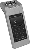
Configure any of your IO Link devices—from sensors to switches—without a PC, outlet, or separate software. Use these programmers to set parameters, check the quality of runs, clone settings for other devices, and more. Whether you’re setting up a device for the first time or adjusting settings, the easy-to-use touchscreen makes for a smooth experience. Since these programmers are powered by a battery and small enough to carry, you can bring them wherever you need.
As soon as you connect your device, these programmers download its IO Device Description (IODD) file. This means you won’t need to manually input device details, saving you time to jump right into programming. Internal storage keeps IODD files and custom settings on hand for you. If you need extra space, insert a microSD card (not included) into these programmers before turning on the connected device.
Plug devices with M8 or M12 connections directly into the sockets on these programmers. If your device has wire leads, use the included adapter.
| Connection Type | Internal Memory Size | Data Connection Type | Features | Environmental Rating | Battery Type | Includes | Specifications Met | Each | |
| A-Code, 3-Pole M8 Socket A-Code, 4-Pole M8 Socket A-Code, 5-Pole M12 Socket | 16 GB | Wi-Fi microSD Card | LED Status Indicator | IP30 | Rechargeable | M12 to 4 Hook Adapter (1 1/2 ft. Lg) USB Charging Cord (1 1/2 ft. Lg) | CE Marked | 0000000 | 000000000 |
DIN-Rail Mount Solid State Interface Relays
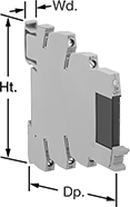
With no moving parts, these solid state relays last longer, switch faster, and are quieter than mechanical relays. They interface between your controller and components to isolate input and output circuits, which protects components from voltage spikes, amplifies the relay’s signal, and reduces interference for reliable transmission. The relay’s LED indicator shines when it’s powered on, so you know at a glance which relays are wired correctly and what the switching position is. These relays are often used for switching small motors and sensors. Rated IP20, they prevent fingers and other objects from touching live circuits.
Mount them on 35 mm DIN rail (also known as DIN 3 rail) with the included socket. Relays disconnect from the socket for easy replacement.
Relays with Relay Socket and Retaining Clip | Replacement Relays | |||||||||||
|---|---|---|---|---|---|---|---|---|---|---|---|---|
| Number of Terminals | Input Voltage | Output Voltage | Control Current, mA | Switching Current @ Voltage | Max. Switching Voltage | Ht. | Wd. | Dp. | Each | Each | ||
1 Circuit Controlled with 1 Off (Normally Open)—SPST-NO | ||||||||||||
With Screw Terminals | ||||||||||||
| 5 | 24V AC, 48V AC, 120V AC, 240V AC, 24V DC, 48V DC, 60V DC, 120V DC, 240V DC | 0-48V DC | 22 | 100 mA @ 48 V DC | 48V DC | 3.5" | 0.2" | 3.4" | 0000000 | 000000 | 0000000 | 000000 |
| 5 | 24V DC | 3-48V DC | 8.5 | 100 mA @ 48 V DC | 48V DC | 3.1" | 0.2" | 3.7" | 0000000 | 00000 | 000000 | 00 |