


Load-Stopping Air Cylinders

Control the movement of loads on your conveyor—the rod on these air cylinders extends to stop loads and retracts to let them pass. While standard air cylinders have a weaker rod that will bend with side impact, these air cylinders have a thick carbon steel rod that won’t bend. The rod is also chrome plated, so it won’t corrode in wet environments.
To activate relays and controllers using these air cylinders, add a sensor (sold separately).
![]() For technical drawings and 3-D models, click on a part number.
For technical drawings and 3-D models, click on a part number.


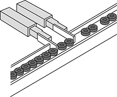
Parts Metering Air Cylinders
Space out parts on your conveyor line or vibratory feeder. Also known as escapements, these air cylinders have at least one finger that extends to hold parts and then retracts to release them. The fingers are built to withstand force from the side, so your part won’t slip past. All fingers have tapped holes on all five of their faces, so you can mount attachments to any side of them.
One-finger cylinders can be spaced as far away from each other as needed, making them the best choice for use with large parts. Create a system of these air cylinders by placing multiple along your line to control the timing and speed with which they meter parts.
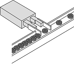
Two-finger cylinders are good for precisely positioning items for sealing, labeling, and inspection. Operating on fixed timing and sequencing, they extend one finger to stop a part then extend the other finger to separate it. The two fingers hold the part like you would between your thumb and index finger. When the part is ready to be released, they retract the first finger while the other finger continues to hold back other parts. Lastly, they retract the other finger to let the next part through.
![]() For technical drawings and 3-D models, click on a part number.
For technical drawings and 3-D models, click on a part number.

Lg. | Air Inlet | ||||||||
|---|---|---|---|---|---|---|---|---|---|
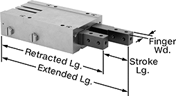
| Stroke | Retracted, mm | Extended, mm | Finger Wd., mm | Sensor Ready | Thread Size | Thread Type | Gender | Each | |
8mm Bore Size (19mm Wd.) | |||||||||
| 10 | 77 | 87 | 6 | Sensor Ready | M3 × 0.5mm | Metric | Female | 0000000 | 0000000 |
| 20 | 97 | 117 | 6 | Sensor Ready | M3 × 0.5mm | Metric | Female | 0000000 | 000000 |
12mm Bore Size (26mm Wd.) | |||||||||
| 10 | 95 | 105 | 8 | Sensor Ready | M5 × 0.8mm | Metric | Female | 0000000 | 000000 |
| 20 | 115 | 135 | 8 | Sensor Ready | M5 × 0.8mm | Metric | Female | 0000000 | 000000 |
| 30 | 135 | 165 | 8 | Sensor Ready | M5 × 0.8mm | Metric | Female | 0000000 | 000000 |
20mm Bore Size (35mm Wd.) | |||||||||
| 10 | 115 | 125 | 11 | Sensor Ready | M5 × 0.8mm | Metric | Female | 0000000 | 000000 |
| 20 | 135 | 155 | 11 | Sensor Ready | M5 × 0.8mm | Metric | Female | 0000000 | 000000 |
| 30 | 155 | 185 | 11 | Sensor Ready | M5 × 0.8mm | Metric | Female | 0000000 | 000000 |
Lg. | Air Inlet | |||||||||
|---|---|---|---|---|---|---|---|---|---|---|
| Stroke | Retracted, mm | Extended, mm | Finger Wd., mm | Jaw Wd., mm | Sensor Ready | Thread Size | Thread Type | Gender | Each | |
8mm Bore Size (34mm Wd.) | ||||||||||
| 8 | 75 | 83 | 6 | 20.3 | Sensor Ready | M3 × 0.5mm | Metric | Female | 0000000 | 0000000 |
12mm Bore Size (44mm Wd.) | ||||||||||
| 12 | 99 | 111 | 8 | 7.6 | Sensor Ready | M5 × 0.8mm | Metric | Female | 0000000 | 000000 |
20mm Bore Size (64mm Wd.) | ||||||||||
| 20 | 135 | 155 | 11 | 14.5 | Sensor Ready | M5 × 0.8mm | Metric | Female | 0000000 | 000000 |
25mm Bore Size (84mm Wd.) | ||||||||||
| 25 | 175 | 200 | 15 | 24.5 | Sensor Ready | M5 × 0.8mm | Metric | Female | 0000000 | 000000 |
Heavy-Duty Load-Stopping Air Cylinders

Stop heavy material in its tracks. With the same footprint as regular load-stopping air cylinders, these air cylinders have a lever end that absorbs 30% more force. Plus, they’re tested to withstand twice as many cycles. Made of carbon steel, the rod extends to stop loads and retracts to let them pass. Even if material jams into the rod from an angle, it won’t bend or snap. Choose them for high-volume lines carrying heavy material, such as pallet conveyors.
To activate relays and controllers using these air cylinders, add a sensor (sold separately).
![]() For technical drawings and 3-D models, click on a part number.
For technical drawings and 3-D models, click on a part number.


Lg., mm | Air Inlet | ||||||||
|---|---|---|---|---|---|---|---|---|---|
| Stroke | Retracted | Extended | Force @ 100 psi, lbs. | Rod Dia., mm | Pipe Size | Thread Type | Gender | Each | |
32 mm Bore Size (46 mm Wd.) | |||||||||
| 20 | 140 | 160 | 120 | 9 | 1/8 | NPT | Female | 0000000 | 0000000 |
50 mm Bore Size (73 mm Wd.) | |||||||||
| 30 | 182.5 | 212.5 | 310 | 11 | 1/8 | NPT | Female | 0000000 | 000000 |
63 mm Bore Size (87.5 mm Wd.) | |||||||||
| 30 | 204.5 | 234.5 | 500 | 13 | 1/4 | NPT | Female | 0000000 | 000000 |
80 mm Bore Size (109 mm Wd.) | |||||||||
| 40 | 252.5 | 292.5 | 700 | 13 | 1/4 | NPT | Female | 0000000 | 000000 |