


About Loc-Line and Snap-Loc Coolant Hose
Assemble and disassemble Loc-Line and Snap-Loc coolant hose by snapping components together or pulling them apart. Assembly and separation tools (sold separately) are recommended.
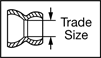
To ensure compatibility, select the color and trade size that match your current system. A system’s trade size is equal to the ID of its hose.
About Air Preparation
More
1/4" Loc-Line Coolant Hose


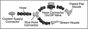
Build a custom system to deliver coolant, cutting oil, water, or air in any direction. Once in position, hose stays put—there's no spring back or movement caused by vibration or heavy flow.
Assemble and disassemble by snapping components together or pulling them apart. Assembly pliers (sold separately) are recommended. To ensure compatibility, select the color and trade size that match your current system. These components fit Loc-Line hose with a 1/4” ID.
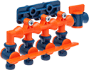
Manifolds can be joined with connectors.
![]() For technical drawings and 3-D models, click on a part number.
For technical drawings and 3-D models, click on a part number.
For styles 31 and 32 manifolds, add style 13 tee-shaped hose connectors.
Inlet Hose Connection | Outlet Hose Connections | O'all | Mounting Holes | ||||||||||||||
|---|---|---|---|---|---|---|---|---|---|---|---|---|---|---|---|---|---|
| Style | No. of | Gender | No. of | Gender | Ht. | Wd. | Dp. | Valve Operation | Material | Max. Flow Rate, gph | Max. Pressure, psi | Max. Temp., °F | No. of | Dia. | Mounting Fasteners Included | Each | |
| 31 | 1 | Female | 4 | Male | 2 15/16" | 5 3/16" | 1 9/16" | Handle | Acetal Plastic | 250 | 50 | 170° | 2 | 1/4" | No | 000000000 | 000000 |
| 32 | 1 | Female | 4 | Male | 1 13/16" | 4 1/4" | 1" | __ | Acetal Plastic | 250 | 30 | 170° | 2 | 1/4" | No | 00000000 | 00000 |
For styles 34 and 35 manifolds, use a style 2 coolant supply connector to connect a style 12 wye-shaped hose connector.
Barbed Tube Inlet Connection | Threaded Pipe Outlet Connections | O'all | ||||||||||||||||
|---|---|---|---|---|---|---|---|---|---|---|---|---|---|---|---|---|---|---|
| Style | No. of | For Tube ID | No. of | Size | Thread Type | Gender | Ht. | Wd. | Lg. | OD | Material | Fitting Material | Max. Flow Rate, gph | Max. Pressure, psi | Max. Temp., °F | Includes | Each | |
| 34 | 1 | 1/2" | 2 | 1/4 | NPT | Female | 2 9/16" | 1 3/16" | 1 7/16" | __ | Aluminum | Brass | 250 | 50 | 335° | One 1/4 NPT Plug | 000000000 | 000000 |
| 35 | 1 | 3/8" | 4 | 1/4 | NPT | Female | 1 3/16" | __ | __ | 2 1/8" | Aluminum | Brass | 250 | 30 | 170° | Three 1/4 NPT Plugs | 00000000 | 00000 |
1/2" Loc-Line Coolant Hose

Build a custom system to deliver coolant, cutting oil, water, or air in any direction. Once in position, hose stays put—there’s no spring back or movement caused by vibration or heavy flow.
Assemble and disassemble by snapping components together or pulling them apart. Assembly pliers (sold separately) are recommended. To ensure compatibility, select the color and trade size that match your current system. These components fit Loc-Line hose with a 1/2" ID.
Manifolds can be joined with connectors.
![]() For technical drawings and 3-D models, click on a part number.
For technical drawings and 3-D models, click on a part number.
For style 29 manifold, add style 9 tee-shaped hose connectors.
Inlet Hose Connection | Outlet Hose Connections | O'all | Mounting Holes | |||||||||||||
|---|---|---|---|---|---|---|---|---|---|---|---|---|---|---|---|---|
| Style | No. of | Gender | No. of | Gender | Ht. | Wd. | Dp. | Material | Max. Flow Rate, gph | Max. Pressure, psi | Max. Temp., °F | No. of | Dia. | Mounting Fasteners Included | Each | |
| 29 | 1 | Female | 4 | Male | 2 1/8" | 6" | 1 1/4" | Acetal Plastic | 478 | 20 | 170° | 2 | 1/4" | No | 00000000 | 000000 |
1/2" Snap-Loc Coolant Hose

Build a custom system to deliver coolant, cutting oil, water, or air in any direction. Once in position, hose stays put—there’s no spring back or movement caused by vibration or heavy flow.
Assemble and disassemble by snapping components together or pulling them apart. Assembly and separation tools (sold separately) are recommended. To ensure compatibility, select the color and trade size that match your current system. These components fit Snap-Loc hose with a 1/2" ID.
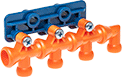
Manifolds can be joined with connectors.
![]() For technical drawings and 3-D models, click on a part number.
For technical drawings and 3-D models, click on a part number.
For style 15 manifold, use a style 2 or 3 coolant supply connector to connect a style 10 wye-shaped hose connector.
Threaded Pipe Inlet Connection | Threaded Pipe Outlet Connections | O'all | Mounting Holes | |||||||||||||||
|---|---|---|---|---|---|---|---|---|---|---|---|---|---|---|---|---|---|---|
| Style | Size (No. of) | Thread Type | Gender | Size (No. of) | Thread Type | Gender | Ht. | Wd. | Dp. | Material | Max. Flow Rate, gph | Max. Pressure, psi | Max. Temp., °F | No. of | Dia. | Mounting Fasteners Included | Each | |
| 15 | 1/2 (1) | NPT | Female | 3/8 (3), 1/2 (1) | NPT | Female | 1 3/4" | 5 1/2" | 1" | Acetal Plastic | 480 | 19 | 200° | 4 | 1/4" | No | 0000000 | 000000 |
Norgren Modular Compressed Air Regulator Manifolds

Connect two or more of these manifold regulators to meet multiple pressure requirements from a single air supply—set a different output pressure with each regulator. Each regulator has two regulated outlets and one unregulated outlet. Regulators are relieving style, so they exhaust when the downstream pressure exceeds the set pressure. Install in your air line after filters.
Mounting brackets (sold separately) allow you to attach manifold regulators to a wall or equipment.
Joiner clamps (sold separately) connect manifold regulators to each other and other Norgren modular components with the same series number. They come with mounting brackets.
End block sets (sold separately) allow you to swap out filter/regulator/lubricator components without unthreading your air line connections. The blocks remain connected to your pipe while you replace components between them.
Regulator Manifolds | ||||||||||||||
|---|---|---|---|---|---|---|---|---|---|---|---|---|---|---|
Overall | Joiner Clamps | End Block Sets | ||||||||||||
| Manufacturer Series | Inlet Pipe Size | Outlet Pipe Size (No. of Outlets) | Max. Flow Rate | Max. Pressure, psi | Wd. | Ht. | Max. Temp., °F | Choose a Pressure Regulating Range, psi | Each | Each | Each | |||
Zinc Housing | ||||||||||||||
Series No. 72—NPT Female Inlet and Outlets | ||||||||||||||
| R72 | 1/4 | 1/4 (1 Unregulated), 1/4 (1 Regulated), 1/8 (1 Regulated) | 83 cfm @ 100 psi | 300 | 2" | 4 1/4" | 150° | 000000 | 000000 | 000000 | 000000 | 0000000 | 000000 | |
| R72 | 3/8 | 3/8 (1 Unregulated), 1/4 (1 Regulated), 1/8 (1 Regulated) | 83 cfm @ 100 psi | 300 | 2" | 4 1/4" | 150° | 000000 | 00000 | 000000 | 00000 | 0000000 | 00000 | |
Aluminum Housing | ||||||||||||||
Series No. 74—NPT Female Inlet and Outlets | ||||||||||||||
| R74 | 1/2 | 1/2 (1 Unregulated), 1/2 (1 Regulated), 1/8 (1 Regulated) | 160 scfm @ 100 psi | 300 | 3 1/8" | 6 5/8" | 175° | 5-150 | 00000000 | 000000 | 000000 | 00000 | 0000000 | 00000 |
| R74 | 3/4 | 3/4 (1 Unregulated), 1/2 (1 Regulated), 1/8 (1 Regulated) | 160 scfm @ 100 psi | 300 | 3 1/8" | 6 5/8" | 175° | 5-150 | 00000000 | 000000 | 000000 | 00000 | 0000000 | 00000 |
Wilkerson Modular Compressed Air Regulator Manifolds

Connect two or more of these manifold regulators to meet multiple pressure requirements from a single air supply—set a different output pressure with each regulator. Each regulator has two regulated outlets, one unregulated outlet, and an additional port that can be used for a pressure gauge. Regulators are relieving style, so they exhaust when the downstream pressure exceeds the set pressure. Install in your air line after filters.
Joiner clamps (sold separately) connect manifold regulators to each other and other Wilkerson modular components with the same series number. They come with mounting brackets to attach the regulator to a wall or equipment.
End block sets (sold separately) allow you to swap out filter/regulator/lubricator components without unthreading your air line connections. The blocks remain connected to your pipe while you replace components between them.
Gauges are not included with Series No. 19 manifold regulators.
![]() For technical drawings and 3-D models, click on a part number.
For technical drawings and 3-D models, click on a part number.
Regulator Manifolds | |||||||||||||||
|---|---|---|---|---|---|---|---|---|---|---|---|---|---|---|---|
Overall | Joiner Clamps | End Block Sets | |||||||||||||
| Manufacturer Series | Inlet Pipe Size | Outlet Pipe Size (No. of Outlets) | Max. Flow Rate | Max. Pressure, psi | Gauge Included | Wd. | Ht. | Max. Temp., °F | Choose a Pressure Regulating Range, psi | Each | Each | Each | |||
Aluminum Housing | |||||||||||||||
Series No. 19—NPT Female Inlet and Outlets | |||||||||||||||
| R19 | 1/4 | 1/4 (1 Unregulated), 1/4 (2 Regulated) | 62 scfm @ 100 psi | 300 | No | 2 3/8" | 5 1/2" | 150° | 0000000 | 000000 | 00000000 | 000000 | 0000000 | 000000 | |
| R19 | 3/8 | 3/8 (1 Unregulated), 1/4 (2 Regulated) | 62 scfm @ 100 psi | 300 | No | 2 3/8" | 5 1/2" | 150° | 0000000 | 00000 | 00000000 | 00000 | 00000000 | 00000 | |
| R19 | 1/2 | 1/2 (1 Unregulated), 1/4 (2 Regulated) | 62 scfm @ 100 psi | 300 | No | 2 3/8" | 5 1/2" | 150° | 0000000 | 00000 | 00000000 | 00000 | 00000000 | 00000 | |