


About Linear Bearings
More
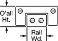
Low-Friction Telescoping Slides
Use these slides for short-travel, high-speed applications where low-friction performance is a must. They have a bearing cage that eliminates ball collisions to extend service life.
Travel length is the total distance the carriage travels in both directions. For example, a slide with a 6" travel length travels 3" in each direction.
Note: Capacities listed are for horizontal mounting. If side mounted, load capacities are cut in half.
![]() For technical drawings and 3-D models, click on a part number.
For technical drawings and 3-D models, click on a part number.
Carriage Mounting | Rail Mounting | ||||||||||||
|---|---|---|---|---|---|---|---|---|---|---|---|---|---|
| Rail Lg. | Rail Ht. | Travel Lg. | Dynamic Load Cap., lbs. | Carriage Wd. | O'all Ht. | Max. Temp., °F | No. of Holes | Hole Thread Size | No. of Holes | For Fastener Thread Size | Mounting Fasteners Included | Each | |
Aluminum Carriage and Rail | |||||||||||||
0.16" Rail Wd. | |||||||||||||
| 0.75" | 0.14" | 0.5" | 2 | 0.38" | 0.23" | 180° | 4 | 2-56 | 2 | 2-56 | No | 0000000 | 0000000 |
| 1.25" | 0.14" | 1" | 2 | 0.38" | 0.23" | 180° | 4 | 2-56 | 2 | 2-56 | No | 0000000 | 000000 |
1/4" Rail Wd. | |||||||||||||
| 1.06" | 0.19" | 0.5" | 4 | 0.56" | 0.32" | 180° | 4 | 2-56 | 2 | 2-56 | No | 0000000 | 000000 |
| 2.06" | 0.19" | 1" | 8 | 0.56" | 0.32" | 180° | 4 | 2-56 | 2 | 2-56 | No | 0000000 | 000000 |
| 3.06" | 0.19" | 2" | 12 | 0.56" | 0.32" | 180° | 4 | 2-56 | 2 | 2-56 | No | 0000000 | 000000 |
| 5.06" | 0.19" | 4" | 16 | 0.56" | 0.32" | 180° | 4 | 2-56 | 2 | 2-56 | No | 000000 | 000000 |
| 6.06" | 0.19" | 5" | 18 | 0.56" | 0.32" | 180° | 4 | 2-56 | 2 | 2-56 | No | 000000 | 000000 |
0.38" Rail Wd. | |||||||||||||
| 1.06" | 0.25" | 0.5" | 8 | 0.75" | 0.41" | 180° | 4 | 4-40 | 2 | 4-40 | No | 0000000 | 000000 |
| 2.06" | 0.25" | 1" | 10 | 0.75" | 0.41" | 180° | 4 | 4-40 | 2 | 4-40 | No | 0000000 | 000000 |
| 3.06" | 0.25" | 2" | 12 | 0.75" | 0.41" | 180° | 4 | 4-40 | 2 | 4-40 | No | 0000000 | 000000 |
| 4.06" | 0.25" | 3" | 14 | 0.75" | 0.41" | 180° | 4 | 4-40 | 2 | 4-40 | No | 0000000 | 000000 |
1/2" Rail Wd. | |||||||||||||
| 1.56" | 0.31" | 0.75" | 15 | 1.06" | 0.53" | 180° | 4 | 6-32 | 2 | 6-32 | No | 0000000 | 000000 |
| 2.56" | 0.31" | 1.5" | 18 | 1.06" | 0.53" | 180° | 4 | 6-32 | 2 | 6-32 | No | 0000000 | 000000 |
| 3.56" | 0.31" | 2" | 20 | 1.06" | 0.53" | 180° | 4 | 6-32 | 2 | 6-32 | No | 0000000 | 000000 |
| 4.56" | 0.31" | 3" | 25 | 1.06" | 0.53" | 180° | 4 | 6-32 | 2 | 6-32 | No | 0000000 | 000000 |
| 6" | 0.31" | 4" | 30 | 1.06" | 0.53" | 180° | 4 | 6-32 | 2 | 6-32 | No | 000000 | 000000 |
| 8" | 0.31" | 6" | 35 | 1.06" | 0.53" | 180° | 4 | 6-32 | 2 | 6-32 | No | 000000 | 000000 |
| 10" | 0.31" | 8" | 40 | 1.06" | 0.53" | 180° | 4 | 6-32 | 2 | 6-32 | No | 000000 | 000000 |
3/4" Rail Wd. | |||||||||||||
| 2" | 0.34" | 1" | 15 | 1.5" | 0.62" | 180° | 4 | 6-32 | 2 | 6-32 | No | 000000 | 000000 |
0.88" Rail Wd. | |||||||||||||
| 1.75" | 0.4" | 1" | 25 | 1.75" | 0.75" | 150° | 8 | 6-32 | 2 | 6-32 | No | 0000000 | 000000 |
| 2.75" | 0.4" | 1.5" | 30 | 1.75" | 0.75" | 180° | 4 | 6-32 | 2 | 6-32 | No | 000000 | 000000 |
| 3" | 0.4" | 2" | 40 | 1.75" | 0.75" | 150° | 12 | 6-32 | 2 | 6-32 | No | 0000000 | 000000 |
| 4" | 0.4" | 3" | 55 | 1.75" | 0.75" | 150° | 16 | 6-32 | 2 | 6-32 | No | 0000000 | 000000 |
0.94" Rail Wd. | |||||||||||||
| 9" | 0.69" | 6" | 150 | 2.62" | 1" | 150° | 8 | 10-32 | 3 | 1/4"-20 | No | 0000000 | 00000000 |
1.48" Rail Wd. | |||||||||||||
| 2.62" | 0.61" | 1" | 60 | 2.62" | 1" | 150° | 8 | 10-32 | 2 | 1/4"-20 | No | 0000000 | 000000 |
| 4" | 0.61" | 2" | 85 | 2.62" | 1" | 150° | 6 | 10-32 | 4 | 1/4"-20 | No | 0000000 | 000000 |
| 5" | 0.61" | 3" | 100 | 2.62" | 1" | 150° | 6 | 10-32 | 4 | 1/4"-20 | No | 0000000 | 000000 |
| 6" | 0.61" | 4" | 120 | 2.62" | 1" | 150° | 10 | 10-32 | 4 | 1/4"-20 | No | 0000000 | 000000 |
1 1/2" Rail Wd. | |||||||||||||
| 8" | 0.63" | 5" | 130 | 2.62" | 1" | 180° | 4 | 10-32 | 2 | 10-32 | No | 000000 | 000000 |
Carriage Mounting | Rail Mounting | ||||||||||||
|---|---|---|---|---|---|---|---|---|---|---|---|---|---|
| Rail Lg., mm | Rail Ht., mm | Travel Lg., mm | Dynamic Load Cap., lbs. | Carriage Wd., mm | O'all Ht., mm | Max. Temp., °F | No. of Holes | Hole Thread Size | No. of Holes | For Fastener Thread Size | Mounting Fasteners Included | Each | |
Aluminum Carriage and Rail | |||||||||||||
4 mm Rail Wd. | |||||||||||||
| 13 | 3.4 | 8 | 1 | 9.7 | 5.8 | 180° | 4 | M2 | 2 | M2 | No | 00000000 | 0000000 |
6.4 mm Rail Wd. | |||||||||||||
| 52 | 4.7 | 25 | 8 | 14.2 | 8 | 180° | 4 | M2 | 2 | M2 | No | 00000000 | 000000 |
| 78 | 4.7 | 50 | 11 | 14.2 | 8 | 180° | 4 | M2 | 2 | M2 | No | 00000000 | 000000 |
9.5 mm Rail Wd. | |||||||||||||
| 27 | 6.3 | 13 | 8 | 19 | 10.4 | 180° | 4 | M3 | 2 | M3 | No | 00000000 | 000000 |
| 52 | 6.3 | 25 | 11 | 19 | 10.4 | 180° | 4 | M3 | 2 | M3 | No | 00000000 | 000000 |
12.7 mm Rail Wd. | |||||||||||||
| 40 | 7.9 | 19 | 15 | 26.9 | 13.4 | 180° | 4 | M4 | 2 | M4 | No | 00000000 | 000000 |
| 90 | 7.9 | 50 | 19 | 26.9 | 13.4 | 180° | 4 | M4 | 2 | M4 | No | 00000000 | 000000 |
| 152 | 7.9 | 100 | 30 | 26.9 | 13.4 | 180° | 4 | M4 | 2 | M4 | No | 00000000 | 000000 |
| 203 | 7.9 | 150 | 35 | 26.9 | 13.4 | 180° | 4 | M4 | 2 | M4 | No | 00000000 | 000000 |
19 mm Rail Wd. | |||||||||||||
| 51 | 8.6 | 25 | 15 | 38 | 15.8 | 180° | 4 | M4 | 2 | M4 | No | 00000000 | 000000 |
22.2 mm Rail Wd. | |||||||||||||
| 70 | 10.2 | 38 | 30 | 44 | 19 | 180° | 4 | M4 | 2 | M4 | No | 00000000 | 000000 |
High-Load Low-Friction Telescoping Slides

With a row of crossed-roller bearings on each side of the rail, these slides have over twice the load capacity of standard low-friction slides and are better for handling shock loads. Use them for short-travel, high-speed applications where low-friction performance is a must.
Travel length is the total distance the carriage travels in both directions. For example, a slide with a 6" travel length travels 3" in each direction.
Note: Capacities listed are for horizontal mounting. If side mounted, load capacities are cut in half.
![]() For technical drawings and 3-D models, click on a part number.
For technical drawings and 3-D models, click on a part number.
Carriage Mounting | Rail Mounting | ||||||||||||
|---|---|---|---|---|---|---|---|---|---|---|---|---|---|
| Rail Lg. | Rail Ht. | Travel Lg. | Dynamic Load Cap., lbs. | Carriage Wd. | O'all Ht. | Max. Temp., °F | No. of Holes | Hole Thread Size | No. of Holes | For Fastener Thread Size | Mounting Fasteners Included | Each | |
Aluminum Carriage and Rail | |||||||||||||
1/4" Rail Wd. | |||||||||||||
| 1.06" | 0.19" | 0.5" | 30 | 0.56" | 0.32" | 180° | 4 | 2-56 | 2 | 2-56 | No | 0000000 | 0000000 |
0.38" Rail Wd. | |||||||||||||
| 1.06" | 0.25" | 0.5" | 45 | 0.75" | 0.41" | 180° | 4 | 4-40 | 2 | 4-40 | No | 0000000 | 000000 |
| 2.06" | 0.25" | 1" | 75 | 0.75" | 0.41" | 180° | 4 | 4-40 | 2 | 4-40 | No | 0000000 | 000000 |
1/2" Rail Wd. | |||||||||||||
| 1.56" | 0.31" | 0.75" | 110 | 1.06" | 0.53" | 180° | 4 | 6-32 | 2 | 6-32 | No | 0000000 | 000000 |
| 2.56" | 0.31" | 1.5" | 130 | 1.06" | 0.53" | 180° | 4 | 6-32 | 2 | 6-32 | No | 0000000 | 000000 |
| 3.56" | 0.31" | 2" | 220 | 1.06" | 0.53" | 180° | 4 | 6-32 | 2 | 6-32 | No | 0000000 | 000000 |
| 4.56" | 0.31" | 3" | 260 | 1.06" | 0.53" | 180° | 4 | 6-32 | 2 | 6-32 | No | 0000000 | 000000 |
| 6" | 0.31" | 4" | 280 | 1.06" | 0.53" | 180° | 4 | 6-32 | 2 | 6-32 | No | 000000 | 000000 |
| 8" | 0.31" | 6" | 290 | 1.06" | 0.53" | 180° | 4 | 6-32 | 2 | 6-32 | No | 000000 | 000000 |
| 10" | 0.31" | 8" | 320 | 1.06" | 0.53" | 180° | 4 | 6-32 | 2 | 6-32 | No | 000000 | 000000 |
Carriage Mounting | Rail Mounting | ||||||||||||
|---|---|---|---|---|---|---|---|---|---|---|---|---|---|
| Rail Lg., mm | Rail Ht., mm | Travel Lg., mm | Dynamic Load Cap., lbs. | Carriage Wd., mm | O'all Ht., mm | Max. Temp., °F | No. of Holes | Hole Thread Size | No. of Holes | For Fastener Thread Size | Mounting Fasteners Included | Each | |
Aluminum Carriage and Rail | |||||||||||||
6.4 mm Rail Wd. | |||||||||||||
| 27 | 4.7 | 13 | 30 | 14.2 | 8 | 240° | 4 | M2 | 2 | M2 | No | 0000000 | 0000000 |
9.5 mm Rail Wd. | |||||||||||||
| 27 | 6.3 | 13 | 45 | 19 | 10 | 240° | 4 | M3 | 2 | M3 | No | 0000000 | 000000 |
| 52 | 6.3 | 25 | 75 | 19 | 10 | 240° | 4 | M3 | 2 | M3 | No | 0000000 | 000000 |
| 78 | 6.3 | 50 | 90 | 19 | 10 | 240° | 4 | M3 | 2 | M3 | No | 0000000 | 000000 |
| 103 | 6.3 | 75 | 95 | 19 | 10 | 240° | 4 | M3 | 2 | M3 | No | 0000000 | 000000 |
12.7 mm Rail Wd. | |||||||||||||
| 40 | 7.9 | 19 | 110 | 26.9 | 13 | 240° | 4 | M4 | 2 | M4 | No | 0000000 | 000000 |
| 65 | 7.9 | 38 | 130 | 26.9 | 13 | 240° | 4 | M4 | 2 | M4 | No | 0000000 | 000000 |
| 90 | 7.9 | 50 | 220 | 26.9 | 13 | 240° | 4 | M4 | 2 | M4 | No | 0000000 | 000000 |
| 116 | 7.9 | 75 | 260 | 26.9 | 13 | 240° | 4 | M4 | 2 | M4 | No | 0000000 | 000000 |
Light Duty Track Roller Carriages and Guide Rails


Nylon rollers provide low-friction movement for light loads and corrosive environments. The V-shaped profile of the rollers and rails prevents debris from becoming trapped on the rail. Wipers sweep away dust and contaminants and distribute lubricant along the rail. Carriages can be adjusted for a snug or loose fit on the rail (also known as preload). Mount in any orientation without affecting load capacity.
Guide rails require a support rail (sold separately) for carriage clearance. Order one per guide rail.
![]() For technical drawings and 3-D models, click on a part number.
For technical drawings and 3-D models, click on a part number.
Track Roller Carriages and Guide Rails

V-shaped rollers and rails allow these carriages to operate well in dirty environments because the debris won't get trapped on the rail. Wipers sweep away dust and contaminants and distribute lubricant along the rail. Carriages can be adjusted for a snug or loose fit on the rail (also known as preload). Mount in any orientation without affecting load capacity.
0.516" wide guide rails require a support rail (sold separately) for carriage clearance. Order one per guide rail.
![]() For technical drawings and 3-D models, click on a part number.
For technical drawings and 3-D models, click on a part number.
External Retaining Rings

Open these rings, pass them over the end of a shaft, and release to spring into the groove. Ring ID is measured with the ring uninstalled. Use retaining ring pliers (sold separately) to install and remove rings.
1060-1090 spring steel rings are an economical choice with good strength. A black-phosphate finish is mildly corrosion resistant in dry environments.
DIN 1.4122 stainless steel rings withstand wear caused by abrasion, similar to 400 series stainless steel. They also resist corrosion in wet environments.
Beryllium copper rings conduct electricity and have excellent corrosion resistance. Do not use beryllium copper rings in direct contact with acetylene.
Thrust load capacity, also known as PR, is based on using a shaft that is harder than the ring.
![]() For technical drawings and 3-D models, click on a part number.
For technical drawings and 3-D models, click on a part number.
For Groove | Ring | ||||||||||
|---|---|---|---|---|---|---|---|---|---|---|---|
| For OD | Dia. | Wd. | ID | Thick. | Min. Hardness | Thrust Load Capacity, lbs. | Magnetic Properties | Specifications Met | Pkg. Qty. | Pkg. | |
Beryllium Copper | |||||||||||
| 1/8" | 0.117" | 0.012" | 0.112" | 0.01" | Rockwell C36 | 110 | Nonmagnetic | ASME B18.27.1 | 100 | 000000000 | 000000 |
| 5/32" | 0.146" | 0.012" | 0.142" | 0.01" | Rockwell C34 | 132 | Nonmagnetic | ASTM B197 | 100 | 000000000 | 00000 |
| 3/16" | 0.175" | 0.018" | 0.168" | 0.015" | Rockwell C36 | 240 | Nonmagnetic | ASME B18.27.1 | 100 | 000000000 | 00000 |
| 7/32" | 0.205" | 0.018" | 0.196" | 0.015" | Rockwell C36 | 280 | Nonmagnetic | ASME B18.27.1 | 25 | 000000000 | 0000 |
| 15/64" | 0.222" | 0.018" | 0.215" | 0.015" | Rockwell C36 | 310 | Nonmagnetic | ASME B18.27.1 | 25 | 000000000 | 0000 |
| 1/4" | 0.23" | 0.029" | 0.225" | 0.025" | Rockwell C36 | 440 | Nonmagnetic | ASME B18.27.1 | 25 | 000000000 | 00000 |
| 5/16" | 0.29" | 0.029" | 0.281" | 0.025" | Rockwell C36 | 560 | Nonmagnetic | ASME B18.27.1 | 10 | 000000000 | 0000 |
| 3/8" | 0.352" | 0.029" | 0.338" | 0.025" | Rockwell C36 | 660 | Nonmagnetic | ASME B18.27.1 | 10 | 000000000 | 0000 |
| 7/16" | 0.412" | 0.029" | 0.395" | 0.025" | Rockwell C36 | 770 | Nonmagnetic | ASME B18.27.1 | 10 | 000000000 | 0000 |
| 1/2" | 0.468" | 0.039" | 0.461" | 0.035" | Rockwell C36 | 1,250 | Nonmagnetic | ASME B18.27.1 | 10 | 000000000 | 00000 |
| 5/8" | 0.588" | 0.039" | 0.579" | 0.035" | Rockwell C36 | 1,560 | Nonmagnetic | ASME B18.27.1 | 5 | 000000000 | 0000 |
| 3/4" | 0.704" | 0.046" | 0.693" | 0.042" | Rockwell C36 | 2,810 | Nonmagnetic | ASME B18.27.1 | 5 | 000000000 | 00000 |
| 7/8" | 0.821" | 0.046" | 0.81" | 0.042" | Rockwell C36 | 3,270 | Nonmagnetic | ASME B18.27.1 | 1 | 000000000 | 0000 |
| 1" | 0.94" | 0.046" | 0.925" | 0.042" | Rockwell C36 | 3,760 | Nonmagnetic | ASME B18.27.1 | 1 | 000000000 | 0000 |
| 1 1/4" | 1.176" | 0.056" | 1.156" | 0.05" | Rockwell C36 | 5,590 | Nonmagnetic | ASME B18.27.1 | 1 | 000000000 | 0000 |
For Groove | Ring | ||||||||||
|---|---|---|---|---|---|---|---|---|---|---|---|
| For OD, mm | Dia., mm | Wd., mm | ID, mm | Thick., mm | Min. Hardness | Thrust Load Capacity, lbs. | Magnetic Properties | Specifications Met | Pkg. Qty. | Pkg. | |
Black-Phosphate 1060-1090 Spring Steel | |||||||||||
| 3 | 2.8 | 0.5 | 2.7 | 0.4 | Rockwell C44 | 100 | Magnetic | DIN 471 | 100 | 000000000 | 00000 |
| 4 | 3.8 | 0.5 | 3.7 | 0.4 | Rockwell C44 | 110 | Magnetic | DIN 471 | 100 | 000000000 | 0000 |
| 5 | 4.8 | 0.7 | 4.7 | 0.6 | Rockwell C44 | 220 | Magnetic | DIN 471 | 100 | 000000000 | 0000 |
| 6 | 5.7 | 0.8 | 5.6 | 0.7 | Rockwell C44 | 320 | Magnetic | DIN 471 | 100 | 000000000 | 0000 |
| 7 | 6.7 | 0.9 | 6.5 | 0.8 | Rockwell C44 | 580 | Magnetic | DIN 471 | 100 | 000000000 | 00000 |
| 8 | 7.6 | 0.9 | 7.4 | 0.8 | Rockwell C44 | 670 | Magnetic | DIN 471 | 100 | 000000000 | 00000 |
| 9 | 8.6 | 1.1 | 8.4 | 1 | Rockwell C44 | 780 | Magnetic | DIN 471 | 100 | 000000000 | 00000 |
| 10 | 9.6 | 1.1 | 9.3 | 1 | Rockwell C44 | 890 | Magnetic | DIN 471 | 100 | 000000000 | 0000 |
| 11 | 10.5 | 1.1 | 10.2 | 1 | Rockwell C44 | 1,010 | Magnetic | DIN 471 | 100 | 000000000 | 00000 |
| 12 | 11.5 | 1.1 | 11 | 1 | Rockwell C44 | 1,120 | Magnetic | DIN 471 | 100 | 000000000 | 00000 |
| 13 | 12.4 | 1.1 | 11.9 | 1 | Rockwell C44 | 1,300 | Magnetic | DIN 471 | 100 | 000000000 | 00000 |
| 14 | 13.4 | 1.1 | 12.9 | 1 | Rockwell C44 | 1,430 | Magnetic | DIN 471 | 100 | 000000000 | 00000 |
| 15 | 14.3 | 1.1 | 13.8 | 1 | Rockwell C44 | 1,550 | Magnetic | DIN 471 | 100 | 000000000 | 00000 |
| 16 | 15.2 | 1.1 | 14.7 | 1 | Rockwell C44 | 1,660 | Magnetic | DIN 471 | 100 | 000000000 | 00000 |
| 17 | 16.2 | 1.1 | 15.7 | 1 | Rockwell C44 | 1,790 | Magnetic | DIN 471 | 50 | 000000000 | 0000 |
| 18 | 17 | 1.3 | 16.5 | 1.2 | Rockwell C44 | 3,820 | Magnetic | DIN 471 | 50 | 000000000 | 00000 |
| 19 | 18 | 1.3 | 17.5 | 1.2 | Rockwell C44 | 3,820 | Magnetic | DIN 471 | 50 | 000000000 | 00000 |
| 20 | 19 | 1.3 | 18.5 | 1.2 | Rockwell C44 | 3,840 | Magnetic | DIN 471 | 50 | 000000000 | 00000 |
| 21 | 20 | 1.3 | 19.5 | 1.2 | Rockwell C44 | 3,770 | Magnetic | DIN 471 | 25 | 000000000 | 0000 |
| 22 | 21 | 1.3 | 20.5 | 1.2 | Rockwell C44 | 3,790 | Magnetic | DIN 471 | 25 | 000000000 | 0000 |
| 23 | 22 | 1.3 | 21.5 | 1.2 | Rockwell C44 | 3,730 | Magnetic | DIN 471 | 25 | 000000000 | 00000 |
| 24 | 22.9 | 1.3 | 22.2 | 1.2 | Rockwell C44 | 3,610 | Magnetic | DIN 471 | 25 | 000000000 | 0000 |
| 25 | 23.9 | 1.3 | 23.2 | 1.2 | Rockwell C44 | 3,640 | Magnetic | DIN 471 | 25 | 000000000 | 0000 |
| 26 | 24.9 | 1.3 | 24.2 | 1.2 | Rockwell C44 | 3,610 | Magnetic | DIN 471 | 25 | 000000000 | 00000 |
| 27 | 25.6 | 1.3 | 24.9 | 1.2 | Rockwell C44 | 3,680 | Magnetic | DIN 471 | 10 | 000000000 | 0000 |
| 28 | 26.6 | 1.6 | 25.9 | 1.5 | Rockwell C44 | 7,210 | Magnetic | DIN 471 | 10 | 000000000 | 0000 |
| 29 | 27.6 | 1.6 | 26.9 | 1.5 | Rockwell C44 | 7,140 | Magnetic | DIN 471 | 10 | 000000000 | 00000 |
| 30 | 28.6 | 1.6 | 27.9 | 1.5 | Rockwell C44 | 7,210 | Magnetic | DIN 471 | 10 | 000000000 | 00000 |
| 32 | 30.3 | 1.6 | 29.6 | 1.5 | Rockwell C44 | 7,010 | Magnetic | DIN 471 | 10 | 000000000 | 00000 |
| 34 | 32.3 | 1.6 | 31.5 | 1.5 | Rockwell C44 | 7,030 | Magnetic | DIN 471 | 10 | 000000000 | 00000 |
| 35 | 33 | 1.6 | 32.2 | 1.5 | Rockwell C44 | 6,920 | Magnetic | DIN 471 | 10 | 000000000 | 00000 |
| 36 | 34 | 1.85 | 33.2 | 1.75 | Rockwell C44 | 11,100 | Magnetic | DIN 471 | 10 | 000000000 | 00000 |
| 38 | 36 | 1.85 | 35.2 | 1.75 | Rockwell C44 | 11,100 | Magnetic | DIN 471 | 10 | 000000000 | 00000 |
| 40 | 37.5 | 1.85 | 36.5 | 1.75 | Rockwell C44 | 11,400 | Magnetic | DIN 471 | 5 | 000000000 | 00000 |
| 45 | 42.5 | 1.85 | 41.5 | 1.75 | Rockwell C44 | 11,000 | Magnetic | DIN 471 | 5 | 000000000 | 00000 |
| 50 | 47 | 2.15 | 45.8 | 2 | Rockwell C44 | 16,400 | Magnetic | DIN 471 | 5 | 000000000 | 00000 |
| 55 | 52 | 2.15 | 50.8 | 2 | Rockwell C44 | 16,000 | Magnetic | DIN 471 | 1 | 000000000 | 0000 |
| 60 | 57 | 2.15 | 55.8 | 2 | Rockwell C44 | 15,500 | Magnetic | DIN 471 | 1 | 000000000 | 0000 |
| 65 | 62 | 2.65 | 60.8 | 2.5 | Rockwell C44 | 30,300 | Magnetic | DIN 471 | 1 | 000000000 | 0000 |
| 70 | 67 | 2.65 | 65.5 | 2.5 | Rockwell C44 | 30,100 | Magnetic | DIN 471 | 1 | 000000000 | 0000 |
| 75 | 72 | 2.65 | 70.5 | 2.5 | Rockwell C44 | 29,200 | Magnetic | DIN 471 | 1 | 000000000 | 0000 |
| 80 | 76.5 | 2.65 | 74.5 | 2.5 | Rockwell C44 | 28,700 | Magnetic | DIN 471 | 1 | 000000000 | 0000 |
| 85 | 81.5 | 3.15 | 79.5 | 3 | Rockwell C44 | 48,300 | Magnetic | DIN 471 | 1 | 000000000 | 0000 |
| 90 | 86.5 | 3.15 | 84.5 | 3 | Rockwell C44 | 48,700 | Magnetic | DIN 471 | 1 | 000000000 | 0000 |
| 95 | 91.5 | 3.15 | 89.5 | 3 | Rockwell C44 | 47,600 | Magnetic | DIN 471 | 1 | 000000000 | 00000 |
| 100 | 96.5 | 3.15 | 94.5 | 3 | Rockwell C44 | 108,000 | Magnetic | DIN 471 | 1 | 000000000 | 00000 |
| 110 | 106 | 4.15 | 103 | 4 | Rockwell C44 | 102,000 | Magnetic | DIN 471 | 1 | 000000000 | 0000 |
| 120 | 116 | 4.15 | 113 | 4 | Rockwell C44 | 95,300 | Magnetic | DIN 471 | 1 | 000000000 | 00000 |
| 130 | 126 | 4.15 | 123 | 4 | Rockwell C44 | 88,800 | Magnetic | DIN 471 | 1 | 000000000 | 00000 |
| 140 | 136 | 4.15 | 133 | 4 | Rockwell C44 | 84,500 | Magnetic | DIN 471 | 1 | 000000000 | 00000 |
| 150 | 145 | 4.15 | 142 | 4 | Rockwell C44 | 80,200 | Magnetic | DIN 471 | 1 | 000000000 | 00000 |
| 160 | 155 | 4.15 | 151 | 4 | Rockwell C44 | 78,400 | Magnetic | DIN 471 | 1 | 000000000 | 00000 |
| 170 | 165 | 4.15 | 160.5 | 4 | Rockwell C44 | 78,400 | Magnetic | DIN 471 | 1 | 000000000 | 00000 |
| 180 | 175 | 4.15 | 170.5 | 4 | Rockwell C44 | 77,500 | Magnetic | DIN 471 | 1 | 000000000 | 00000 |
| 190 | 185 | 4.15 | 180.5 | 4 | Rockwell C44 | 74,800 | Magnetic | DIN 471 | 1 | 000000000 | 00000 |
| 200 | 195 | 4.15 | 190.5 | 4 | Rockwell C44 | 71,700 | Magnetic | DIN 471 | 1 | 000000000 | 00000 |
DIN 1.4122 Stainless Steel | |||||||||||
| 5 | 4.8 | 0.7 | 4.7 | 0.6 | Rockwell C47 | 220 | Magnetic | DIN 471 | 5 | 000000000 | 00000 |
| 6 | 5.7 | 0.8 | 5.6 | 0.7 | Rockwell C47 | 320 | Magnetic | DIN 471 | 10 | 000000000 | 0000 |
| 7 | 6.7 | 0.9 | 6.5 | 0.8 | Rockwell C47 | 580 | Magnetic | DIN 471 | 10 | 000000000 | 0000 |
| 8 | 7.6 | 0.9 | 7.4 | 0.8 | Rockwell C47 | 670 | Magnetic | DIN 471 | 10 | 000000000 | 0000 |
| 9 | 8.6 | 1.1 | 8.4 | 1 | Rockwell C47 | 780 | Magnetic | DIN 471 | 10 | 000000000 | 00000 |
| 10 | 9.6 | 1.1 | 9.3 | 1 | Rockwell C47 | 890 | Magnetic | DIN 471 | 5 | 000000000 | 0000 |
| 11 | 10.5 | 1.1 | 10.2 | 1 | Rockwell C47 | 1,010 | Magnetic | DIN 471 | 5 | 000000000 | 0000 |
| 12 | 11.5 | 1.1 | 11 | 1 | Rockwell C47 | 1,120 | Magnetic | DIN 471 | 5 | 000000000 | 0000 |
| 13 | 12.4 | 1.1 | 11.9 | 1 | Rockwell C47 | 1,300 | Magnetic | DIN 471 | 5 | 000000000 | 0000 |
| 14 | 13.4 | 1.1 | 12.9 | 1 | Rockwell C47 | 1,430 | Magnetic | DIN 471 | 5 | 000000000 | 0000 |
| 15 | 14.3 | 1.1 | 13.8 | 1 | Rockwell C47 | 1,550 | Magnetic | DIN 471 | 5 | 000000000 | 0000 |
| 16 | 15.2 | 1.1 | 14.7 | 1 | Rockwell C47 | 1,660 | Magnetic | DIN 471 | 5 | 000000000 | 0000 |
| 17 | 16.2 | 1.1 | 15.7 | 1 | Rockwell C47 | 1,790 | Magnetic | DIN 471 | 5 | 000000000 | 0000 |
| 18 | 17 | 1.3 | 16.5 | 1.2 | Rockwell C47 | 3,820 | Magnetic | DIN 471 | 5 | 000000000 | 0000 |
| 19 | 18 | 1.3 | 17.5 | 1.2 | Rockwell C47 | 3,820 | Magnetic | DIN 471 | 5 | 000000000 | 0000 |
| 20 | 19 | 1.3 | 18.5 | 1.2 | Rockwell C47 | 3,840 | Magnetic | DIN 471 | 5 | 000000000 | 0000 |
| 21 | 20 | 1.3 | 19.5 | 1.2 | Rockwell C47 | 3,770 | Magnetic | DIN 471 | 5 | 000000000 | 00000 |
| 22 | 21 | 1.3 | 20.5 | 1.2 | Rockwell C47 | 3,790 | Magnetic | DIN 471 | 5 | 000000000 | 00000 |
| 23 | 22 | 1.3 | 21.5 | 1.2 | Rockwell C47 | 3,730 | Magnetic | DIN 471 | 5 | 000000000 | 00000 |
| 24 | 22.9 | 1.3 | 22.2 | 1.2 | Rockwell C47 | 3,610 | Magnetic | DIN 471 | 5 | 000000000 | 00000 |
| 25 | 23.9 | 1.3 | 23.2 | 1.2 | Rockwell C47 | 3,640 | Magnetic | DIN 471 | 5 | 000000000 | 00000 |
| 26 | 24.9 | 1.3 | 24.2 | 1.2 | Rockwell C47 | 3,610 | Magnetic | DIN 471 | 1 | 000000000 | 0000 |
| 27 | 25.6 | 1.3 | 24.9 | 1.2 | Rockwell C47 | 3,680 | Magnetic | DIN 471 | 1 | 000000000 | 0000 |
| 28 | 26.6 | 1.6 | 25.9 | 1.5 | Rockwell C47 | 7,210 | Magnetic | DIN 471 | 1 | 000000000 | 0000 |
| 29 | 27.6 | 1.6 | 26.9 | 1.5 | Rockwell C47 | 7,140 | Magnetic | DIN 471 | 1 | 000000000 | 0000 |
| 30 | 28.6 | 1.6 | 27.9 | 1.5 | Rockwell C47 | 7,210 | Magnetic | DIN 471 | 1 | 000000000 | 0000 |
| 32 | 30.3 | 1.6 | 29.6 | 1.5 | Rockwell C47 | 7,010 | Magnetic | DIN 471 | 1 | 000000000 | 0000 |
| 34 | 32.3 | 1.6 | 31.5 | 1.5 | Rockwell C47 | 7,030 | Magnetic | DIN 471 | 1 | 000000000 | 0000 |
| 35 | 33 | 1.6 | 32.2 | 1.5 | Rockwell C47 | 6,920 | Magnetic | DIN 471 | 1 | 000000000 | 0000 |
| 36 | 34 | 1.9 | 33.2 | 1.75 | Rockwell C47 | 11,100 | Magnetic | DIN 471 | 1 | 000000000 | 0000 |
| 38 | 36 | 1.9 | 35.2 | 1.75 | Rockwell C47 | 11,100 | Magnetic | DIN 471 | 1 | 000000000 | 0000 |
| 40 | 37.5 | 1.9 | 36.5 | 1.75 | Rockwell C47 | 11,400 | Magnetic | DIN 471 | 1 | 000000000 | 0000 |
| 45 | 42.5 | 1.9 | 41.5 | 1.75 | Rockwell C47 | 11,000 | Magnetic | DIN 471 | 1 | 000000000 | 0000 |
| 50 | 47 | 2.15 | 45.8 | 2 | Rockwell C47 | 16,400 | Magnetic | DIN 471 | 1 | 000000000 | 0000 |
| 55 | 52 | 2.15 | 50.8 | 2 | Rockwell C47 | 16,000 | Magnetic | DIN 471 | 1 | 000000000 | 0000 |
| 60 | 57 | 2.15 | 55.8 | 2 | Rockwell C47 | 15,500 | Magnetic | DIN 471 | 1 | 000000000 | 0000 |
| 65 | 62 | 2.65 | 60.8 | 2.5 | Rockwell C47 | 30,300 | Magnetic | DIN 471 | 1 | 000000000 | 0000 |
| 70 | 67 | 2.65 | 65.5 | 2.5 | Rockwell C47 | 30,100 | Magnetic | DIN 471 | 1 | 000000000 | 00000 |
| 75 | 72 | 2.65 | 70.5 | 2.5 | Rockwell C47 | 29,200 | Magnetic | DIN 471 | 1 | 000000000 | 00000 |
| 80 | 76.5 | 2.65 | 74.5 | 2.5 | Rockwell C47 | 28,700 | Magnetic | DIN 471 | 1 | 000000000 | 00000 |
Low-Clearance External Retaining Rings

Also known as constant-section rings, these rings have open ends and a profile that does not taper like other external retaining rings. Use them with linear bearings on support rail shafts. Open rings with flat-tip retaining ring pliers (sold separately), pass them over the end of a shaft, and release to spring into the groove. The black-phosphate finish is mildly corrosion resistant in dry environments.
![]() For technical drawings and 3-D models, click on a part number.
For technical drawings and 3-D models, click on a part number.
For Groove | Ring | ||||||
|---|---|---|---|---|---|---|---|
| For OD | Dia. | Wd. | OD | Thick. | Magnetic Properties | Each | |
Black-Phosphate Steel | |||||||
| 1/2" | 0.474" | 0.039" | 0.55" | 0.035" | Magnetic | 0000000 | 00000 |
| 5/8" | 0.596" | 0.039" | 0.673" | 0.035" | Magnetic | 0000000 | 0000 |
| 7/8" | 0.82" | 0.046" | 0.923" | 0.042" | Magnetic | 0000000 | 0000 |
| 1 1/8" | 1.07" | 0.056" | 1.18" | 0.05" | Magnetic | 0000000 | 0000 |
| 1 1/4" | 1.178" | 0.056" | 1.301" | 0.05" | Magnetic | 0000000 | 0000 |
| 1 9/16" | 1.47" | 0.068" | 1.62" | 0.062" | Magnetic | 0000000 | 0000 |
| 2" | 1.89" | 0.068" | 2.04" | 0.062" | Magnetic | 0000000 | 0000 |
| 2 3/8" | 2.245" | 0.086" | 2.448" | 0.078" | Magnetic | 0000000 | 0000 |
| 8 1/2" Lg. Steel Flat-Tip Retaining Ring Pliers | 0000000 | Each | 000000 |
High-Temperature Linear Ball Bearings for Support Rail Shafts

The choice for low-friction motion in high-temperature environments. Mount these bearings on a support rail shaft for applications requiring maximum rigidity. They have a fixed-alignment design for applications where shaft misalignment is unlikely. To install, slide bearings into a housing (not included) and secure in place with two retaining rings (sold separately).
![]() For technical drawings and 3-D models, click on a part number.
For technical drawings and 3-D models, click on a part number.
Bearings | External Retaining Rings | ||||||||||
|---|---|---|---|---|---|---|---|---|---|---|---|
| For Shaft Dia. | Overall Lg. | Wd. | For Housing ID | Retaining Ring Groove End-to-End Lg. | Dynamic Load Capacity, lbs. | Max. Temperature, ° F | For Shaft Material | Each | Each | ||
Steel Bearings | |||||||||||
| 1/2" | 1 1/4" | 5/16" | 0.8740" - 0.8760" | 0.97" | 60 | 500° | Stainless Steel, Steel | 0000000 | 000000 | 0000000 | 00000 |
| 3/4" | 1 5/8" | 7/16" | 1.2490" - 1.2510" | 1.17" | 140 | 500° | Stainless Steel, Steel | 0000000 | 00000 | 0000000 | 0000 |
| 1" | 2 1/4" | 9/16" | 1.5615" - 1.5635" | 1.76" | 240 | 500° | Stainless Steel, Steel | 0000000 | 000000 | 0000000 | 0000 |
Bearings | |||||||||||||
|---|---|---|---|---|---|---|---|---|---|---|---|---|---|
Load Capacity, lbs. | External Retaining Rings | ||||||||||||
| For Shaft Dia., mm | Overall Lg., mm | Wd., mm | For Housing ID, mm | Retaining Ring Groove End-to-End Lg., mm | Dynamic | Static | Temperature Range, ° F | For Shaft Material | Each | Pkg. Qty. | Pkg. | ||
Steel Bearings | |||||||||||||
| 12 | 30 | 8 | 21.000 - 21.021 | 23 | 110 | 175 | -4° to 230° | Stainless Steel, Steel | 00000000 | 000000 | 25 | 000000000 | 00000 |