


Filter by
For Use With
Set Pressure
Maximum Inlet Pressure
Outlet Pressure
Set Pressure Configuration
Maximum Pressure
Inlet Connection
DFARS Specialty Metals
Thread Type
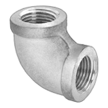
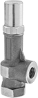
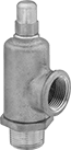
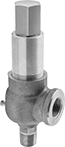
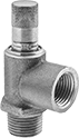
Precision-Adjustment Pressure-Relief Valves for Fuel
NPT Male Inlet and NPT Female Relief Port
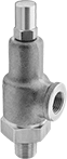 |
Bronze Body—Valves with a bronze body are harder and more durable than valves with a brass body for a longer service life.
Inlet | Relief | ||||||||||||||||||||||||||||||||||||||||||||||||||||||||||||||||||||||||||||||||||||||||||||||||||
|---|---|---|---|---|---|---|---|---|---|---|---|---|---|---|---|---|---|---|---|---|---|---|---|---|---|---|---|---|---|---|---|---|---|---|---|---|---|---|---|---|---|---|---|---|---|---|---|---|---|---|---|---|---|---|---|---|---|---|---|---|---|---|---|---|---|---|---|---|---|---|---|---|---|---|---|---|---|---|---|---|---|---|---|---|---|---|---|---|---|---|---|---|---|---|---|---|---|---|---|
Pipe Size | Location | Max. Pressure, psi | Port Pipe Size | Port Location | Set Pressure Adjustment Method | Shape | Overall Ht. | For Use With | Temp. Range, ° F | Valve Type | Choose a Set Pressure, psi | Each | |||||||||||||||||||||||||||||||||||||||||||||||||||||||||||||||||||||||||||||||||||||||
Brass Body—Brass Seal | |||||||||||||||||||||||||||||||||||||||||||||||||||||||||||||||||||||||||||||||||||||||||||||||||||
| 1/2 | Bottom | 400 | 1/2 | Side | External Adjustment Screw | 90° Elbow | 5 7/8" | Diesel Fuel, Fuel Oil, Gasoline, Kerosene | -60 to 450 | Relief | 0 to 14 , 15 to 25 , 26 to 40 , 41 to 75 , 76 to 110 , 111 to 130 , 131 to 150 , 151 to 200 , 201 to 400 | 4703K54 | 0000000 | ||||||||||||||||||||||||||||||||||||||||||||||||||||||||||||||||||||||||||||||||||||||
| 3/4 | Bottom | 400 | 3/4 | Side | External Adjustment Screw | 90° Elbow | 6 1/4" | Diesel Fuel, Fuel Oil, Gasoline, Kerosene | -60 to 450 | Relief | 0 to 14 , 15 to 25 , 26 to 40 , 41 to 75 , 76 to 110 , 111 to 130 , 131 to 150 , 151 to 200 , 201 to 400 | 4703K55 | 000000 | ||||||||||||||||||||||||||||||||||||||||||||||||||||||||||||||||||||||||||||||||||||||
Bronze Body—Bronze Seal | |||||||||||||||||||||||||||||||||||||||||||||||||||||||||||||||||||||||||||||||||||||||||||||||||||
| 1 | Bottom | 400 | 1 | Side | External Adjustment Screw | 90° Elbow | 7 1/2" | Diesel Fuel, Fuel Oil, Gasoline, Kerosene | -60 to 450 | Relief | 0 to 14 , 15 to 25 , 26 to 40 , 41 to 75 , 76 to 110 , 111 to 130 , 131 to 150 , 151 to 200 , 201 to 400 | 4703K56 | 000000 | ||||||||||||||||||||||||||||||||||||||||||||||||||||||||||||||||||||||||||||||||||||||
| 1 1/4 | Bottom | 400 | 1 1/4 | Side | External Adjustment Screw | 90° Elbow | 8 1/4" | Diesel Fuel, Fuel Oil, Gasoline, Kerosene | -60 to 450 | Relief | 0 to 14 , 15 to 25 , 26 to 40 , 41 to 75 , 76 to 110 , 111 to 130 , 131 to 150 , 151 to 200 , 201 to 400 | 4703K57 | 000000 | ||||||||||||||||||||||||||||||||||||||||||||||||||||||||||||||||||||||||||||||||||||||
| 1 1/2 | Bottom | 400 | 1 1/2 | Side | External Adjustment Screw | 90° Elbow | 9 1/2" | Diesel Fuel, Fuel Oil, Gasoline, Kerosene | -60 to 450 | Relief | 0 to 14 , 15 to 25 , 26 to 40 , 41 to 75 , 76 to 110 , 111 to 130 , 131 to 150 , 151 to 200 , 201 to 400 | 4703K58 | 000000 | ||||||||||||||||||||||||||||||||||||||||||||||||||||||||||||||||||||||||||||||||||||||
| 2 | Bottom | 400 | 2 | Side | External Adjustment Screw | 90° Elbow | 10 7/8" | Diesel Fuel, Fuel Oil, Gasoline, Kerosene | -60 to 450 | Relief | 0 to 14 , 15 to 25 , 26 to 40 , 41 to 75 , 76 to 110 , 111 to 130 , 131 to 150 , 151 to 200 , 201 to 400 | 4703K59 | 000000 | ||||||||||||||||||||||||||||||||||||||||||||||||||||||||||||||||||||||||||||||||||||||
| 3 | Bottom | 300 | 3 | Side | External Adjustment Screw | 90° Elbow | 13 3/16" | Diesel Fuel, Fuel Oil, Gasoline, Kerosene | -60 to 450 | Relief | 0 to 14 , 15 to 25 , 26 to 40 , 41 to 75 , 76 to 110 , 111 to 130 , 131 to 150 , 151 to 200 , 201 to 300 | 4703K62 | 00000000 | ||||||||||||||||||||||||||||||||||||||||||||||||||||||||||||||||||||||||||||||||||||||
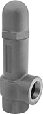
Adjustable Pressure-Relief Valves for Fuel
NPT Female Inlet and Relief Port
 |
Inlet | Relief | ||||||||||||||||||||||||||||||||||||||||||||||||||||||||||||||||||||||||||||||||||||||||||||||||||
|---|---|---|---|---|---|---|---|---|---|---|---|---|---|---|---|---|---|---|---|---|---|---|---|---|---|---|---|---|---|---|---|---|---|---|---|---|---|---|---|---|---|---|---|---|---|---|---|---|---|---|---|---|---|---|---|---|---|---|---|---|---|---|---|---|---|---|---|---|---|---|---|---|---|---|---|---|---|---|---|---|---|---|---|---|---|---|---|---|---|---|---|---|---|---|---|---|---|---|---|
Pipe Size | Location | Max. Pressure, psi | Port Pipe Size | Port Location | Set Pressure Adjustment Method | Shape | Overall Ht. | For Use With | Temp. Range, ° F | Valve Type | Choose a Set Pressure, psi | Each | |||||||||||||||||||||||||||||||||||||||||||||||||||||||||||||||||||||||||||||||||||||||
Brass Body—416 Stainless Steel Seal | |||||||||||||||||||||||||||||||||||||||||||||||||||||||||||||||||||||||||||||||||||||||||||||||||||
| 3/8 | Bottom | 1,000 | 3/8 | Side | External Adjustment Screw | 90° Elbow | 5 3/8" | Diesel Fuel, Fuel Oil, Gasoline, Kerosene | -20 to 400 | Relief | 3 to 10 , 7 to 35 , 30 to 100 , 60 to 175 , 150 to 350 , 300 to 500 | 7844K51 | 0000000 | ||||||||||||||||||||||||||||||||||||||||||||||||||||||||||||||||||||||||||||||||||||||
| 1/2 | Bottom | 1,000 | 1/2 | Side | External Adjustment Screw | 90° Elbow | 6 3/16" | Diesel Fuel, Fuel Oil, Gasoline, Kerosene | -20 to 400 | Relief | 3 to 10 , 7 to 35 , 30 to 100 , 60 to 175 , 150 to 350 , 300 to 500 | 7844K52 | 000000 | ||||||||||||||||||||||||||||||||||||||||||||||||||||||||||||||||||||||||||||||||||||||
| 3/4 | Bottom | 1,000 | 3/4 | Side | External Adjustment Screw | 90° Elbow | 6 15/16" | Diesel Fuel, Fuel Oil, Gasoline, Kerosene | -20 to 400 | Relief | 3 to 10 , 7 to 35 , 30 to 100 , 60 to 175 , 150 to 350 , 300 to 500 | 7844K53 | 000000 | ||||||||||||||||||||||||||||||||||||||||||||||||||||||||||||||||||||||||||||||||||||||
| 1 | Bottom | 1,000 | 1 | Side | External Adjustment Screw | 90° Elbow | 8 1/4" | Diesel Fuel, Fuel Oil, Gasoline, Kerosene | -20 to 400 | Relief | 3 to 10 , 7 to 35 , 30 to 100 , 60 to 175 , 150 to 350 , 300 to 500 | 7844K54 | 000000 | ||||||||||||||||||||||||||||||||||||||||||||||||||||||||||||||||||||||||||||||||||||||
| 1 1/4 | Bottom | 1,000 | 1 1/4 | Side | External Adjustment Screw | 90° Elbow | 9 9/16" | Diesel Fuel, Fuel Oil, Gasoline, Kerosene | -20 to 400 | Relief | 3 to 10 , 7 to 35 , 30 to 100 , 60 to 175 , 150 to 350 , 300 to 500 | 7844K55 | 000000 | ||||||||||||||||||||||||||||||||||||||||||||||||||||||||||||||||||||||||||||||||||||||
| 1 1/2 | Bottom | 1,000 | 1 1/2 | Side | External Adjustment Screw | 90° Elbow | 11 1/16" | Diesel Fuel, Fuel Oil, Gasoline, Kerosene | -20 to 400 | Relief | 3 to 10 , 7 to 35 , 30 to 100 , 60 to 175 , 150 to 350 , 300 to 500 | 7844K56 | 000000 | ||||||||||||||||||||||||||||||||||||||||||||||||||||||||||||||||||||||||||||||||||||||
| 2 | Bottom | 1,000 | 2 | Side | External Adjustment Screw | 90° Elbow | 13" | Diesel Fuel, Fuel Oil, Gasoline, Kerosene | -20 to 400 | Relief | 3 to 10 , 7 to 35 , 30 to 100 , 60 to 175 , 150 to 350 , 250 to 600 | 7844K57 | 00000000 | ||||||||||||||||||||||||||||||||||||||||||||||||||||||||||||||||||||||||||||||||||||||
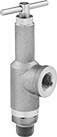
Adjustable Pressure-Relief Valves for Water
NPT Male Inlet and NPT Female Relief Port
 | 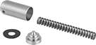 |
Valve | Repair Kit |
Valves | Repair Kits | ||||||||||||||||||||||||||||||||||||||||||||||||||||||||||||||||||||||||||||||||||||||||||||||||||
|---|---|---|---|---|---|---|---|---|---|---|---|---|---|---|---|---|---|---|---|---|---|---|---|---|---|---|---|---|---|---|---|---|---|---|---|---|---|---|---|---|---|---|---|---|---|---|---|---|---|---|---|---|---|---|---|---|---|---|---|---|---|---|---|---|---|---|---|---|---|---|---|---|---|---|---|---|---|---|---|---|---|---|---|---|---|---|---|---|---|---|---|---|---|---|---|---|---|---|---|
Inlet | Relief | Set Pressure | |||||||||||||||||||||||||||||||||||||||||||||||||||||||||||||||||||||||||||||||||||||||||||||||||
Pipe Size | Location | Max. Pressure, psi | Port Pipe Size | Port Location | Range, psi | Adjustment Method | Shape | Features | Overall Ht. | For Use With | Temp. Range, ° F | Valve Type | Each | Each | |||||||||||||||||||||||||||||||||||||||||||||||||||||||||||||||||||||||||||||||||||||
Brass Body—Buna-N Seal | |||||||||||||||||||||||||||||||||||||||||||||||||||||||||||||||||||||||||||||||||||||||||||||||||||
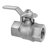
| 1/4 | Bottom | 50 | 1/4 | Side | 0 to 50 | T-Handle | 90° Elbow | Locknut, Removable Bonnet | 4" | Water | -30 to 160 | Relief | 9763K711 | 0000000 | ——— | 0 | |||||||||||||||||||||||||||||||||||||||||||||||||||||||||||||||||||||||||||||||||||
| 1/4 | Bottom | 150 | 1/4 | Side | 0 to 150 | T-Handle | 90° Elbow | Locknut, Removable Bonnet | 4" | Water | -30 to 160 | Relief | 9763K712 | 000000 | ——— | 0 | |||||||||||||||||||||||||||||||||||||||||||||||||||||||||||||||||||||||||||||||||||
| 1/4 | Bottom | 300 | 1/4 | Side | 0 to 300 | T-Handle | 90° Elbow | Locknut, Removable Bonnet | 4" | Water | -30 to 160 | Relief | 9763K713 | 000000 | ——— | 0 | |||||||||||||||||||||||||||||||||||||||||||||||||||||||||||||||||||||||||||||||||||
| 1/4 | Bottom | 700 | 1/4 | Side | 0 to 700 | T-Handle | 90° Elbow | Locknut, Removable Bonnet | 4" | Water | -30 to 160 | Relief | 9763K714 | 000000 | ——— | 0 | |||||||||||||||||||||||||||||||||||||||||||||||||||||||||||||||||||||||||||||||||||
| 1/4 | Bottom | 1,000 | 1/4 | Side | 0 to 1,000 | T-Handle | 90° Elbow | Locknut, Removable Bonnet | 4" | Water | -30 to 160 | Relief | 9763K75 | 000000 | ——— | 0 | |||||||||||||||||||||||||||||||||||||||||||||||||||||||||||||||||||||||||||||||||||
| 3/8 | Bottom | 150 | 3/8 | Side | 0 to 150 | T-Handle | 90° Elbow | Locknut, Removable Bonnet | 4" | Water | -30 to 160 | Relief | 9763K911 | 000000 | ——— | 0 | |||||||||||||||||||||||||||||||||||||||||||||||||||||||||||||||||||||||||||||||||||
| 3/8 | Bottom | 300 | 3/8 | Side | 0 to 300 | T-Handle | 90° Elbow | Locknut, Removable Bonnet | 4" | Water | -30 to 160 | Relief | 9763K912 | 000000 | ——— | 0 | |||||||||||||||||||||||||||||||||||||||||||||||||||||||||||||||||||||||||||||||||||
| 3/8 | Bottom | 700 | 3/8 | Side | 0 to 700 | T-Handle | 90° Elbow | Locknut, Removable Bonnet | 4" | Water | -30 to 160 | Relief | 9763K913 | 000000 | ——— | 0 | |||||||||||||||||||||||||||||||||||||||||||||||||||||||||||||||||||||||||||||||||||
| 3/8 | Bottom | 1,000 | 3/8 | Side | 0 to 1,000 | T-Handle | 90° Elbow | Locknut, Removable Bonnet | 4" | Water | -30 to 160 | Relief | 9763K76 | 000000 | ——— | 0 | |||||||||||||||||||||||||||||||||||||||||||||||||||||||||||||||||||||||||||||||||||
| 3/8 | Bottom | 1,200 | 3/8 | Side | 0 to 1,200 | T-Handle | 90° Elbow | Locknut, Removable Bonnet | 4" | Water | -30 to 160 | Relief | 9763K77 | 000000 | ——— | 0 | |||||||||||||||||||||||||||||||||||||||||||||||||||||||||||||||||||||||||||||||||||
| 1/2 | Bottom | 50 | 1/2 | Side | 0 to 50 | T-Handle | 90° Elbow | Locknut | 6 5/8" | Water | -30 to 160 | Relief | 9763K49 | 00000 | 9763K78 | 000000 | |||||||||||||||||||||||||||||||||||||||||||||||||||||||||||||||||||||||||||||||||||
| 1/2 | Bottom | 300 | 1/2 | Side | 0 to 300 | T-Handle | 90° Elbow | Locknut | 6 5/8" | Water | -30 to 160 | Relief | 9763K51 | 00000 | 9763K72 | 00000 | |||||||||||||||||||||||||||||||||||||||||||||||||||||||||||||||||||||||||||||||||||
| 1/2 | Bottom | 700 | 1/2 | Side | 0 to 700 | T-Handle | 90° Elbow | Locknut | 6 5/8" | Water | -30 to 160 | Relief | 9763K53 | 00000 | 9763K73 | 00000 | |||||||||||||||||||||||||||||||||||||||||||||||||||||||||||||||||||||||||||||||||||
| 1/2 | Bottom | 1,200 | 1/2 | Side | 0 to 1,200 | T-Handle | 90° Elbow | Locknut | 6 5/8" | Water | -30 to 160 | Relief | 9763K55 | 000000 | 9763K74 | 00000 | |||||||||||||||||||||||||||||||||||||||||||||||||||||||||||||||||||||||||||||||||||
| 3/4 | Bottom | 50 | 3/4 | Side | 0 to 50 | T-Handle | 90° Elbow | Locknut | 6 5/8" | Water | -30 to 160 | Relief | 9763K59 | 00000 | 9763K78 | 00000 | |||||||||||||||||||||||||||||||||||||||||||||||||||||||||||||||||||||||||||||||||||
| 3/4 | Bottom | 300 | 3/4 | Side | 0 to 300 | T-Handle | 90° Elbow | Locknut | 6 5/8" | Water | -30 to 160 | Relief | 9763K61 | 00000 | 9763K72 | 00000 | |||||||||||||||||||||||||||||||||||||||||||||||||||||||||||||||||||||||||||||||||||
| 3/4 | Bottom | 700 | 3/4 | Side | 0 to 700 | T-Handle | 90° Elbow | Locknut | 6 5/8" | Water | -30 to 160 | Relief | 9763K63 | 00000 | 9763K73 | 00000 | |||||||||||||||||||||||||||||||||||||||||||||||||||||||||||||||||||||||||||||||||||
| 3/4 | Bottom | 1,200 | 3/4 | Side | 0 to 1,200 | T-Handle | 90° Elbow | Locknut | 6 5/8" | Water | -30 to 160 | Relief | 9763K65 | 000000 | 9763K74 | 00000 | |||||||||||||||||||||||||||||||||||||||||||||||||||||||||||||||||||||||||||||||||||
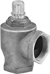
Pressure-Relief Valves for Water
NPT Female Inlet and Relief Port
 |
Inlet | Relief | ||||||||||||||||||||||||||||||||||||||||||||||||||||||||||||||||||||||||||||||||||||||||||||||||||
|---|---|---|---|---|---|---|---|---|---|---|---|---|---|---|---|---|---|---|---|---|---|---|---|---|---|---|---|---|---|---|---|---|---|---|---|---|---|---|---|---|---|---|---|---|---|---|---|---|---|---|---|---|---|---|---|---|---|---|---|---|---|---|---|---|---|---|---|---|---|---|---|---|---|---|---|---|---|---|---|---|---|---|---|---|---|---|---|---|---|---|---|---|---|---|---|---|---|---|---|
Pipe Size | Location | Max. Pressure, psi | Port Pipe Size | Port Location | Shape | Overall Ht. | For Use With | Temp. Range, ° F | Valve Type | Choose a Set Pressure, psi | Each | ||||||||||||||||||||||||||||||||||||||||||||||||||||||||||||||||||||||||||||||||||||||||
Brass Body—Rubber Seal | |||||||||||||||||||||||||||||||||||||||||||||||||||||||||||||||||||||||||||||||||||||||||||||||||||
| 2 | Bottom | 120 | 2 | Side | 90° Elbow | 6 9/16" | Water | 33 to 180 | Relief | 30 , 65 | 4780K16 | 0000000 | |||||||||||||||||||||||||||||||||||||||||||||||||||||||||||||||||||||||||||||||||||||||
NPT Male Inlet and NPT Female Relief Port
 |
Inlet | Relief | ||||||||||||||||||||||||||||||||||||||||||||||||||||||||||||||||||||||||||||||||||||||||||||||||||
|---|---|---|---|---|---|---|---|---|---|---|---|---|---|---|---|---|---|---|---|---|---|---|---|---|---|---|---|---|---|---|---|---|---|---|---|---|---|---|---|---|---|---|---|---|---|---|---|---|---|---|---|---|---|---|---|---|---|---|---|---|---|---|---|---|---|---|---|---|---|---|---|---|---|---|---|---|---|---|---|---|---|---|---|---|---|---|---|---|---|---|---|---|---|---|---|---|---|---|---|
Pipe Size | Location | Max. Pressure, psi | Port Pipe Size | Port Location | Shape | Overall Ht. | For Use With | Temp. Range, ° F | Valve Type | Choose a Set Pressure, psi | Each | ||||||||||||||||||||||||||||||||||||||||||||||||||||||||||||||||||||||||||||||||||||||||
Brass Body—Rubber Seal | |||||||||||||||||||||||||||||||||||||||||||||||||||||||||||||||||||||||||||||||||||||||||||||||||||
| 1/2 | Bottom | 120 | 1/2 | Side | 90° Elbow | 4 3/16" | Water | 33 to 180 | Relief | 30 , 75 | 4780K11 | 0000000 | |||||||||||||||||||||||||||||||||||||||||||||||||||||||||||||||||||||||||||||||||||||||
| 3/4 | Bottom | 120 | 3/4 | Side | 90° Elbow | 4 11/16" | Water | 33 to 180 | Relief | 30 , 75 | 4780K12 | 000000 | |||||||||||||||||||||||||||||||||||||||||||||||||||||||||||||||||||||||||||||||||||||||
| 1 | Bottom | 120 | 1 | Side | 90° Elbow | 5 11/16" | Water | 33 to 180 | Relief | 30 , 75 | 4780K13 | 000000 | |||||||||||||||||||||||||||||||||||||||||||||||||||||||||||||||||||||||||||||||||||||||
| 1 1/4 | Bottom | 120 | 1 1/4 | Side | 90° Elbow | 6 1/16" | Water | 33 to 180 | Relief | 30 , 65 | 4780K14 | 000000 | |||||||||||||||||||||||||||||||||||||||||||||||||||||||||||||||||||||||||||||||||||||||
Hydraulic Pressure-Relief Valves
 |  |
Iron | 316 Stainless Steel |
To set the pressure, unscrew the cap and turn the adjustment screw. Valves begin opening at the set pressure and fully open at about 10% over the set pressure. They begin closing as pressure drops and close when the system pressure is restored below the set pressure.
Iron Body—Iron valves absorb vibration to reduce noise and wear in the pipeline.
316 Stainless Steel Body—316 stainless steel valves are more corrosion resistant than iron valves.
Inlet Connection | Relief Connection | Overall | |||||||||||||||||||||||||||||||||||||||||||||||||||||||||||||||||||||||||||||||||||||||||||||||||
|---|---|---|---|---|---|---|---|---|---|---|---|---|---|---|---|---|---|---|---|---|---|---|---|---|---|---|---|---|---|---|---|---|---|---|---|---|---|---|---|---|---|---|---|---|---|---|---|---|---|---|---|---|---|---|---|---|---|---|---|---|---|---|---|---|---|---|---|---|---|---|---|---|---|---|---|---|---|---|---|---|---|---|---|---|---|---|---|---|---|---|---|---|---|---|---|---|---|---|---|
Pipe Size | Dash Size | Pipe Size | Dash Size | Lg. | Wd. | Ht. | Temp. Range, ° F | Choose a Set Pressure, psi | Each | ||||||||||||||||||||||||||||||||||||||||||||||||||||||||||||||||||||||||||||||||||||||||||
NPT Female Inlet and NPT Female Relief Port | |||||||||||||||||||||||||||||||||||||||||||||||||||||||||||||||||||||||||||||||||||||||||||||||||||
Iron Body | |||||||||||||||||||||||||||||||||||||||||||||||||||||||||||||||||||||||||||||||||||||||||||||||||||
| 3/8 | 06 | 3/8 | 06 | 2 1/16" | 1 3/8" | 5 3/8" | -20 to 400 | 3 to 10 , 7 to 35 , 30 to 100 , 60 to 175 , 150 to 350 , 300 to 500 | 4704K32 | 0000000 | |||||||||||||||||||||||||||||||||||||||||||||||||||||||||||||||||||||||||||||||||||||||||
| 1/2 | 08 | 1/2 | 08 | 2 3/16" | 1 7/16" | 6 3/16" | -20 to 400 | 3 to 10 , 7 to 35 , 30 to 100 , 60 to 175 , 150 to 350 , 300 to 500 | 4704K11 | 000000 | |||||||||||||||||||||||||||||||||||||||||||||||||||||||||||||||||||||||||||||||||||||||||
| 3/4 | 12 | 3/4 | 12 | 2 11/16" | 1 11/16" | 6 15/16" | -20 to 400 | 3 to 10 , 7 to 35 , 30 to 100 , 60 to 175 , 150 to 350 , 300 to 500 | 4704K12 | 000000 | |||||||||||||||||||||||||||||||||||||||||||||||||||||||||||||||||||||||||||||||||||||||||
| 1 | 16 | 1 | 16 | 3 5/16" | 2 1/16" | 8 1/4" | -20 to 400 | 3 to 10 , 7 to 35 , 30 to 100 , 60 to 175 , 150 to 350 , 300 to 500 | 4704K13 | 000000 | |||||||||||||||||||||||||||||||||||||||||||||||||||||||||||||||||||||||||||||||||||||||||
| 1 1/4 | 20 | 1 1/4 | 20 | 3 13/16" | 2 1/2" | 9 9/16" | -20 to 400 | 3 to 10 , 7 to 35 , 30 to 100 , 60 to 175 , 150 to 350 , 300 to 500 | 4704K14 | 000000 | |||||||||||||||||||||||||||||||||||||||||||||||||||||||||||||||||||||||||||||||||||||||||
| 1 1/2 | 24 | 1 1/2 | 24 | 4 1/8" | 2 7/8" | 11 1/16" | -20 to 400 | 3 to 10 , 7 to 35 , 30 to 100 , 60 to 175 , 150 to 350 , 300 to 500 | 4704K25 | 000000 | |||||||||||||||||||||||||||||||||||||||||||||||||||||||||||||||||||||||||||||||||||||||||
| 2 | 32 | 2 | 32 | 4 5/8" | 3 1/4" | 13" | -20 to 400 | 3 to 10 , 7 to 35 , 30 to 100 , 60 to 175 , 150 to 350 , 250 to 600 | 4704K26 | 000000 | |||||||||||||||||||||||||||||||||||||||||||||||||||||||||||||||||||||||||||||||||||||||||
NPT Male Inlet and NPT Female Relief Port | |||||||||||||||||||||||||||||||||||||||||||||||||||||||||||||||||||||||||||||||||||||||||||||||||||
316 Stainless Steel Body | |||||||||||||||||||||||||||||||||||||||||||||||||||||||||||||||||||||||||||||||||||||||||||||||||||
| 1/2 | 08 | 1/2 | 08 | 1 5/8" | 1 1/8" | 4 3/16" | 40 to 250 | 30 to 100 , 101 to 400 , 401 to 1,000 , 1,001 to 2,000 | 5027K11 | 000000 | |||||||||||||||||||||||||||||||||||||||||||||||||||||||||||||||||||||||||||||||||||||||||
Made-to-Order Pressure-Relief Valves
NPT Female Inlet and Relief Port
 |
For Use With—To Order: Please specify medium and a set pressure in 1 psi increments from the range listed in the table.
Inlet | Relief | ||||||||||||||||||||||||||||||||||||||||||||||||||||||||||||||||||||||||||||||||||||||||||||||||||
|---|---|---|---|---|---|---|---|---|---|---|---|---|---|---|---|---|---|---|---|---|---|---|---|---|---|---|---|---|---|---|---|---|---|---|---|---|---|---|---|---|---|---|---|---|---|---|---|---|---|---|---|---|---|---|---|---|---|---|---|---|---|---|---|---|---|---|---|---|---|---|---|---|---|---|---|---|---|---|---|---|---|---|---|---|---|---|---|---|---|---|---|---|---|---|---|---|---|---|---|
Pipe Size | Location | Max. Pressure, psi | Port Pipe Size | Port Location | Choose a Set Pressure, psi | Shape | Overall Ht. | Temp. Range, ° F | Valve Type | For Use With | Each | ||||||||||||||||||||||||||||||||||||||||||||||||||||||||||||||||||||||||||||||||||||||||
316 Stainless Steel Body—Fluoroelastomer Seal | |||||||||||||||||||||||||||||||||||||||||||||||||||||||||||||||||||||||||||||||||||||||||||||||||||
| 1/2 | Bottom | 3,300 | 3/4 | Side | 150 to 2,699 | 90° Elbow | 7 1/2" | -10 to 400 | Relief | Diesel Fuel , Fuel Oil , Gasoline , Hydraulic Oil , Water | 6871K41 | 000000000 | |||||||||||||||||||||||||||||||||||||||||||||||||||||||||||||||||||||||||||||||||||||||
| 1/2 | Bottom | 3,300 | 3/4 | Side | 150 to 3,300 | 90° Elbow | 7 1/2" | -10 to 400 | Relief | Air , Inert Gas | 6871K42 | 00000000 | |||||||||||||||||||||||||||||||||||||||||||||||||||||||||||||||||||||||||||||||||||||||
NPT Male Inlet and NPT Female Relief Port
|
For Use With—To Order: Please specify medium and a set pressure in 1 psi increments from the range listed in the table.
Inlet | Relief | ||||||||||||||||||||||||||||||||||||||||||||||||||||||||||||||||||||||||||||||||||||||||||||||||||
|---|---|---|---|---|---|---|---|---|---|---|---|---|---|---|---|---|---|---|---|---|---|---|---|---|---|---|---|---|---|---|---|---|---|---|---|---|---|---|---|---|---|---|---|---|---|---|---|---|---|---|---|---|---|---|---|---|---|---|---|---|---|---|---|---|---|---|---|---|---|---|---|---|---|---|---|---|---|---|---|---|---|---|---|---|---|---|---|---|---|---|---|---|---|---|---|---|---|---|---|
Pipe Size | Location | Max. Pressure, psi | Port Pipe Size | Port Location | Choose a Set Pressure, psi | Shape | Overall Ht. | Temp. Range, ° F | Valve Type | For Use With | Each | ||||||||||||||||||||||||||||||||||||||||||||||||||||||||||||||||||||||||||||||||||||||||
316 Stainless Steel Body—Fluoroelastomer Seal | |||||||||||||||||||||||||||||||||||||||||||||||||||||||||||||||||||||||||||||||||||||||||||||||||||
| 3/4 | Bottom | 3,300 | 3/4 | Side | 150 to 2,269 | 90° Elbow | 7 1/2" | -10 to 400 | Relief | Air , Inert Gas | 6871K52 | 000000000 | |||||||||||||||||||||||||||||||||||||||||||||||||||||||||||||||||||||||||||||||||||||||
| 3/4 | Bottom | 3,300 | 3/4 | Side | 150 to 2,269 | 90° Elbow | 7 1/2" | -10 to 400 | Relief | Diesel Fuel , Fuel Oil , Gasoline , Hydraulic Oil , Water | 6871K51 | 00000000 | |||||||||||||||||||||||||||||||||||||||||||||||||||||||||||||||||||||||||||||||||||||||
| 1 | Bottom | 3,300 | 1 | Side | 150 to 2,421 | 90° Elbow | 7 1/2" | -10 to 400 | Relief | Diesel Fuel , Fuel Oil , Gasoline , Hydraulic Oil , Water | 6871K61 | 00000000 | |||||||||||||||||||||||||||||||||||||||||||||||||||||||||||||||||||||||||||||||||||||||
| 1 | Bottom | 3,300 | 1 | Side | 150 to 3,300 | 90° Elbow | 7 1/2" | -10 to 400 | Relief | Air , Inert Gas | 6871K62 | 00000000 | |||||||||||||||||||||||||||||||||||||||||||||||||||||||||||||||||||||||||||||||||||||||
Back-Pressure-Regulating Valves for Water and Oil
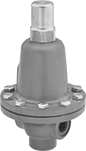 |
Commonly used as bypass lines after centrifugal, reciprocating, and rotary pumps, these valves obstruct flow to maintain sufficient operating pressure in your system. If the system pressure exceeds the set pressure, they exhaust through the threaded relief port. Adjust the set pressure within the range. Valves have a cast iron body that absorbs vibration from pressure changes to reduce wear and noise in your pipeline.
Inlet | Outlet | Relief Port | |||||||||||||||||||||||||||||||||||||||||||||||||||||||||||||||||||||||||||||||||||||||||||||||||
|---|---|---|---|---|---|---|---|---|---|---|---|---|---|---|---|---|---|---|---|---|---|---|---|---|---|---|---|---|---|---|---|---|---|---|---|---|---|---|---|---|---|---|---|---|---|---|---|---|---|---|---|---|---|---|---|---|---|---|---|---|---|---|---|---|---|---|---|---|---|---|---|---|---|---|---|---|---|---|---|---|---|---|---|---|---|---|---|---|---|---|---|---|---|---|---|---|---|---|---|
Pipe Size | Location | Max. Pressure, psi | Pipe Size | Location | Pressure Adjustment Method | Pipe Size | Location | End-to-End Lg. | For Use With | Temp. Range, ° F | Choose an Outlet Pressure, psi | Each | |||||||||||||||||||||||||||||||||||||||||||||||||||||||||||||||||||||||||||||||||||||||
NPT Female | |||||||||||||||||||||||||||||||||||||||||||||||||||||||||||||||||||||||||||||||||||||||||||||||||||
Cast Iron Body—Nickel Diaphragm and 303 Stainless Steel Seal | |||||||||||||||||||||||||||||||||||||||||||||||||||||||||||||||||||||||||||||||||||||||||||||||||||
| 1/2 | Side | 400 | 1/2 | Side | Screw | 1/2 | Bottom | 2 7/8" | Water, Oil | -40 to 200 | 0 to 25 , 5 to 50 , 30 to 100 , 75 to 175 , 150 to 400 | 4675K21 | 000000000 | ||||||||||||||||||||||||||||||||||||||||||||||||||||||||||||||||||||||||||||||||||||||
| 1 1/4 | Side | 400 | 1 1/4 | Side | Screw | 1 1/4 | Bottom | 4 1/4" | Water, Oil | -40 to 200 | 20 to 85 , 40 to 125 , 50 to 230 , 175 to 380 , 300 to 400 | 4675K25 | 00000000 | ||||||||||||||||||||||||||||||||||||||||||||||||||||||||||||||||||||||||||||||||||||||
| 1 1/2 | Side | 400 | 1 1/2 | Side | Screw | 1 1/2 | Bottom | 5" | Water, Oil | -40 to 200 | 10 to 55 , 30 to 100 , 40 to 200 , 125 to 300 , 200 to 400 | 4675K26 | 00000000 | ||||||||||||||||||||||||||||||||||||||||||||||||||||||||||||||||||||||||||||||||||||||
| 2 | Side | 400 | 2 | Side | Screw | 2 | Bottom | 5" | Water, Oil | -40 to 200 | 10 to 55 , 30 to 100 , 40 to 200 , 125 to 300 , 200 to 400 | 4675K27 | 00000000 | ||||||||||||||||||||||||||||||||||||||||||||||||||||||||||||||||||||||||||||||||||||||
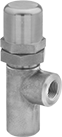
Pressure-Relief Valves for Oil
NPT Male Inlet and NPT Female Relief Port
 |
Inlet | Relief | ||||||||||||||||||||||||||||||||||||||||||||||||||||||||||||||||||||||||||||||||||||||||||||||||||
|---|---|---|---|---|---|---|---|---|---|---|---|---|---|---|---|---|---|---|---|---|---|---|---|---|---|---|---|---|---|---|---|---|---|---|---|---|---|---|---|---|---|---|---|---|---|---|---|---|---|---|---|---|---|---|---|---|---|---|---|---|---|---|---|---|---|---|---|---|---|---|---|---|---|---|---|---|---|---|---|---|---|---|---|---|---|---|---|---|---|---|---|---|---|---|---|---|---|---|---|
Pipe Size | Location | Max. Pressure, psi | Port Pipe Size | Port Location | Set Pressure Adjustment Method | Shape | Overall Ht. | For Use With | Temp. Range, ° F | Valve Type | Choose a Set Pressure, psi | Each | |||||||||||||||||||||||||||||||||||||||||||||||||||||||||||||||||||||||||||||||||||||||
Bronze Body—316 Stainless Steel Seal | |||||||||||||||||||||||||||||||||||||||||||||||||||||||||||||||||||||||||||||||||||||||||||||||||||
| 1/2 | Bottom | 1,400 | 3/4 | Side | External Adjustment Screw | 90° Elbow | 7 1/4" | Oil | -320 to 420 | Relief | 15 to 75 , 50 to 150 , 100 to 300 , 200 to 600 , 600 to 900 | 4460K81 | 0000000 | ||||||||||||||||||||||||||||||||||||||||||||||||||||||||||||||||||||||||||||||||||||||
| 3/4 | Bottom | 1,400 | 3/4 | Side | External Adjustment Screw | 90° Elbow | 7 1/4" | Oil | -320 to 420 | Relief | 15 to 75 , 50 to 150 , 100 to 300 | 4460K82 | 000000 | ||||||||||||||||||||||||||||||||||||||||||||||||||||||||||||||||||||||||||||||||||||||
| 1 | Bottom | 1,400 | 1 | Side | External Adjustment Screw | 90° Elbow | 7 1/2" | Oil | -320 to 420 | Relief | 15 to 75 , 50 to 150 , 100 to 300 , 200 to 600 , 600 to 900 | 4460K83 | 000000 | ||||||||||||||||||||||||||||||||||||||||||||||||||||||||||||||||||||||||||||||||||||||
| 1 1/4 | Bottom | 1,400 | 1 1/4 | Side | External Adjustment Screw | 90° Elbow | 8" | Oil | -320 to 420 | Relief | 15 to 75 , 50 to 150 , 100 to 300 , 200 to 600 , 600 to 900 | 4460K84 | 000000 | ||||||||||||||||||||||||||||||||||||||||||||||||||||||||||||||||||||||||||||||||||||||
| 1 1/2 | Bottom | 1,400 | 1 1/2 | Side | External Adjustment Screw | 90° Elbow | 8 7/8" | Oil | -320 to 420 | Relief | 15 to 75 , 50 to 150 , 100 to 300 , 200 to 600 | 4460K85 | 00000000 | ||||||||||||||||||||||||||||||||||||||||||||||||||||||||||||||||||||||||||||||||||||||
Pressure-Relief Valves for Cryogenic Applications
Cleaned and bagged to meet CGA G-4.1 for oxygen service and other high-purity applications, these valves are built to withstand the extreme cold of liquid carbon dioxide, liquid nitrogen, and liquid oxygen. They begin opening at the set pressure and fully open at about 10% over the set pressure. Valves begin closing as pressure drops and fully close when the system pressure is restored below the set pressure. Set pressure is not adjustable. Valves are not intended for direct contact with cryogenic liquids.
Riser Tubes—Riser tubes (sold separately) are required to convert cryogenic liquids into gases before they contact the valve. 3/8 NPT valve requires a 1/2 NPT × 3/8 NPT bushing when using a riser.
Adapters—Adapters (sold separately) convert the valve relief-port connection from UNEF female threads to NPT female threads.
Valves | Riser Tubes | Adapters | |||||||||||||||||||||||||||||||||||||||||||||||||||||||||||||||||||||||||||||||||||||||||||||||||
|---|---|---|---|---|---|---|---|---|---|---|---|---|---|---|---|---|---|---|---|---|---|---|---|---|---|---|---|---|---|---|---|---|---|---|---|---|---|---|---|---|---|---|---|---|---|---|---|---|---|---|---|---|---|---|---|---|---|---|---|---|---|---|---|---|---|---|---|---|---|---|---|---|---|---|---|---|---|---|---|---|---|---|---|---|---|---|---|---|---|---|---|---|---|---|---|---|---|---|---|
Inlet | Relief | ||||||||||||||||||||||||||||||||||||||||||||||||||||||||||||||||||||||||||||||||||||||||||||||||||
Pipe Size | Location | Max. Pressure, psi | Port Thread Size | Port Location | Overall Ht. | For Use With | Temp. Range, ° F | Choose a Set Pressure, psi | Each | Each | Each | ||||||||||||||||||||||||||||||||||||||||||||||||||||||||||||||||||||||||||||||||||||||||
NPT Male Inlet and UNEF Female Relief Port | |||||||||||||||||||||||||||||||||||||||||||||||||||||||||||||||||||||||||||||||||||||||||||||||||||
Brass Body | |||||||||||||||||||||||||||||||||||||||||||||||||||||||||||||||||||||||||||||||||||||||||||||||||||
| 1/4 | Bottom | 600 | 3/4"-20 | Top | 2 5/8" | Liquid Carbon Dioxide, Liquid Nitrogen, Liquid Oxygen | -320 to 165 | 22 , 35 , 50 , 75 , 100 , 125 , 150 , 200 , 250 , 300 , 350 , 400 , 450 | 49315K71 | 000000 | 49315K97 | 000000 | 49315K94 | 000000 | |||||||||||||||||||||||||||||||||||||||||||||||||||||||||||||||||||||||||||||||||||||
| 3/8 | Bottom | 600 | 3/4"-20 | Top | 2 5/8" | Liquid Carbon Dioxide, Liquid Nitrogen, Liquid Oxygen | -320 to 165 | 22 , 35 , 50 , 75 , 100 , 125 , 150 , 200 , 250 , 300 , 350 , 400 , 450 | 49315K72 | 00000 | 49315K98 | 00000 | 49315K94 | 00000 | |||||||||||||||||||||||||||||||||||||||||||||||||||||||||||||||||||||||||||||||||||||
| 1/2 | Bottom | 600 | 3/4"-20 | Top | 2 13/16" | Liquid Carbon Dioxide, Liquid Nitrogen, Liquid Oxygen | -320 to 165 | 22 , 35 , 50 , 75 , 100 , 125 , 150 , 200 , 250 , 300 , 350 , 400 , 450 | 49315K73 | 00000 | 49315K98 | 00000 | 49315K96 | 00000 | |||||||||||||||||||||||||||||||||||||||||||||||||||||||||||||||||||||||||||||||||||||
Tamper-Resistant Hydraulic Pressure-Relief Valves
 |
The pressure setting on these valves cannot be adjusted while they are installed. Use a hex key to unlock the locknut and turn the adjustment screw to set the pressure. Valves begin opening at the set pressure and fully open at about 10% over the set pressure. They begin closing as pressure drops and fully close when the system pressure is restored below the set pressure.
Inlet Connection | Relief Connection | Overall | |||||||||||||||||||||||||||||||||||||||||||||||||||||||||||||||||||||||||||||||||||||||||||||||||
|---|---|---|---|---|---|---|---|---|---|---|---|---|---|---|---|---|---|---|---|---|---|---|---|---|---|---|---|---|---|---|---|---|---|---|---|---|---|---|---|---|---|---|---|---|---|---|---|---|---|---|---|---|---|---|---|---|---|---|---|---|---|---|---|---|---|---|---|---|---|---|---|---|---|---|---|---|---|---|---|---|---|---|---|---|---|---|---|---|---|---|---|---|---|---|---|---|---|---|---|
Pipe Size | Dash Size | Pipe Size | Dash Size | Wd. | Ht. | For Use With | Temp. Range, ° F | Choose a Set Pressure, psi | Each | ||||||||||||||||||||||||||||||||||||||||||||||||||||||||||||||||||||||||||||||||||||||||||
NPT Female Inlet and NPT Female Relief Port | |||||||||||||||||||||||||||||||||||||||||||||||||||||||||||||||||||||||||||||||||||||||||||||||||||
Aluminum Body | |||||||||||||||||||||||||||||||||||||||||||||||||||||||||||||||||||||||||||||||||||||||||||||||||||
| 1/2 | 08 | 1/2 | 08 | 1 1/4" | 5" | Hydraulic Fluid | -40 to 250 | 40 to 125 , 115 to 250 , 235 to 450 , 630 to 850 , 630 to 1,000 , 800 to 1,500 , 1,400 to 2,100 | 5026K16 | 000000000 | |||||||||||||||||||||||||||||||||||||||||||||||||||||||||||||||||||||||||||||||||||||||||
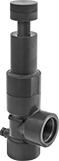
Adjustable Pressure-Relief Valves for Chemicals
NPT Female Inlet and Relief Port
 |
Inlet | Relief | Set Pressure | |||||||||||||||||||||||||||||||||||||||||||||||||||||||||||||||||||||||||||||||||||||||||||||||||
|---|---|---|---|---|---|---|---|---|---|---|---|---|---|---|---|---|---|---|---|---|---|---|---|---|---|---|---|---|---|---|---|---|---|---|---|---|---|---|---|---|---|---|---|---|---|---|---|---|---|---|---|---|---|---|---|---|---|---|---|---|---|---|---|---|---|---|---|---|---|---|---|---|---|---|---|---|---|---|---|---|---|---|---|---|---|---|---|---|---|---|---|---|---|---|---|---|---|---|---|
Pipe Size | Location | Max. Pressure, psi | Port Pipe Size | Port Location | Range, psi | Adjustment Method | Shape | Features | Overall Ht. | Gauge Port Pipe Size | For Use With | Temp. Range, ° F | Valve Type | Each | |||||||||||||||||||||||||||||||||||||||||||||||||||||||||||||||||||||||||||||||||||||
Dark Gray PVC Body—EPDM Seal | |||||||||||||||||||||||||||||||||||||||||||||||||||||||||||||||||||||||||||||||||||||||||||||||||||
| 1/2 | Bottom | 150 | 1/2 | Side | 5 to 75 | External Adjustment Screw | 90° Elbow | Gauge Port | 6 3/4" | 1/4 | Aluminum Chloride, Boric Acid | 40 to 140 | Relief | 5007K61 | 0000000 | ||||||||||||||||||||||||||||||||||||||||||||||||||||||||||||||||||||||||||||||||||||
| 3/4 | Bottom | 150 | 3/4 | Side | 5 to 75 | External Adjustment Screw | 90° Elbow | Gauge Port | 6 7/8" | 1/4 | Aluminum Chloride, Boric Acid | 40 to 140 | Relief | 5007K62 | 000000 | ||||||||||||||||||||||||||||||||||||||||||||||||||||||||||||||||||||||||||||||||||||
| 1 | Bottom | 150 | 1 | Side | 5 to 75 | External Adjustment Screw | 90° Elbow | Gauge Port | 8 3/4" | 1/4 | Aluminum Chloride, Boric Acid | 40 to 140 | Relief | 5007K63 | 000000 | ||||||||||||||||||||||||||||||||||||||||||||||||||||||||||||||||||||||||||||||||||||
| 1 1/2 | Bottom | 150 | 1 1/2 | Side | 5 to 75 | External Adjustment Screw | 90° Elbow | Gauge Port | 13 1/4" | 1/4 | Aluminum Chloride, Boric Acid | 40 to 140 | Relief | 5007K64 | 00000000 | ||||||||||||||||||||||||||||||||||||||||||||||||||||||||||||||||||||||||||||||||||||
| 2 | Bottom | 150 | 2 | Side | 5 to 75 | External Adjustment Screw | 90° Elbow | Gauge Port | 15 1/2" | 1/4 | Aluminum Chloride, Boric Acid | 40 to 140 | Relief | 5007K65 | 00000000 | ||||||||||||||||||||||||||||||||||||||||||||||||||||||||||||||||||||||||||||||||||||
Long-Life Back-Pressure-Regulating Valves for Water and Oil
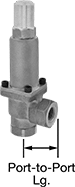 |
For a longer service than cast iron valves, these have a durable bronze body and a 303 stainless steel seal. Commonly installed as bypass lines after centrifugal, reciprocating, and rotary pumps, they obstruct flow to maintain sufficient operating pressure in your system. If the system pressure exceeds the set pressure, they exhaust through the outlet. Adjust the set pressure within the range.
Inlet | Outlet | ||||||||||||||||||||||||||||||||||||||||||||||||||||||||||||||||||||||||||||||||||||||||||||||||||
|---|---|---|---|---|---|---|---|---|---|---|---|---|---|---|---|---|---|---|---|---|---|---|---|---|---|---|---|---|---|---|---|---|---|---|---|---|---|---|---|---|---|---|---|---|---|---|---|---|---|---|---|---|---|---|---|---|---|---|---|---|---|---|---|---|---|---|---|---|---|---|---|---|---|---|---|---|---|---|---|---|---|---|---|---|---|---|---|---|---|---|---|---|---|---|---|---|---|---|---|
Pipe Size | Location | Max. Pressure, psi | Pipe Size | Location | Pressure Adjustment Method | Port-to-Port Lg. | For Use With | Temp. Range, ° F | Choose an Outlet Pressure, psi | Each | |||||||||||||||||||||||||||||||||||||||||||||||||||||||||||||||||||||||||||||||||||||||||
NPT Female | |||||||||||||||||||||||||||||||||||||||||||||||||||||||||||||||||||||||||||||||||||||||||||||||||||
Bronze Body—303 Stainless Steel Seal | |||||||||||||||||||||||||||||||||||||||||||||||||||||||||||||||||||||||||||||||||||||||||||||||||||
| 1/4 | Bottom | 600 | 1/4 | Side | Screw | 1 1/4" | Water, Oil | -40 to 450 | 15 to 30 , 25 to 75 , 50 to 140 , 100 to 300 , 200 to 600 | 4662K46 | 0000000 | ||||||||||||||||||||||||||||||||||||||||||||||||||||||||||||||||||||||||||||||||||||||||
| 3/8 | Bottom | 600 | 3/8 | Side | Screw | 1 1/4" | Water, Oil | -40 to 450 | 15 to 30 , 25 to 75 , 50 to 140 , 100 to 300 , 200 to 600 | 4662K48 | 000000 | ||||||||||||||||||||||||||||||||||||||||||||||||||||||||||||||||||||||||||||||||||||||||
| 1/2 | Bottom | 600 | 1/2 | Side | Screw | 1 5/8" | Water, Oil | -40 to 450 | 15 to 75 , 50 to 150 , 100 to 300 , 200 to 600 | 4662K32 | 000000 | ||||||||||||||||||||||||||||||||||||||||||||||||||||||||||||||||||||||||||||||||||||||||
| 3/4 | Bottom | 600 | 3/4 | Side | Screw | 1 5/8" | Water, Oil | -40 to 450 | 15 to 75 , 50 to 150 , 100 to 300 , 200 to 600 | 4662K34 | 000000 | ||||||||||||||||||||||||||||||||||||||||||||||||||||||||||||||||||||||||||||||||||||||||
| 1 | Bottom | 600 | 1 | Side | Screw | 2 1/4" | Water, Oil | -40 to 450 | 15 to 75 , 50 to 150 , 100 to 300 , 200 to 600 | 4662K36 | 000000 | ||||||||||||||||||||||||||||||||||||||||||||||||||||||||||||||||||||||||||||||||||||||||
| 1 1/4 | Bottom | 600 | 1 1/4 | Side | Screw | 2 1/4" | Water, Oil | -40 to 450 | 15 to 75 , 50 to 150 , 100 to 300 , 200 to 600 | 4662K38 | 000000 | ||||||||||||||||||||||||||||||||||||||||||||||||||||||||||||||||||||||||||||||||||||||||
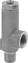
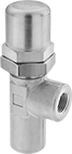
Precision-Adjustment Pressure-Relief Valves for Water
NPT Male Inlet and NPT Female Relief Port
 |
Bronze Body—Valves with a bronze body are harder and more durable than valves with a brass body for a longer service life.
Inlet | Relief | Set Pressure | |||||||||||||||||||||||||||||||||||||||||||||||||||||||||||||||||||||||||||||||||||||||||||||||||
|---|---|---|---|---|---|---|---|---|---|---|---|---|---|---|---|---|---|---|---|---|---|---|---|---|---|---|---|---|---|---|---|---|---|---|---|---|---|---|---|---|---|---|---|---|---|---|---|---|---|---|---|---|---|---|---|---|---|---|---|---|---|---|---|---|---|---|---|---|---|---|---|---|---|---|---|---|---|---|---|---|---|---|---|---|---|---|---|---|---|---|---|---|---|---|---|---|---|---|---|
Pipe Size | Location | Max. Pressure, psi | Port Pipe Size | Port Location | Range, psi | Adjustment Increment, psi | Adjustment Method | Shape | Overall Ht. | For Use With | Temp. Range, ° F | Valve Type | Each | ||||||||||||||||||||||||||||||||||||||||||||||||||||||||||||||||||||||||||||||||||||||
Brass Body—Silicone Seal | |||||||||||||||||||||||||||||||||||||||||||||||||||||||||||||||||||||||||||||||||||||||||||||||||||
| 1/2 | Bottom | 220 | 1/2 | Side | 25 to 175 | 25 | External Adjustment Screw | 90° Elbow | 4 1/8" | Water | 33 to 200 | Relief | 8088K14 | 000000 | |||||||||||||||||||||||||||||||||||||||||||||||||||||||||||||||||||||||||||||||||||||
| 3/4 | Bottom | 220 | 3/4 | Side | 25 to 175 | 25 | External Adjustment Screw | 90° Elbow | 4 1/8" | Water | 33 to 200 | Relief | 8088K16 | 00000 | |||||||||||||||||||||||||||||||||||||||||||||||||||||||||||||||||||||||||||||||||||||
Bronze Body—Silicone Seal | |||||||||||||||||||||||||||||||||||||||||||||||||||||||||||||||||||||||||||||||||||||||||||||||||||
| 1/2 | Bottom | 175 | 1/2 | Side | 50 to 175 | 25 | External Adjustment Screw | 90° Elbow | 3 7/16" | Water | 33 to 200 | Relief | 4612K16 | 00000 | |||||||||||||||||||||||||||||||||||||||||||||||||||||||||||||||||||||||||||||||||||||
| 3/4 | Bottom | 175 | 1/2 | Side | 50 to 175 | 25 | External Adjustment Screw | 90° Elbow | 3 7/16" | Water | 33 to 200 | Relief | 4612K18 | 00000 | |||||||||||||||||||||||||||||||||||||||||||||||||||||||||||||||||||||||||||||||||||||
Sanitary Back-Pressure-Regulating Valves
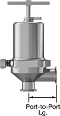 |
Designed to meet 3-A sanitary standards, these valves regulate liquid, gas, and air pressure in hygienic zones of food and beverage plants. They’re often used at the end of pipelines on processing and sanitizing equipment. Made of 316 stainless steel, they won't corrode from frequent washdowns with harsh cleaners. With an extremely smooth interior that self-drains, bacteria won't have time or space to grow. The spring and internal valve mechanisms are sealed off behind the diaphragm, which also prevents contamination. They connect with quick-clamp fittings, so disassembling to clean your line takes little time.
These valves obstruct flow to maintain sufficient operating pressure in your system. If the system pressure exceeds the set pressure, they exhaust through the outlet. They meet ANSI/FCI 70-2 Class III standards for shut-off valves, meaning a maximum of 0.1% of fluid, gas, or air will escape through the outlet when they’re closed. An integrated T-handle lets you set the outlet pressure without additional tools. The diaphragm and seal resist repeated exposure to water, and they’re FDA compliant for direct contact with food.
Inlet | Outlet | Lg. | |||||||||||||||||||||||||||||||||||||||||||||||||||||||||||||||||||||||||||||||||||||||||||||||||
|---|---|---|---|---|---|---|---|---|---|---|---|---|---|---|---|---|---|---|---|---|---|---|---|---|---|---|---|---|---|---|---|---|---|---|---|---|---|---|---|---|---|---|---|---|---|---|---|---|---|---|---|---|---|---|---|---|---|---|---|---|---|---|---|---|---|---|---|---|---|---|---|---|---|---|---|---|---|---|---|---|---|---|---|---|---|---|---|---|---|---|---|---|---|---|---|---|---|---|---|
For Tube OD | Flange OD | Location | Max. Pressure, psi | For Tube OD | Flange OD | Location | Pressure Adjustment Method | End-to-End | Port-to-Port | For Use With | Temp. Range, ° F | Specs. Met | Food Industry Std. | Choose an Outlet Pressure, psi | Each | ||||||||||||||||||||||||||||||||||||||||||||||||||||||||||||||||||||||||||||||||||||
Quick Clamp | |||||||||||||||||||||||||||||||||||||||||||||||||||||||||||||||||||||||||||||||||||||||||||||||||||
316 Stainless Steel Body—EPDM Diaphragm and Seal | |||||||||||||||||||||||||||||||||||||||||||||||||||||||||||||||||||||||||||||||||||||||||||||||||||
| 3/4" | 0.984" | Side | 200 | 3/4" | 0.984" | Bottom | T-Handle | 6 5/8" | 3 9/32" | Food, Beverage | -40 to 120 | ANSI/FCI 70-2 Class III | 3-A Certified 64-00, FDA Compliant 21 CFR 177.2600 | 5 to 30 , 35 to 90 , 50 to 105 | 4741N1 | 000000000 | |||||||||||||||||||||||||||||||||||||||||||||||||||||||||||||||||||||||||||||||||||
| 1" | 1.984" | Side | 200 | 1" | 1.984" | Bottom | T-Handle | 6 11/16" | 3 5/16" | Food, Beverage | -40 to 120 | ANSI/FCI 70-2 Class III | 3-A Certified 64-00, FDA Compliant 21 CFR 177.2600 | 5 to 30 , 35 to 90 , 50 to 105 | 4741N2 | 00000000 | |||||||||||||||||||||||||||||||||||||||||||||||||||||||||||||||||||||||||||||||||||
316 Stainless Steel Body—PTFE Diaphragm and EPDM Seal | |||||||||||||||||||||||||||||||||||||||||||||||||||||||||||||||||||||||||||||||||||||||||||||||||||
| 2" | 2.516" | Side | 100 | 2" | 2.516" | Bottom | T-Handle | 11 5/8" | 5 3/4" | Food, Beverage | -40 to 120 | ANSI/FCI 70-2 Class III | 3-A Certified 64-00, FDA Compliant 21 CFR 177.2600 | 10 to 25 , 15 to 60 | 4741N4 | 00000000 | |||||||||||||||||||||||||||||||||||||||||||||||||||||||||||||||||||||||||||||||||||
Easy-Adjust Hydraulic Pressure-Relief Valves
 |  |
Brass | 303 Stainless Steel |
An external nut lets you adjust the pressure without disassembling the valve. These valves begin opening at the set pressure and fully open at about 10% over the set pressure. They begin closing as pressure drops and fully close when the system pressure is restored below the set pressure.
Brass Body—Brass valves have good corrosion resistance.
303 Stainless Steel Body—303 stainless steel valves are more corrosion resistant than brass valves.
Inlet Connection | Relief Connection | Overall | |||||||||||||||||||||||||||||||||||||||||||||||||||||||||||||||||||||||||||||||||||||||||||||||||
|---|---|---|---|---|---|---|---|---|---|---|---|---|---|---|---|---|---|---|---|---|---|---|---|---|---|---|---|---|---|---|---|---|---|---|---|---|---|---|---|---|---|---|---|---|---|---|---|---|---|---|---|---|---|---|---|---|---|---|---|---|---|---|---|---|---|---|---|---|---|---|---|---|---|---|---|---|---|---|---|---|---|---|---|---|---|---|---|---|---|---|---|---|---|---|---|---|---|---|---|
Pipe Size | Dash Size | Pipe Size | Dash Size | Max. Flow Rate, gpm | Max. Pressure, psi | Set Pressure Adjustment Method | Lg. | Wd. | Ht. | For Use With | Temp. Range, ° F | Valve Type | Choose a Set Pressure, psi | Each | |||||||||||||||||||||||||||||||||||||||||||||||||||||||||||||||||||||||||||||||||||||
NPT Female Inlet and NPT Female Relief Port | |||||||||||||||||||||||||||||||||||||||||||||||||||||||||||||||||||||||||||||||||||||||||||||||||||
Brass Body—Buna-N Seal | |||||||||||||||||||||||||||||||||||||||||||||||||||||||||||||||||||||||||||||||||||||||||||||||||||
| 1/4 | 04 | 1/4 | 04 | 4 | 3,600 | External Adjustment Screw | 1 11/16" | 1 1/4" | 3 11/16" | Hydraulic Fluid | -40 to 250 | Relief | 4 to 15 , 10 to 50 , 40 to 125 , 115 to 250 , 235 to 450 , 430 to 650 , 630 to 850 , 630 to 1,000 , 800 to 1,500 , 1,400 to 2,100 , 1,500 to 2,750 , 2,000 to 3,100 , 3,000 to 3,600 | 4706K53 | 0000000 | ||||||||||||||||||||||||||||||||||||||||||||||||||||||||||||||||||||||||||||||||||||
| 1/2 | 08 | 1/2 | 08 | 10 | 3,600 | External Adjustment Screw | 2 3/8" | 1 3/4" | 5 7/8" | Hydraulic Fluid | -40 to 250 | Relief | 4 to 15 , 10 to 50 , 40 to 125 , 115 to 250 , 235 to 450 , 430 to 650 , 630 to 850 , 630 to 1,000 , 800 to 1,500 , 1,400 to 2,100 , 1,500 to 2,750 , 2,000 to 3,100 , 3,000 to 3,600 | 4706K57 | 000000 | ||||||||||||||||||||||||||||||||||||||||||||||||||||||||||||||||||||||||||||||||||||
| 3/4 | 12 | 3/4 | 12 | 15 | 3,600 | External Adjustment Screw | 2 7/16" | 1 3/4" | 5 15/16" | Hydraulic Fluid | -40 to 250 | Relief | 4 to 15 , 10 to 50 , 40 to 125 , 115 to 250 , 235 to 450 , 430 to 650 , 630 to 850 , 630 to 1,000 , 800 to 1,500 , 1,400 to 2,100 , 1,500 to 2,750 , 2,000 to 3,100 , 3,000 to 3,600 | 4706K59 | 000000 | ||||||||||||||||||||||||||||||||||||||||||||||||||||||||||||||||||||||||||||||||||||
303 Stainless Steel Body—Buna-N Seal | |||||||||||||||||||||||||||||||||||||||||||||||||||||||||||||||||||||||||||||||||||||||||||||||||||
| 1/2 | 08 | 1/2 | 08 | 10 | 3,600 | External Adjustment Screw | 2 3/8" | 1 3/4" | 5 7/8" | Hydraulic Fluid | -40 to 250 | Relief | 4 to 15 , 10 to 50 , 40 to 125 | 4706K67 | 00000000 | ||||||||||||||||||||||||||||||||||||||||||||||||||||||||||||||||||||||||||||||||||||
| 3/4 | 12 | 3/4 | 12 | 15 | 3,600 | External Adjustment Screw | 2 7/16" | 1 3/4" | 5 15/16" | Hydraulic Fluid | -40 to 250 | Relief | 4 to 15 , 10 to 50 , 40 to 125 | 4706K69 | 00000000 | ||||||||||||||||||||||||||||||||||||||||||||||||||||||||||||||||||||||||||||||||||||
Pressure-Regulating Inline Hydraulic Valves
 |
When input pressure varies, use these valves to maintain a consistent pressure. They are often placed after a directional-control valve and before an actuator, such as a cylinder. They have an indicator/gauge port for the inlet and one for the outlet so you can monitor that output pressure remains steady.
Inlet/Outlet Connection | Relief Connection | Overall | |||||||||||||||||||||||||||||||||||||||||||||||||||||||||||||||||||||||||||||||||||||||||||||||||
|---|---|---|---|---|---|---|---|---|---|---|---|---|---|---|---|---|---|---|---|---|---|---|---|---|---|---|---|---|---|---|---|---|---|---|---|---|---|---|---|---|---|---|---|---|---|---|---|---|---|---|---|---|---|---|---|---|---|---|---|---|---|---|---|---|---|---|---|---|---|---|---|---|---|---|---|---|---|---|---|---|---|---|---|---|---|---|---|---|---|---|---|---|---|---|---|---|---|---|---|
Pipe Size | Dash Size | Pipe Size | Dash Size | Max. Flow Rate, gpm | Max. Pressure, psi | Lg. | Wd. | Ht. | For Use With | Choose a Set Pressure, psi | Each | ||||||||||||||||||||||||||||||||||||||||||||||||||||||||||||||||||||||||||||||||||||||||
NPT Female Inlet and Relief Port | |||||||||||||||||||||||||||||||||||||||||||||||||||||||||||||||||||||||||||||||||||||||||||||||||||
Cast Iron Body—Buna-N Seal | |||||||||||||||||||||||||||||||||||||||||||||||||||||||||||||||||||||||||||||||||||||||||||||||||||
| 3/4 | 12 | 1/4 | 04 | 33 | 3,000 | 5 7/8" | 3 3/4" | 7 1/8" | Hydraulic Fluid | 100 to 1,000 , 500 to 2,000 , 1,000 to 3,000 | 9474T2 | 0000000 | |||||||||||||||||||||||||||||||||||||||||||||||||||||||||||||||||||||||||||||||||||||||
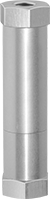
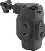
Screw-In Hydraulic Pressure-Relief Valves
Set a specific pressure and these valves will maintain it. Also known as cartridge valves, these compact valves screw into your mounting block. They begin opening at the set pressure and fully open at about 20% over the set pressure. They begin closing as pressure drops and fully close when the system pressure is restored below the set pressure.
Body—UN/UNF (SAE Straight) | Set Pressure | ||||||||||||||||||||||||||||||||||||||||||||||||||||||||||||||||||||||||||||||||||||||||||||||||||
|---|---|---|---|---|---|---|---|---|---|---|---|---|---|---|---|---|---|---|---|---|---|---|---|---|---|---|---|---|---|---|---|---|---|---|---|---|---|---|---|---|---|---|---|---|---|---|---|---|---|---|---|---|---|---|---|---|---|---|---|---|---|---|---|---|---|---|---|---|---|---|---|---|---|---|---|---|---|---|---|---|---|---|---|---|---|---|---|---|---|---|---|---|---|---|---|---|---|---|---|
Deltrol Equivalent Model No. | Hydraforce Equivalent Model No. | Thread Size | Dash Size | Max. Flow Rate, gpm | Max. Pressure, psi | Range, psi | Adjustment Method | Overall Ht. | For Use With | Valve Type | Each | ||||||||||||||||||||||||||||||||||||||||||||||||||||||||||||||||||||||||||||||||||||||||
Inlet Relief Port | |||||||||||||||||||||||||||||||||||||||||||||||||||||||||||||||||||||||||||||||||||||||||||||||||||
Anodized Aluminum Body—Buna-N Seal | |||||||||||||||||||||||||||||||||||||||||||||||||||||||||||||||||||||||||||||||||||||||||||||||||||
| DRV2-080-N-K-4 | — | 3/4"-16 | 08 | 10 | 3,000 | 100 to 400 | Knob | 4" | Hydraulic Fluid | Relief | 1628N11 | 000000 | |||||||||||||||||||||||||||||||||||||||||||||||||||||||||||||||||||||||||||||||||||||||
| DRV2-080-N-K-20 | — | 3/4"-16 | 08 | 10 | 3,000 | 300 to 2,000 | Knob | 4" | Hydraulic Fluid | Relief | 1628N12 | 00000 | |||||||||||||||||||||||||||||||||||||||||||||||||||||||||||||||||||||||||||||||||||||||
| DRV2-080-N-K-30 | — | 3/4"-16 | 08 | 10 | 3,000 | 1,500 to 3,000 | Knob | 4" | Hydraulic Fluid | Relief | 1628N13 | 00000 | |||||||||||||||||||||||||||||||||||||||||||||||||||||||||||||||||||||||||||||||||||||||
| DRV-100-N-K-4 | RV10-20A-0-N | 7/8"-14 | 10 | 10 | 3,000 | 100 to 400 | Knob | 4 1/2" | Hydraulic Fluid | Relief | 1628N14 | 00000 | |||||||||||||||||||||||||||||||||||||||||||||||||||||||||||||||||||||||||||||||||||||||
| DRV-100-N-K-20 | RV10-20A-0-N | 7/8"-14 | 10 | 10 | 3,000 | 300 to 2,000 | Knob | 4 1/2" | Hydraulic Fluid | Relief | 1628N15 | 00000 | |||||||||||||||||||||||||||||||||||||||||||||||||||||||||||||||||||||||||||||||||||||||
| DRV-100-N-K-30 | RV10-20A-0-N | 7/8"-14 | 10 | 10 | 3,000 | 1,500 to 3,000 | Knob | 4 1/2" | Hydraulic Fluid | Relief | 1628N16 | 00000 | |||||||||||||||||||||||||||||||||||||||||||||||||||||||||||||||||||||||||||||||||||||||
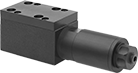
Block-Mount Hydraulic Pressure-Relief Valves
 | 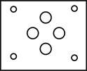 |
D03 Mounting Pattern |
Set a specific pressure and this valve will maintain it by diverting excess fluid from a pump to a tank. Valve opens at set pressure and closes when pressure drops. Use screws to attach to an NFPA valve-mounting block (each component sold separately).
Valves | Screws | ||||||||||||||||||||||||||||||||||||||||||||||||||||||||||||||||||||||||||||||||||||||||||||||||||
|---|---|---|---|---|---|---|---|---|---|---|---|---|---|---|---|---|---|---|---|---|---|---|---|---|---|---|---|---|---|---|---|---|---|---|---|---|---|---|---|---|---|---|---|---|---|---|---|---|---|---|---|---|---|---|---|---|---|---|---|---|---|---|---|---|---|---|---|---|---|---|---|---|---|---|---|---|---|---|---|---|---|---|---|---|---|---|---|---|---|---|---|---|---|---|---|---|---|---|---|
Set Pressure | Overall | ||||||||||||||||||||||||||||||||||||||||||||||||||||||||||||||||||||||||||||||||||||||||||||||||||
NFPA Mounting Pattern | ISO Mounting Pattern | Max. Flow Rate, gpm | Max. Pressure, psi | Range, psi | Adjustment Method | Lg. | Wd. | Ht. | For Use With | Valve Type | Each | Pkg. Qty. | Pkg. | ||||||||||||||||||||||||||||||||||||||||||||||||||||||||||||||||||||||||||||||||||||||
Inlet Relief Port | |||||||||||||||||||||||||||||||||||||||||||||||||||||||||||||||||||||||||||||||||||||||||||||||||||
Fluoroelastomer Seal | |||||||||||||||||||||||||||||||||||||||||||||||||||||||||||||||||||||||||||||||||||||||||||||||||||
| D03 | 03 | 6.5 | 5,000 | 265 to 3,000 | External Adjustment Screw | 6 5/8" | 1 7/8" | 2" | Hydraulic Fluid | Relief | 1624N11 | 000000000 | 4 | 1945N14 | 00000 | ||||||||||||||||||||||||||||||||||||||||||||||||||||||||||||||||||||||||||||||||||||
Pressure-Regulating Block-Mount Hydraulic Valves
| |
D03 Mounting Pattern |
These valves maintain a consistent pressure in a system when input pressure varies. They are often placed after a directional-control valve and before an actuator, such as a cylinder. Use screws to attach to an NFPA valve-mounting block (each component sold separately).
