


Choosing an Electrical Switch
More
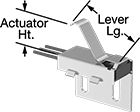
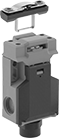
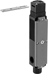
Heavy Duty Limit Switches

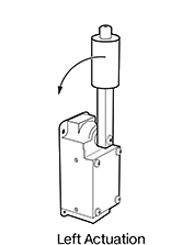
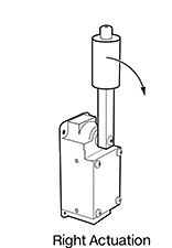
Rugged enough for mining operations, these limit switches require a high actuation force, like heavy rocks moving on a conveyor. They open and close a circuit as quickly as a snap-acting switch but have a larger actuator for larger objects. The roller on the end of the lever arm reduces friction to prevent wear and tear on the switch. Rated NEMA 4 and 13 as well as IP67, these switches are protected from dirt, oil spraying, and temporary submersion.
To determine if you need a right or left actuation direction, stand facing where you'll put the switch. If objects will be passing to the right, you'll need a right actuation direction. If they'll be passing to the left, you'll need a left actuation direction.
Housing | |||||||||||||||
|---|---|---|---|---|---|---|---|---|---|---|---|---|---|---|---|
| Actuation Direction | No. of Circuits Controlled | Switch Starting Position | Switch Action | Industry Designation | Switching Current @ Voltage | Max. Voltage | Actuation Force | Operating Temp. Range, °F | Actuator Ht. | For Max. Cable OD | Lg. | Ht. | Dp. | Each | |
Aluminum Housing with Screw Terminals | |||||||||||||||
| Left | 2 | 2 Off (Normally Open) | Springs Back (Momentary) | DPST-NO | 20 A @ 120 V AC, 5 A @ 120 V DC | 600V AC 600V DC | 150 in.-oz. | -10° to 185° | 5.7" | 1/2" | 2.3" | 5" | 3.4" | 0000000 | 0000000 |
| Left | 2 | 2 On (Normally Closed) | Springs Back (Momentary) | DPST-NC | 20 A @ 120 V AC, 5 A @ 120 V DC | 600V AC 600V DC | 150 in.-oz. | -10° to 185° | 5.7" | 1/2" | 2.3" | 5" | 3.4" | 0000000 | 000000 |
| Right | 2 | 2 Off (Normally Open) | Springs Back (Momentary) | DPST-NO | 20 A @ 120 V AC, 5 A @ 120 V DC | 600V AC 600V DC | 150 in.-oz. | -10° to 185° | 5.7" | 1/2" | 2.3" | 5" | 2" | 0000000 | 000000 |
| Right | 2 | 2 On (Normally Closed) | Springs Back (Momentary) | DPST-NC | 20 A @ 120 V AC, 5 A @ 120 V DC | 600V AC 600V DC | 150 in.-oz. | -10° to 185° | 5.7" | 1/2" | 2.3" | 5" | 2" | 0000000 | 000000 |
| Right | 2 | 1 Off (Normally Open) and 1 On (Normally Closed) | Springs Back (Momentary) | DPST-1NO/1NC | 20 A @ 120 V AC, 5 A @ 120 V DC | 600V AC 600V DC | 150 in.-oz. | -10° to 185° | 5.7" | 1/2" | 2.3" | 5" | 2" | 0000000 | 000000 |
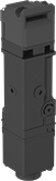
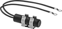
Harsh Environment Snap-Acting Switches
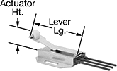
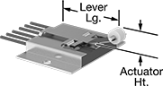
Open and close circuits in a snap—even in harsh conditions. With a rubber-encased housing and stainless steel bracket, these switches handle high vibrations and resist corrosion. They’re rated IP68 for protection from dust and temporary submersion. Because they open and close circuits faster than other switches—reducing the time that contacts are near one another—they prevent contacts from sticking. They also minimize the chance of arcing, so electricity won’t jump across contacts. They’re often used as door-open indicators on enclosures or as an internal component in limit, pressure, and temperature switches.
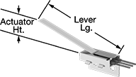
Lever actuator switches can be pushed down by front-to-back movement, so they can be activated with pressure anywhere along their length.
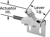
Roller lever actuator switches activate when parts glide front-to-back across their actuation surface. They produce less friction than standard levers, which prevents wear and tear over time.
Simulated roller lever actuator switches have a curved arm that can be pressed down for actuation by forward, backward, and repeated back-and-forth movement.
Dual switch roller lever actuator switches actuate two SPDT switches simultaneously, giving you the equivalent of a DPDT switch. A roller at the end of the arm reduces friction and wear from parts moving across their actuation surface.
Wire Leads | Housing | ||||||||||||||||
|---|---|---|---|---|---|---|---|---|---|---|---|---|---|---|---|---|---|
| No. of Circuits Controlled | Switch Starting Position | Switch Action | Industry Designation | Switching Current @ Voltage | Max. Voltage | Operating Temp. Range, °F | Actuator Ht. | Wire Connection Type | No. of | Lg. | Lg. | Ht. | Dp. | Lever Lg. | Each | ||
Side Mount | |||||||||||||||||
Lever Actuator Style | |||||||||||||||||
| A | 1 | 1 Off (Normally Open) | Springs Back (Momentary) | SPST-NO | 5 A @ 120 V AC, 5 A @ 28 V DC | 120V AC 28V DC | -40° to 185° | 1.04" | Wire Leads | 2 | 24" | 0.86" | 1.13" | 1.75" | 4.5" | 00000000 | 0000000 |
| A | 1 | 1 Off (Normally Open) or 1 On (Normally Closed) | Springs Back (Momentary) | SPDT | 5 A @ 120 V AC, 5 A @ 28 V DC | 120V AC 28V DC | -40° to 185° | 1.04" | Wire Leads | 3 | 24" | 0.86" | 1.13" | 1.75" | 4.5" | 0000000 | 00000 |
Roller Lever Actuator Style | |||||||||||||||||
| B | 1 | 1 Off (Normally Open) | Springs Back (Momentary) | SPST-NO | 5 A @ 120 V AC, 5 A @ 28 V DC | 120V AC 28V DC | -40° to 185° | 0.81" | Wire Leads | 2 | 24" | 1" | 1.42" | 1.75" | 1.4" | 00000000 | 000000 |
| B | 1 | 1 Off (Normally Open) or 1 On (Normally Closed) | Springs Back (Momentary) | SPDT | 5 A @ 120 V AC, 5 A @ 28 V DC | 120V AC 28V DC | -40° to 185° | 0.81" | Wire Leads | 3 | 24" | 1" | 1.42" | 1.75" | 1.4" | 0000000 | 00000 |
Simulated Roller Lever Actuator Style | |||||||||||||||||
| C | 1 | 1 Off (Normally Open) | Springs Back (Momentary) | SPST-NO | 5 A @ 120 V AC, 5 A @ 28 V DC | 120V AC 28V DC | -40° to 185° | 0.81" | Wire Leads | 2 | 24" | 1" | 1.42" | 1.75" | 1.3" | 00000000 | 000000 |
| C | 1 | 1 Off (Normally Open) or 1 On (Normally Closed) | Springs Back (Momentary) | SPDT | 5 A @ 120 V AC, 5 A @ 28 V DC | 120V AC 28V DC | -40° to 185° | 0.81" | Wire Leads | 3 | 24" | 1" | 1.42" | 1.75" | 1.3" | 0000000 | 00000 |
Bottom Mount | |||||||||||||||||
Roller Lever Actuator Style | |||||||||||||||||
| D | 1 | 1 Off (Normally Open) | Springs Back (Momentary) | SPST-NO | 5 A @ 120 V AC, 5 A @ 28 V DC | 120V AC 28V DC | -40° to 185° | 0.61" | Wire Leads | 2 | 24" | 1.75" | 0.34" | 1.75" | 2.2" | 00000000 | 000000 |
| D | 1 | 1 Off (Normally Open) or 1 On (Normally Closed) | Springs Back (Momentary) | SPDT | 5 A @ 120 V AC, 5 A @ 28 V DC | 120V AC 28V DC | -40° to 185° | 0.61" | Wire Leads | 3 | 24" | 1.75" | 0.34" | 1.75" | 2.2" | 0000000 | 00000 |
Dual Switch Roller Lever Actuator Style | |||||||||||||||||
| E | 2 | 1 Off (Normally Open) or 1 On (Normally Closed) | Springs Back (Momentary) | SPDT | 5 A @ 120 V AC, 5 A @ 28 V DC | 120V AC 28V DC | -40° to 185° | 0.6" | Wire Leads | 6 | 24" | 2.5" | 1.25" | 1.75" | 2.3" | 0000000 | 000000 |
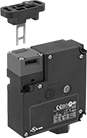
Frame-Mounted Safety Switches
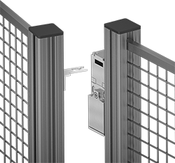
Also known as interlock switches, these ensure the safety of personnel by automatically shutting off power to machinery when an access door opens. Mount the switch to the door frame and mount a key to the door so that the key is inserted into the switch when the door is closed. When the door opens, the key is removed from the switch and the machine shuts down. They’re often used with machine guards for large robots.
All switches require an actuator key, but not all include one—check whether you need to pick out a separate actuator key. For some switch styles, you can also select the mounting orientation of the key. Flexible keys pivot at least 15°, making them easier to align with switches during installation.
Style A-G switches have positive-force, normally closed contacts that will open a circuit when the switch is actuated even if a spring fails or the contacts stick.
IP67 rated switches protect against temporary submersion. NEMA 4 rated switches protect against washdowns. NEMA 6 rated switches protect against both temporary submersion and washdowns.
Housing | Conduit | ||||||||||||||||
|---|---|---|---|---|---|---|---|---|---|---|---|---|---|---|---|---|---|
| Style | No. of Circuits Controlled | Switch Starting Position | Switch Action | No. of Terminals | Industry Designation | Switching Current @ Voltage | Max. Voltage | Ht. | Wd. | Dp. | Trade Size | Thread Size | Thread Type | Key Included | Environmental Rating | Each | |
Wire Lead Connection with Positive-Force Normally Closed Contacts | |||||||||||||||||
| A | 2 | 1 Off (Normally Open) and 1 On (Normally Closed) | Stays Switched (Maintained) | 2 | DPST-1NO/1NC | 8 A @ 120 V AC, 4 A @ 24 V DC | 250V AC 24V DC | 3.3" | 1.2" | 1.2" | __ | M16 | Metric | Yes | IP67 | 00000000 | 0000000 |
Screw Terminal Connection with Positive-Force Normally Closed Contacts | |||||||||||||||||
| B | 2 | 1 Off (Normally Open) and 1 On (Normally Closed) | Stays Switched (Maintained) | 4 | DPST-1NO/1NC | 5 A @ 120 V AC, 2 A @ 24 V DC | 500V AC 250V DC | 3" | 1" | 1.1" | 1/2 | __ | NPT | Yes | IP67, NEMA 6 | 00000000 | 000000 |
| C | 2 | 1 Off (Normally Open) and 1 On (Normally Closed) | Stays Switched (Maintained) | 4 | DPST-1NO/1NC | 10 A @ 120 V AC, 2 A @ 24 V DC | 250V AC 24V DC | 3.6" | 2.1" | 1.3" | 1/2 | __ | NPT | Yes | IP65, NEMA 4 | 00000000 | 000000 |
| C | 3 | 1 Off (Normally Open) and 2 On (Normally Closed) | Stays Switched (Maintained) | 3 | 3PST-1NO/2NC | 8 A @ 120 V AC, 4 A @ 24 V DC | 600V AC 250V DC | 3.5" | 2.1" | 1.2" | 1/2 | __ | NPT | Yes | IP67 | 00000000 | 000000 |
| D | 3 | 1 Off (Normally Open) and 2 On (Normally Closed) | Stays Switched (Maintained) | 6 | 3PST-1NO/2NC | 6 A @ 120 V AC, 0.27 A @ 24 V DC | 240V AC 250V DC | 3.8" | 1.2" | 1.2" | 1/2 | __ | NPT | Yes | IP67 | 00000000 | 00000 |
Screw Terminal Connection with Positive-Force Normally Closed Contacts and Rotating Head | |||||||||||||||||
| C | 3 | 1 Off (Normally Open) and 2 On (Normally Closed) | Stays Switched (Maintained) | 6 | 3PST-1NO/2NC | 5 A @ 120 V AC, 5 A @ 24 V DC | 400V AC 400V DC | 3.5" | 2" | 1.3" | 1/2 | __ | NPT | Yes | IP65 | 00000000 | 000000 |
| D | 3 | 1 Off (Normally Open) and 2 On (Normally Closed) | Stays Switched (Maintained) | 6 | 3PST-1NO/2NC | 10 A @ 120 V AC, 2.5 A @ 125 V DC | 240V AC 250V DC | 3.8" | 1.2" | 1.2" | __ | M20 | Metric | No | IP67 | 00000000 | 00000 |
Screw Terminal Connection with Rotating Head | |||||||||||||||||
| H | 4 | 2 Off (Normally Open) and 2 On (Normally Closed) | Stays Switched (Maintained) | 8 | 4PST-2NO/2NC | 2.5 A @ 120 V AC, 1 A @ 125 V DC | 120V AC 125V DC | 7.1" | 1.5" | 1.5" | 1/2 | __ | NPT | No | IP67 | 00000000 | 000000 |


Access-Delay Frame-Mounted Safety Switches
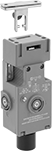
Delay access to hazardous areas until conditions are safe; use these switches with machines that take time to stop after they are turned off. Mount the switch to the door frame and mount the key to the door so that the key is inserted into the switch when the door is closed. When the door is pulled, the key is held in place with 225 lbs. of force until the switch receives a signal from a time-delay relay, motion sensor, or position sensor (not included) that the machine’s motion has stopped. After the motion has stopped, the key can be removed from the switch, releasing the access door. They’re often used with machine guards. All have positive-force, normally-closed contacts that will open a circuit when the switch is actuated even if a spring fails or the contacts stick. They’re rated for protection from washdowns and temporary submersion.
Style A and B have a key entry on the top and side of the switch.
Style C has a key entry on two opposite sides of the switch.
Emergency override keys (sold separately) bypass the access delay feature.
Housing | ||||||||||||||||
|---|---|---|---|---|---|---|---|---|---|---|---|---|---|---|---|---|
| Style | No. of Circuits Controlled | Switch Starting Position | Switch Action | No. of Terminals | Industry Designation | Switching Current @ Voltage | Max. Voltage | Input Voltage | Holding Force, lbs. | Ht. | Wd. | Dp. | Wire Connection Type | Conduit Trade Size | Each | |
Positive-Force Normally Closed Contacts | ||||||||||||||||
| A | 3 | 1 Off (Normally Open) and 2 On (Normally Closed) | Stays Switched (Maintained) | 6 | 3PST-1NO/2NC | 5 A @ 120 V AC, 2 A @ 24 V DC | 500V AC 250V DC | 24V AC, 24V DC | 225 | 4.7" | 2.3" | 1.4" | Screw Terminals | 1/2 | 0000000 | 0000000 |
| A | 3 | 1 Off (Normally Open) and 2 On (Normally Closed) | Stays Switched (Maintained) | 6 | 3PST-1NO/2NC | 5 A @ 120 V AC, 2 A @ 24 V DC | 500V AC 250V DC | 110V AC | 225 | 4.7" | 2.3" | 1.4" | Screw Terminals | 1/2 | 0000000 | 000000 |
| B | 3 | 1 Off (Normally Open) and 2 On (Normally Closed) | Stays Switched (Maintained) | 14 | 3PST-1NO/2NC | 3 A @ 120 V AC, 2.5 A @ 24 V DC | 250V DC 240V AC | 24V DC | 225 | 3.7" | 3.5" | 1.4" | Screw Terminals | 1/2 | 0000000 | 000000 |
Positive-Force Normally Closed Contacts and Rotating Head | ||||||||||||||||
| C | 4 | 2 Off (Normally Open) and 2 On (Normally Closed) | Stays Switched (Maintained) | 8 | 4PST-2NO/2NC | 4 A @ 120 V AC, 4 A @ 24 V DC | 240V AC 24V DC | 24V AC, 24V DC | 225 | 7.6" | 1.2" | 1.6" | Screw Terminals | 1/2 | 0000000 | 000000 |
| Emergency Override Key for Style A | 0000000 | Each | 000000 |
Tilt Switches
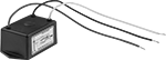
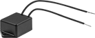
Often used as position indicators, pump level controls, and machine limit switches, these switches actuate when tilted to a certain angle. They mount horizontally and activate when tilted downward, and deactivate when tilted up. Differential angle is the total angle from the point of activation to the point of deactivation. All combine electromechanical and solid state technologies for reliability and long life.
| No. of Circuits Controlled | Switch Starting Position | Industry Designation | Switching Current @ Voltage | Max. Voltage | Differential Angle | No. of Wire Leads | Dia. | Lg. | Ht. | Dp. | Housing Material | Environmental Rating | Each | ||
With Ring Terminals | |||||||||||||||
|---|---|---|---|---|---|---|---|---|---|---|---|---|---|---|---|
| A | 1 | 1 Off (Normally Open) | SPST-NO | 0.1 A @ 120 V AC, 0.25 A @ 24 V DC | 60V DC/120V AC | 15° | 2 | 0.53" | 1.88" | __ | __ | Plastic | NEMA 4, IP67 | 000000 | 000000 |
With Spade Terminals | |||||||||||||||
| A | 1 | 1 Off (Normally Open) | SPST-NO | 2.5 A @ 120 V AC | 280V AC | 15° | 2 | 0.53" | 1.88" | __ | __ | Plastic | NEMA 4, IP67 | 000000 | 00000 |
With Wire Leads | |||||||||||||||
| D | 1 | 1 Off (Normally Open) | SPST-NO | 15 A @ 120 V AC | 120V AC | 15° | 3 | __ | 3" | 1.5" | 2" | Plastic | NEMA 4, IP67 | 000000 | 000000 |
| E | 1 | 1 On (Normally Closed) | SPST-NC | 2 A @ 120 V AC | 220V AC | 25° | 2 | __ | 1.5" | 0.8" | 1.3" | Plastic | NEMA 4, IP67 | 000000 | 00000 |
| E | 1 | 1 On (Normally Closed) | SPST-NC | 2 A @ 120 V AC | 220V AC | 40° | 2 | __ | 1.5" | 0.8" | 1.3" | Plastic | NEMA 4, IP67 | 000000 | 00000 |
Air-Actuated Foot Switches
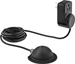
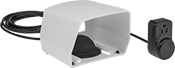
Press these switches with your foot for convenient, hands-free operation. They use air pressure to turn circuits on or off, keeping live electrical circuits away from work areas. Use the three-prong outlet to plug a device directly into the switch.
| No. of Circuits Controlled | Switch Starting Position | Switch Action | No. of Terminals | Industry Designation | Switching Current @ Voltage | Dia. | Lg. | Wd. | Ht. | Guard Material | Includes | Each | |
With Three-Prong Outlet | |||||||||||||
|---|---|---|---|---|---|---|---|---|---|---|---|---|---|
| 1 | 1 Off (Normally Open) | Springs Back (Momentary) | 2 | SPST-NO | 15 A @ 120 V AC | 3 3/4" | __ | __ | 1 1/2" | __ | 10 ft. Tubing | 0000000 | 000000 |
| 1 | 1 Off (Normally Open) | Stays Switched (Maintained) | 2 | SPST-NO | 15 A @ 120 V AC | 3 3/4" | __ | __ | 1 1/2" | __ | 10 ft. Tubing | 0000000 | 00000 |
With Three-Prong Outlet and Guard | |||||||||||||
| 1 | 1 Off (Normally Open) | Springs Back (Momentary) | 2 | SPST-NO | 15 A @ 120 V AC | __ | 6" | 6 1/2" | 4 11/16" | Plastic | 10 ft. Tubing | 0000000 | 00000 |
| 1 | 1 Off (Normally Open) | Stays Switched (Maintained) | 2 | SPST-NO | 15 A @ 120 V AC | __ | 6" | 6 1/2" | 4 11/16" | Plastic | 10 ft. Tubing | 0000000 | 00000 |
Speed-Monitoring Switches
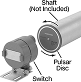

Detect unwanted slowdowns in a rotary shaft that could cause machine damage and downtime. These switches are often used on drivetrains, conveyors, and other power-driven components. They come with a pulser disc, which you’ll need to attach to the shaft by drilling and tapping a hole. Once mounted, the disc rotates with the shaft and creates magnetic signals that the switch senses. When the speed falls below a set point, the switch will trigger an alarm or turn off the system.
Switches are UL listed and rated NEC Class I, Divisions 1 and 2, Groups C and D; and Class II, Divisions 1 and 2, Groups E, F, and G. They have an explosion-proof housing and are also rated NEMA 4X for washdown and corrosion protection.
Switching | Input | Conduit | Mounting Slot | ||||||||||||
|---|---|---|---|---|---|---|---|---|---|---|---|---|---|---|---|
| Activation Point Range, rpm | Current, A | Voltage | Voltage | Frequency, Hz | No. of Terminals | Trade Size | Thread Type | Gender | Lg. | Wd. | No. of | Mounting Fasteners Included | Environmental Rating | Each | |
1 Off (Normally Open), 1 On (Normally Closed) Starting Switch Position | |||||||||||||||
SPDT | |||||||||||||||
| 5-100 | 5 | 120V AC | 120V AC | 60 | 5 | 1 | NPT | Female | 1 1/4" | 0.32" | 2 | Yes | NEC Class I Divisions 1, 2 Groups C, D NEC Class II Divisions 1, 2 Groups E, F, G NEMA 4X | 0000000 | 0000000 |