


Choosing a Proximity Switch
More
Choosing an Electrical Switch
More
Heavy Duty Limit Switches

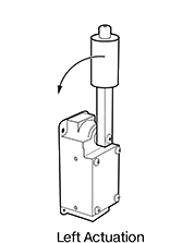
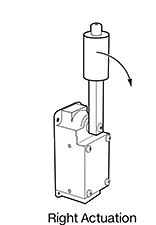
Rugged enough for mining operations, these limit switches require a high actuation force, like heavy rocks moving on a conveyor. They open and close a circuit as quickly as a snap-acting switch but have a larger actuator for larger objects. The roller on the end of the lever arm reduces friction to prevent wear and tear on the switch. Rated NEMA 4 and 13 as well as IP67, these switches are protected from dirt, oil spraying, and temporary submersion.
To determine if you need a right or left actuation direction, stand facing where you'll put the switch. If objects will be passing to the right, you'll need a right actuation direction. If they'll be passing to the left, you'll need a left actuation direction.
![]() For technical drawings and 3-D models, click on a part number.
For technical drawings and 3-D models, click on a part number.
Housing | |||||||||||||||
|---|---|---|---|---|---|---|---|---|---|---|---|---|---|---|---|
| Actuation Direction | No. of Circuits Controlled | Switch Starting Position | Switch Action | Industry Designation | Switching Current @ Voltage | Max. Voltage | Actuation Force | Operating Temp. Range, °F | Actuator Ht. | For Max. Cable OD | Lg. | Ht. | Dp. | Each | |
Aluminum Housing with Screw Terminals | |||||||||||||||
| Left | 2 | 2 Off (Normally Open) | Springs Back (Momentary) | DPST-NO | 20 A @ 120 V AC, 5 A @ 120 V DC | 600V AC 600V DC | 150 in.-oz. | -10° to 185° | 5.7" | 1/2" | 2.3" | 5" | 3.4" | 0000000 | 0000000 |
| Right | 2 | 2 Off (Normally Open) | Springs Back (Momentary) | DPST-NO | 20 A @ 120 V AC, 5 A @ 120 V DC | 600V AC 600V DC | 150 in.-oz. | -10° to 185° | 5.7" | 1/2" | 2.3" | 5" | 2" | 0000000 | 000000 |
Valve Position Switches

These switches sense when a valve is open or closed, supporting flow and temperature control within your system. Secure the switch to your valve actuator’s mounting holes, and attach an activator (sold separately) to the actuator's shaft. As the actuator opens and closes the valve, the activator rotates until its targets align with the switch’s two inductive sensors. Once they’re aligned, your system will know that the valve is either open or closed—offering reliable feedback on your valve’s position. Connect these switches to programmable logic controllers (PLCs) to support automated processes. They meet various national and international safety standards, and they’re rated IP67 to protect against dust, washdowns, and temporary submersion.
![]() For technical drawings and 3-D models, click on a part number.
For technical drawings and 3-D models, click on a part number.


Micro
M12 Plug
Switches with curved face minimize pinch points between the switch and activator, making them good for manually-controlled valves.
Switches with a 4-pole micro M12 plug connect to cables with a socket (sold separately), letting you quickly connect and disconnect the switch from your equipment.
To view switch wiring diagrams, select a part number and click Product Detail.
| Switch Starting Position | Switching Frequency, Hz | Max. Sensing Distance, mm | Signal Output Type | Input Voltage | Current Output | No. of Wire Leads | Lg., mm | Circuit Protection | Cable Lead Lg., ft. | Temperature Range, °F | Environmental Rating | Each | |
With Flat Face | |||||||||||||
|---|---|---|---|---|---|---|---|---|---|---|---|---|---|
With 4-Pole Micro M12 Plug | |||||||||||||
| 2 Off (Normally Open) | 500 | 3 | PNP | 10V DC-30V DC | 100mA | __ | 36 | Reverse Polarity | __ | -10° to 155° | IP67 | 0000000 | 0000000 |
With Wire Leads | |||||||||||||
| 2 Off (Normally Open) | 500 | 3 | PNP | 10V DC-30V DC | 100mA | 4 | 36 | Reverse Polarity | 16 | -10° to 155° | IP67 | 0000000 | 000000 |
With Spring-Clamp Terminals | |||||||||||||
| 2 Off (Normally Open) | 500 | 3 | PNP | 10V DC-30V DC | 100mA | __ | 78 | Reverse Polarity | __ | -10° to 155° | IP67 | 0000000 | 000000 |
With Curved Face | |||||||||||||
With 4-Pole Micro M12 Plug | |||||||||||||
| 2 Off (Normally Open) | 500 | 3 | PNP | 10V DC-30V DC | 200mA | __ | 35 | Reverse Polarity | __ | -10° to 155° | IP67 | 0000000 | 000000 |
| 2 Off (Normally Open) | 1,000 | 4 | PNP | 10V DC-30V DC | 200mA | __ | 42 | Reverse Polarity | __ | -10° to 155° | IP67 | 0000000 | 000000 |
With Wire Leads | |||||||||||||
| 2 Off (Normally Open) | 500 | 3 | PNP | 10V DC-30V DC | 200mA | 4 | 42 | Reverse Polarity | 16 | -10° to 155° | IP67 | 0000000 | 000000 |
| 2 Off (Normally Open) | 1,000 | 4 | PNP | 10V DC-30V DC | 200mA | 4 | 42 | Reverse Polarity | 6 1/2 | -10° to 155° | IP67 | 0000000 | 000000 |
With Screw Terminals | |||||||||||||
| 2 Off (Normally Open) | 1,000 | 4 | PNP | 10V DC-30V DC | 200mA | __ | 64 | Reverse Polarity | __ | -10° to 155° | IP67 | 0000000 | 000000 |


The position of metal targets on your activator determines when your switch sends a signal to your PLC. To install, line up one of the activator's targets with one of the switch's sensors while your valve is closed. Choose an activator that prompts your desired signal.
Styles A and F prompt a signal from your sensor to your system when your valve is fully opened and closed.
Style B have a symmetrical design so you can position a switch on both sides of the activator to create redundant signals and support safety applications.
Style C prompt a signal from your sensor when your valve is not fully opened or closed—such as when your valve is in motion or stuck partially open.
Style D have customizable targets, prompting a signal when your valve reaches the position or range of motion you select.
Style E include a housing that protects the activator against debris and damage. Colored on/off indicators make readings clear from far away. Use the included captive screws for easy mounting.
Housing | ||||||||||||||
|---|---|---|---|---|---|---|---|---|---|---|---|---|---|---|
| Style | For Maximum Shaft Dia., mm | For Minimum Shaft Dia., mm | For Shaft Lg., mm | Indicator Color | Dia., mm | Ht., mm | Body Material | Temperature Range, °F | Mounting Fasteners Included | Dia., mm | Ht., mm | Material | Each | |
For Switches with Flat Face | ||||||||||||||
| A | 58 | __ | 20, 30 | __ | 65 | 39 | Plastic | -10° to 155° | Yes | __ | __ | __ | 0000000 | 000000 |
| A | 90 | __ | 20, 50 | __ | 115 | 63 | Plastic | -10° to 155° | Yes | __ | __ | __ | 0000000 | 00000 |
| B | 58 | __ | 20, 30 | __ | 65 | 39 | Plastic | -10° to 155° | Yes | __ | __ | __ | 0000000 | 00000 |
| C | 58 | __ | 20, 30 | __ | 65 | 39 | Plastic | -10° to 155° | Yes | __ | __ | __ | 0000000 | 00000 |
| D | 53 | __ | 20 | __ | 65 | 40 | Plastic | -10° to 155° | Yes | __ | __ | __ | 0000000 | 00000 |
| E | 49 | __ | 20, 30 | Red, Green | 65 | 68 | Plastic | -10° to 155° | Yes | 80 | 81.6 | Plastic | 0000000 | 00000 |
| E | 49 | __ | 20, 30 | Black, Yellow | 65 | 68 | Plastic | -10° to 155° | Yes | 80 | 81.6 | Plastic | 0000000 | 00000 |
For Switches with Curved Face | ||||||||||||||
| F | __ | 34 | 20, 30, 50 | __ | 40 | 39 | Plastic | -10° to 155° | Yes | __ | __ | __ | 0000000 | 00000 |
| F | 34 | __ | 20 | __ | 40 | 32 | Plastic | -10° to 155° | Yes | __ | __ | __ | 0000000 | 00000 |
| F | 34 | __ | 30 | __ | 40 | 43 | Plastic | -10° to 155° | Yes | __ | __ | __ | 0000000 | 00000 |

