


Choosing an Electrical Switch
More
Multi-Way Toggle Light Switches
Often used in large, open workspaces, these switches can be wired on opposite ends of the room to control lights on the same circuit. With a protruding switch, they’re easily flipped on and off. These switches fit standard wall plates (not included).
Three-way switches work in pairs to control lights from two different locations.
Switches with spring clamp terminals install quicker than those with screw terminals. To install, push stripped wire into the clamp for a secure connection.
Wall switch lockouts (sold separately) mount over switches to secure them in the on or off position.


| No. of Circuits Controlled | No. of Terminals | Switch Action | Switching Current @ Voltage | Terminal Location | Choose a Color | Each | |
3 Way with Screw Terminals | |||||||
|---|---|---|---|---|---|---|---|
| 1 | 3 | Stays Switched (Maintained) | 15 A @ 120 V AC/277 V AC | Back, Side | 0000000 | 000000 | |
| 1 | 3 | Stays Switched (Maintained) | 20 A @ 120 V AC/277 V AC | Back, Side | 0000000 | 00000 | |
| 1 | 3 | Stays Switched (Maintained) | 30 A @ 120 V AC/277 V AC | Back, Side | 0000000 | 00000 | |
3 Way with Spring-Clamp Terminals | |||||||
| 1 | 3 | Stays Switched (Maintained) | 15 A @ 120 V AC/277 V AC | Back | 00000000 | 00000 | |
| 1 | 3 | Stays Switched (Maintained) | 20 A @ 120 V AC/277 V AC | Back | 00000000 | 00000 | |

Overall | ||||||||||
|---|---|---|---|---|---|---|---|---|---|---|
| For Max. No. of Padlocks | For Max. Padlock Shackle Dia. | Lg. | Wd. | Dp. | Color | Language | Message | Specifications Met | Each | |
| 1 | 9/32" | 4 3/4" | 1 3/4" | 1" | Red | English/Spanish, English/French | Danger—Locked Out Do Not Remove, Peligro—Cerrado No Lo Quite, Danger—Locked Out Do Not Remove, Danger—Verrouille Ne Pas Enlever | OSHA Compliant 29 CFR 1910.147 | 00000000 | 000000 |
Multi-Way Rocker Light Switches
Also known as three-way switches, these are often used in large, open workspaces and can be wired on opposite ends of the room to control lights on the same circuit. They work in pairs to control lights from two different locations. Actuate the switch by pressing on the wide, flat area. With a slim, low-profile design, they protrude less than toggle switches. All fit standard wall plates (not included).
Switches with spring-clamp terminals install quickly to create a secure connection. Just push a stripped wire into the clamp—no need to bend wire and screw it down.
Wall switch lockouts (sold separately) mount over switches to secure them in the on or off position.


| No. of Circuits Controlled | No. of Terminals | Switch Action | Switching Current @ Voltage | Terminal Location | Choose a Color | Each | |
3 Way with Screw Terminals | |||||||
|---|---|---|---|---|---|---|---|
Not Illuminated | |||||||
| 1 | 3 | Stays Switched (Maintained) | 15 A @ 120 V AC/277 V AC | Back, Side | 0000000 | 000000 | |
| 1 | 3 | Stays Switched (Maintained) | 20 A @ 120 V AC/277 V AC | Back, Side | 0000000 | 00000 | |
3 Way with Spring-Clamp Terminals | |||||||
Not Illuminated | |||||||
| 1 | 3 | Stays Switched (Maintained) | 15 A @ 120 V AC/277 V AC | Back | 0000000 | 00000 | |
| 1 | 3 | Stays Switched (Maintained) | 20 A @ 120 V AC/277 V AC | Back | 0000000 | 00000 | |
Illuminated | |||||||
| 1 | 3 | Stays Switched (Maintained) | 20 A @ 120 V AC/277 V AC | Back | 0000000 | 00000 | |
Overall | ||||||||||
|---|---|---|---|---|---|---|---|---|---|---|
| For Max. No. of Padlocks | For Max. Padlock Shackle Dia. | Lg. | Wd. | Dp. | Color | Language | Message | Specifications Met | Each | |
| 1 | 9/32" | 4 3/4" | 1 3/4" | 1" | Red | English/Spanish, English/French | Danger—Locked Out Do Not Remove, Peligro—Cerrado No Lo Quite, Danger—Locked Out Do Not Remove, Danger—Verrouille Ne Pas Enlever | OSHA Compliant 29 CFR 1910.147 | 00000000 | 000000 |
Multi-Way Key-Actuated Light Switches

Also known as three-way switches, these are often used in large, open workspaces and can be wired on opposite ends of the room to control lights on the same circuit. They work in pairs to control lights from two different locations. To prevent accidental activation, they require a key to turn lights on and off. They’re keyed alike, so all switches actuate with the same key. They also work with AC motor loads up to 80% of the current rating. All fit standard wall plates (not included).
![]() For technical drawings and 3-D models, click on a part number.
For technical drawings and 3-D models, click on a part number.
| Multi-Way Switch Type | No. of Circuits Controlled | Color | Key Removal Position | No. of Keys Included | No. of Terminals | Switch Action | Switching Current @ Voltage | Wire Connection Type | Terminal Location | Each | |
| 3 Way | 1 | Gray | Off, On | 1 | 3 | Stays Switched (Maintained) | 20 A @ 120 V AC/277 V AC | Screw Terminals | Back, Side | 0000000 | 000000 |
| Replacement Key | 0000000 | Each | 00000 |
High-Security Key-Actuated Light Switches

Secure sensitive lighting equipment; these switches have a round key that is difficult to duplicate. The key is required to turn lights on and off. They’re keyed alike, so all switches actuate with the same key. They also work with AC motor loads up to 80% of the current rating.
Light Dimmers


Adjust the brightness of lights.
| For Bulb Type | No. of Circuits Controlled | No. of Terminals | Input Voltage | Wattage | Wire Connection Type | Color | Each | |
Rotary | ||||||||
|---|---|---|---|---|---|---|---|---|
| Incandescent | 1 | 3 | 120V AC | 600W | Wire Leads | White | 0000000 | 00000 |
Slide with Wall Plate | ||||||||
| Incandescent | 1 | 3 | 120V AC | 600W | Wire Leads | White | 0000000 | 00000 |
| Incandescent | 1 | 3 | 120V AC | 1,500W | Wire Leads | White | 0000000 | 000000 |
| Incandescent | 1 | 3 | 120V AC | 2,000W | Wire Leads | White | 0000000 | 000000 |
Panel-Mount Timer Switches
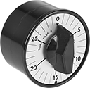
Install these switches in a panel cutout to automatically turn electrical equipment on or off after a set interval.
| No. of Circuits Controlled | Switch Starting Position | Switching Current @ Voltage | Set Time | Input Voltage | Dia. | Dp. | For Panel Cutout Dia. | For Max. Panel Thick. | Wire Connection Type | No. of Terminals | Each | |
Dial Reset | ||||||||||||
|---|---|---|---|---|---|---|---|---|---|---|---|---|
| 1 | 1 Off (Normally Open) or 1 On (Normally Closed) | 20 A @ 120 V AC/240 V AC | 1 min.-15 min. | 120V AC/240V AC | 2 9/16" | 1 9/16" | 13/32" | 1/8" | Screw Terminals | 3 | 0000000 | 0000000 |
| 1 | 1 Off (Normally Open) or 1 On (Normally Closed) | 20 A @ 120 V AC/240 V AC | 1 min.-30 min. | 120V AC/240V AC | 2 3/4" | 1 5/8" | 2 19/32" | 1/4" | Screw Terminals | 3 | 0000000 | 000000 |
| Replacement Knob for 20A Switches | 0000000 | Each | 00000 |
Cable-Pull Emergency Stop Switches
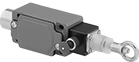
Immediately cut power by pulling a cable. These switches are often used to turn off production lines and material handling systems in an emergency. All have positive-force, snap-open contacts that open a circuit when actuated, even if a spring fails or the contacts stick. The contacts will remain open until you tension the cable and reset the switch.
Switches with a power indicator illuminate when the cable has been pulled.
Switches with a tension indicator let you visually confirm that tension is set correctly in the system.
Accessory kits (sold separately) simplify the installation of a new switch.
Switches | ||||||||||||||||
|---|---|---|---|---|---|---|---|---|---|---|---|---|---|---|---|---|
Mounting | Accessory Kits | |||||||||||||||
| For Max. Cable Lg., ft. | No. of Circuits Controlled | Switch Starting Position | No. of Terminals | Industry Designation | Switching Current @ Voltage | Max. Voltage | Actuation Force, lbs. | Conduit Trade Size | Fasteners Included | No. of Holes | Hole Dia. | Each | Includes | Each | ||
With Screw Terminals | ||||||||||||||||
1 Direction (IP65, NEMA 4) | ||||||||||||||||
| 30 | 1 | 1 Off (Normally Open) or 1 On (Normally Closed) | 3 | SPDT | 10 A @ 120 V AC | 380V AC | 27 | 1/2 | No | 4 | 1/4" | 00000000 | 0000000 | Cable, Clamps, Tension Screws, Thimbles | 00000000 | 0000000 |
1 Direction with Power Indicator and Tension Indicator (IP67, NEMA 4, NEMA 13) | ||||||||||||||||
| 250 | 1 | 1 Off (Normally Open) or 1 On (Normally Closed) | 3 | SPDT | 6 A @ 120 V AC, 2.8 A @ 24 V DC | 300V AC/250V DC | 40 | 1/2 | No | 4 | 1/4" | 00000000 | 000000 | __ | 000000 | 00 |
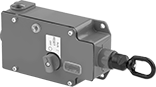
Hazardous Location Cable-Pull Emergency Stop Switches
Safe to use near ignitable gases and dust, the housing on these switches seals in anything that could ignite flammable material. All are UL listed and CSA certified for use in hazardous locations. Yank the cable anywhere along your line to quickly cut power in emergencies. They have positive-force, snap-open contacts that open a circuit when actuated, even if a spring fails or the contacts stick. The contacts will remain open until you tension the cable and reset the switch. Use the tension indicator to visually confirm that they’re reset correctly.
![]() For technical drawings and 3-D models, click on a part number.
For technical drawings and 3-D models, click on a part number.
Mounting | ||||||||||||||
|---|---|---|---|---|---|---|---|---|---|---|---|---|---|---|
| For Max. Cable Lg., ft. | No. of Circuits Controlled | Switch Starting Position | No. of Terminals | Industry Designation | Switching Current @ Voltage | Max. Voltage | Actuation Force, lbs. | Conduit Trade Size | Fasteners Included | Hole Dia. (No. of Holes) | Hole Thread Size (No. of Holes) | Features | Each | |
With Screw Terminals | ||||||||||||||
1 Direction (NEMA 4; NEMA 7; NEMA 9; NEMA 13; NEC Class I Divisions 1, 2 Groups B, C, D; NEC Class II Divisions 1, 2 Groups E, F, G) | ||||||||||||||
| 200 | 1 | 1 Off (Normally Open) or 1 On (Normally Closed) | 3 | SPDT | 10 A @ 600 V AC, 10 A @ 250 V DC | 250V DC/600V AC | 25 | 1/2 | No | 1/4" (2) | 5/16"-18 (2) | Tension Indicator | 0000000 | 000000000 |
Battery Knob Switches

Alternate between two batteries without interrupting power. These switches are often used in marine applications.
![]() For technical drawings and 3-D models, click on a part number.
For technical drawings and 3-D models, click on a part number.
Mounting Holes | |||||||||||||||
|---|---|---|---|---|---|---|---|---|---|---|---|---|---|---|---|
| Actuator Material | No. of Terminals | Max. Voltage | Max. Continuous Current | Terminal Size | For Max. Wire Ga. | No. of | Dia. | Ht. | Wd. | Dp. | Environment | Environmental Rating | Specifications Met | Each | |
With Stud Terminals | |||||||||||||||
For 3 5/8" Cutout Dia. | |||||||||||||||
| Plastic | 3 | 32V DC | 350 A @ 32 V DC | 3/8" | 4/0 | 4 | 1/4" | 3 7/8" | 3 7/8" | 3 1/8" | Washdown | IP66 | UL Listed, UL Marine Listed, CE Marked, ISO 8846, SAE J1171 | 00000000 | 000000 |
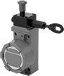
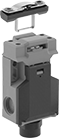
Frame-Mounted Safety Switches
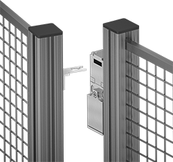
Also known as interlock switches, these ensure the safety of personnel by automatically shutting off power to machinery when an access door opens. Mount the switch to the door frame and mount a key to the door so that the key is inserted into the switch when the door is closed. When the door opens, the key is removed from the switch and the machine shuts down. They’re often used with machine guards for large robots.
All switches require an actuator key, but not all include one—check whether you need to pick out a separate actuator key. For some switch styles, you can also select the mounting orientation of the key.
Style A-G switches have positive-force, normally closed contacts that will open a circuit when the switch is actuated even if a spring fails or the contacts stick.
IP67 rated switches protect against temporary submersion.
![]() For technical drawings and 3-D models, click on a part number.
For technical drawings and 3-D models, click on a part number.
Housing | Conduit | |||||||||||||||
|---|---|---|---|---|---|---|---|---|---|---|---|---|---|---|---|---|
| Style | No. of Circuits Controlled | Switch Starting Position | Switch Action | No. of Terminals | Industry Designation | Switching Current @ Voltage | Max. Voltage | Ht. | Wd. | Dp. | Trade Size | Thread Type | Key Included | Environmental Rating | Each | |
Screw Terminal Connection with Positive-Force Normally Closed Contacts | ||||||||||||||||
| C | 3 | 1 Off (Normally Open) and 2 On (Normally Closed) | Stays Switched (Maintained) | 3 | 3PST-1NO/2NC | 8 A @ 120 V AC, 4 A @ 24 V DC | 600V AC 250V DC | 3.5" | 2.1" | 1.2" | 1/2 | NPT | Yes | IP67 | 00000000 | 0000000 |