


Choosing an Electrical Switch
More
Toggle Light Switches
Your standard light switches—these switches stick out of your mounting surface and flip on and off. They also work with AC motor loads up to 80% of the current rating. All fit standard wall plates (not included).
Illuminated switches light up when switched off so you can find them in the dark.
Switches with spring clamp terminals install quicker than those with screw terminals. To install, push stripped wire into the clamp for a secure connection.
Switches with a power indicator have a light that shows you when they’re on. This is helpful when you've connected them to something other than lighting, such as an outlet.
Wall switch lockouts (sold separately) mount over switches to secure them in the on or off position.


Terminals and
Power Indicator
| No. of Circuits Controlled | No. of Terminals | Switch Action | Switching Current @ Voltage | Wire Connection Type | Terminal Location | Features | Choose a Color | Each | |
Not Illuminated | |||||||||
|---|---|---|---|---|---|---|---|---|---|
| 1 | 2 | Stays Switched (Maintained) | 15 A @ 120 V AC/277 V AC | Screw Terminals | Back, Side | __ | 0000000 | 00000 | |
| 1 | 2 | Stays Switched (Maintained) | 15 A @ 120 V AC/277 V AC | Spring-Clamp Terminals | Back | __ | 00000000 | 00000 | |
| 1 | 2 | Stays Switched (Maintained) | 15 A @ 120 V AC | Screw Terminals | Side | Power Indicator | 00000000 | 00000 | |
| 1 | 2 | Stays Switched (Maintained) | 20 A @ 120 V AC/277 V AC | Screw Terminals | Back, Side | __ | 0000000 | 0000 | |
| 1 | 2 | Stays Switched (Maintained) | 20 A @ 120 V AC/277 V AC | Spring-Clamp Terminals | Back | __ | 00000000 | 00000 | |
| 1 | 2 | Stays Switched (Maintained) | 20 A @ 120 V AC | Screw Terminals | Side | Power Indicator | 00000000 | 00000 | |
| 1 | 2 | Stays Switched (Maintained) | 30 A @ 120 V AC/277 V AC | Screw Terminals | Back, Side | __ | 0000000 | 00000 | |
Illuminated | |||||||||
| 1 | 2 | Stays Switched (Maintained) | 15 A @ 120 V AC/277 V AC | Screw Terminals | Back, Side | __ | Ivory | 0000000 | 00000 |
| 1 | 2 | Stays Switched (Maintained) | 15 A @ 120 V AC | Screw Terminals | Back, Side | __ | Clear | 0000000 | 00000 |
| 1 | 2 | Stays Switched (Maintained) | 20 A @ 120 V AC/277 V AC | Screw Terminals | Back, Side | __ | Ivory | 0000000 | 00000 |
| 1 | 2 | Stays Switched (Maintained) | 20 A @ 120 V AC | Screw Terminals | Back, Side | __ | Clear | 0000000 | 00000 |

Overall | ||||||||||
|---|---|---|---|---|---|---|---|---|---|---|
| For Max. No. of Padlocks | For Max. Padlock Shackle Dia. | Lg. | Wd. | Dp. | Color | Language | Message | Specifications Met | Each | |
| 1 | 9/32" | 4 3/4" | 1 3/4" | 1" | Red | English/Spanish, English/French | Danger—Locked Out Do Not Remove, Peligro—Cerrado No Lo Quite, Danger—Locked Out Do Not Remove, Danger—Verrouille Ne Pas Enlever | OSHA Compliant 29 CFR 1910.147 | 00000000 | 000000 |
Toggle Light Switch/Receptacles
No need for separate outlet boxes—these combine a switch and a receptacle into a single box.
![]() For technical drawings and 3-D models, click on a part number.
For technical drawings and 3-D models, click on a part number.
Rocker Light Switches
Similar to a seesaw, these switches have an actuator that pivots when pressed to turn them on or off. They’re often used to control lighting, but they also work with AC motor loads up to 80% of the current rating. All fit standard wall plates (not included) and won’t stick out from your wall as much as toggle light switches.
Switches with spring-clamp terminals are quicker to install than those with screw terminals. Just push your bare wires into the connectors.
Illuminated switches glow when turned off, making them easy to spot in the dark.
Switches with a power indicator glow when activated. This means you can see whether a device or outlet is powered directly on the switch even if they’re in different rooms.
Wall switch lockouts (sold separately) mount over switches to secure them in the on or off position.
![]() For technical drawings and 3-D models, click on a part number.
For technical drawings and 3-D models, click on a part number.
Terminals and
Power Indicator
| No. of Circuits Controlled | No. of Terminals | Switch Action | Switching Current @ Voltage | Terminal Location | Features | Specifications Met | Choose a Color | Each | |
WIth Screw Terminals | |||||||||
|---|---|---|---|---|---|---|---|---|---|
Not Illuminated | |||||||||
| 1 | 2 | Stays Switched (Maintained) | 15 A @ 120 V AC/277 V AC | Back, Side | __ | UL Listed, CSA Certified | 0000000 | 00000 | |
| 1 | 2 | Stays Switched (Maintained) | 15 A @ 120 V AC | Side | Power Indicator | UL Listed, CSA Certified | 0000000 | 00000 | |
| 1 | 2 | Stays Switched (Maintained) | 20 A @ 120 V AC/277 V AC | Back, Side | __ | UL Listed, CSA Certified | 0000000 | 0000 | |
Illuminated | |||||||||
| 1 | 2 | Stays Switched (Maintained) | 15 A @ 120 V AC | Side | __ | UL Listed, C-UL Listed | 0000000 | 00000 | |
With Spring-Clamp Terminals | |||||||||
Not Illuminated | |||||||||
| 1 | 2 | Stays Switched (Maintained) | 15 A @ 120 V AC/277 V AC | Back | __ | UL Listed, C-UL Listed, CSA Certified | 0000000 | 00000 | |
| 1 | 2 | Stays Switched (Maintained) | 20 A @ 120 V AC/277 V AC | Back | __ | UL Listed, C-UL Listed, CSA Certified | 0000000 | 00000 | |
Illuminated | |||||||||
| 1 | 2 | Stays Switched (Maintained) | 20 A @ 120 V AC/277 V AC | Back | __ | UL Listed, C-UL Listed, CSA Certified | 0000000 | 00000 | |
Overall | ||||||||||
|---|---|---|---|---|---|---|---|---|---|---|
| For Max. No. of Padlocks | For Max. Padlock Shackle Dia. | Lg. | Wd. | Dp. | Color | Language | Message | Specifications Met | Each | |
| 1 | 9/32" | 4 3/4" | 1 3/4" | 1" | Red | English/Spanish, English/French | Danger—Locked Out Do Not Remove, Peligro—Cerrado No Lo Quite, Danger—Locked Out Do Not Remove, Danger—Verrouille Ne Pas Enlever | OSHA Compliant 29 CFR 1910.147 | 00000000 | 000000 |
Outdoor Rocker Light Switches

Switch lights on and off no matter the forecast. NEMA 3R rated, these switches have a gasket that blocks out weather. They are rocker switches, so they protrude less off your wall than other switches.
| No. of Circuits Controlled | No. of Terminals | Switch Action | Switching Current @ Voltage | Wire Connection Type | Terminal Location | Environmental Rating | Specifications Met | Choose a Color | Each | |
| 1 | 2 | Stays Switched (Maintained) | 20 A @ 120 V AC/277 V AC | Screw Terminals | Back, Side | NEMA 3R | UL Listed, C-UL Listed | 0000000 | 000000 |
Rocker Light Switches/Receptacles
Combine a switch and receptacle into a single outlet box for a small footprint. The rocker switch is low-profile, so it protrudes off the wall less than other switches.
![]() For technical drawings and 3-D models, click on a part number.
For technical drawings and 3-D models, click on a part number.
Key-Actuated Light Switches

Prevent accidental activation—these switches require a key to turn lights on and off. They’re keyed alike, so all switches actuate with the same key. They also work with AC motor loads up to 80% of the current rating. All fit standard wall plates (not included).
![]() For technical drawings and 3-D models, click on a part number.
For technical drawings and 3-D models, click on a part number.
| No. of Circuits Controlled | Color | Key Removal Position | No. of Keys Included | No. of Terminals | Switch Action | Switching Current @ Voltage | Wire Connection Type | Terminal Location | Each | |
| 1 | Gray | Off, On | 1 | 2 | Stays Switched (Maintained) | 15 A @ 120 V AC/277 V AC | Screw Terminals | Back, Side | 0000000 | 000000 |
| 1 | Gray | Off, On | 1 | 2 | Stays Switched (Maintained) | 20 A @ 120 V AC/277 V AC | Screw Terminals | Back, Side | 0000000 | 00000 |
| Replacement Key | 0000000 | Each | 00000 |
Light Dimmers


Adjust the brightness of lights.
Toggle switches stay put in any position; move the toggle up and down to increase and decrease lighting level.
Rocker switches with slide dimmers and mini slide dimmers turn lights on and off with a separate rocker actuator to maintain a desired lighting level.
| For Bulb Type | No. of Circuits Controlled | No. of Terminals | Input Voltage | Wattage | Wire Connection Type | Choose a Color | Each | |
Rotary with Wall Plate | ||||||||
|---|---|---|---|---|---|---|---|---|
| Incandescent | 1 | 2 | 120V AC | 1,500W | Wire Leads | 0000000 | 0000000 | |
| Incandescent | 1 | 2 | 120V AC | 2,000W | Wire Leads | 0000000 | 000000 | |
Toggle | ||||||||
| Incandescent | 1 | 2 | 120V AC | 600W | Screw Terminals | Ivory | 0000000 | 00000 |
Rocker with Slide Dimmer | ||||||||
| Incandescent and Halogen | 1 | 2 | 120V AC | 1,000W | Wire Leads | 0000000 | 00000 | |
Rocker with Mini Slide Dimmer | ||||||||
| Incandescent and Halogen | 1 | 2 | 120V AC | 1,000W | Screw Terminals | 0000000 | 00000 | |
| Incandescent and Halogen or CFL and LED | 1 | 2 | 120V AC | 600W/150W | Screw Terminals | White | 0000000 | 00000 |
Panel-Mount Timer Switches

Install these switches in a panel cutout to automatically turn electrical equipment on or off after a set interval.
Switches with set time recall retain the last setting; push the button to start the timer over at the same interval, eliminating the need to reset the dial with every use.
Wire Leads | ||||||||||||||
|---|---|---|---|---|---|---|---|---|---|---|---|---|---|---|
| No. of Circuits Controlled | Switch Starting Position | Switching Current @ Voltage | Set Time | Input Voltage | Dia. | Dp. | For Panel Cutout Dia. | For Max. Panel Thick. | Wire Connection Type | No. of Terminals | No. of | Lg. | Each | |
Dial Reset | ||||||||||||||
| 1 | 1 Off (Normally Open) or 1 On (Normally Closed) | 15 A @ 125 V AC/250 V AC | 1 min.-30 min. | 120V AC | 3 1/16" | 1 13/16" | 3/8" | 1/8" | Quick-Disconnect Terminals/Wire Leads | 2 | 2 | 8" | 0000000 | 0000000 |
| 1 | 1 Off (Normally Open) or 1 On (Normally Closed) | 15 A @ 125 V AC/250 V AC | 1 hrs.-12 hrs. | 120V AC | 3 1/16" | 1 13/16" | 3/8" | 1/8" | Quick-Disconnect Terminals/Wire Leads | 2 | 2 | 8" | 0000000 | 000000 |
| 1 | 1 Off (Normally Open) or 1 On (Normally Closed) | 15 A @ 125 V AC/250 V AC | 1 hrs.-60 hrs. | 120V AC | 3 1/16" | 1 13/16" | 3/8" | 1/8" | Quick-Disconnect Terminals/Wire Leads | 2 | 2 | 8" | 0000000 | 000000 |
| 1 | 1 Off (Normally Open) or 1 On (Normally Closed) | 15 A @ 125 V AC/250 V AC | 2 hrs.-24 hrs. | 120V AC | 3 1/16" | 1 13/16" | 3/8" | 1/8" | Quick-Disconnect Terminals/Wire Leads | 2 | 2 | 8" | 0000000 | 000000 |
| 1 | 1 Off (Normally Open) or 1 On (Normally Closed) | 15 A @ 125 V AC/250 V AC | 5 min.-60 min. | 120V AC | 3 1/16" | 1 13/16" | 3/8" | 1/8" | Quick-Disconnect Terminals/Wire Leads | 2 | 2 | 8" | 0000000 | 000000 |
Push Reset with Set Time Recall | ||||||||||||||
| 1 | 1 Off (Normally Open) or 1 On (Normally Closed) | 15 A @ 125 V AC/250 V AC | 1 min.-30 min. | 120V AC | 3 1/16" | 2 1/8" | 3/8" | 1/8" | Quick-Disconnect Terminals/Wire Leads | 2 | 2 | 8" | 0000000 | 000000 |
| 1 | 1 Off (Normally Open) or 1 On (Normally Closed) | 15 A @ 125 V AC/250 V AC | 1 hrs.-12 hrs. | 120V AC | 3 1/16" | 2 1/8" | 3/8" | 1/8" | Quick-Disconnect Terminals/Wire Leads | 2 | 2 | 8" | 0000000 | 000000 |
| 1 | 1 Off (Normally Open) or 1 On (Normally Closed) | 15 A @ 125 V AC/250 V AC | 1 hrs.-60 hrs. | 120V AC | 3 1/16" | 2 1/8" | 3/8" | 1/8" | Quick-Disconnect Terminals/Wire Leads | 2 | 2 | 8" | 0000000 | 000000 |
| 1 | 1 Off (Normally Open) or 1 On (Normally Closed) | 15 A @ 125 V AC/250 V AC | 2 hrs.-24 hrs. | 120V AC | 3 1/16" | 2 1/8" | 3/8" | 1/8" | Quick-Disconnect Terminals/Wire Leads | 2 | 2 | 8" | 0000000 | 000000 |
| 1 | 1 Off (Normally Open) or 1 On (Normally Closed) | 15 A @ 125 V AC/250 V AC | 5 min.-60 min. | 120V AC | 3 1/16" | 2 1/8" | 3/8" | 1/8" | Quick-Disconnect Terminals/Wire Leads | 2 | 2 | 8" | 0000000 | 000000 |
Enclosure Door Switches
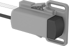
Activate or deactivate fans, lights, and other devices inside your enclosure when you open or close the door. To actuate these switches, push the plunger. They work with most enclosures, since you can slide the housing up to 1 3/8” to make the switch longer or shorter. Mount screws anywhere along the mounting slots to install.
Normally closed switches set off an alarm, light, or other device when you open the door.
![]() For technical drawings and 3-D models, click on a part number.
For technical drawings and 3-D models, click on a part number.
Switching | For Wire | ||||||||||||
|---|---|---|---|---|---|---|---|---|---|---|---|---|---|
| Number of Circuits Controlled | Switch Action | Number of Terminals | Industry Designation | Current, A | Voltage | Maximum Voltage | Gauge | Number of | Overall Length | Environmental Rating | Specifications Met | Each | |
Plastic Actuator with Wire Leads | |||||||||||||
1 On (Normally Closed) | |||||||||||||
| 1 | Springs Back (Momentary) | 2 | SPST-NC | 8 | 250V AC | 250V AC | 16-14 | 2 | 4 1/4" | IP20 | CE Marked | 0000000 | 000000 |
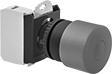
Vibration-Resistant 22 mm Panel-Mount Lever Switches

Prevent accidental actuation from bumps—these switches require you to grip and twist the lever to turn the switch. The contact block and actuator are all one piece, so they won’t separate in high-vibration applications. Install them in a standard panel cutout.
![]() For technical drawings and 3-D models, click on a part number.
For technical drawings and 3-D models, click on a part number.
| Lever Lg. | No. of Circuits Controlled | Switch Starting Position | Switch Action | No. of Terminals | Industry Designation | Switching Current @ Voltage | Max. Voltage | Dia. | Dp. Behind Panel | Environmental Rating | Specifications Met | Each | |
2 Position with Screw Terminals | |||||||||||||
|---|---|---|---|---|---|---|---|---|---|---|---|---|---|
| 1 1/8" | 1 | 1 Off (Normally Open) | Stays Switched (Maintained) | 2 | SPST-NO | 0.6 A @ 120 V AC, 0.22 A @ 125 V DC | 240V AC 250V DC | 1 1/8" | 1 11/16" | NEMA 3, NEMA 12, IP65 | UL Listed, UL 508, CSA Certified, CCC Marked, CE Marked | 0000000 | 000000 |
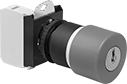
Plastic 22 mm Emergency Stop Panel-Mount Push-Button Switches
Immediately cut power with a single push. These switches meet EN 418 for compliance with European machine directives for emergency stop applications. All have positive force contacts that will open a circuit when actuated even if a spring fails or the contacts stick. They're rated IP66, IP69K, NEMA 3S, NEMA 4X, and NEMA 13, and are UL and C-UL Recognized Components. Switches include enough contact blocks to control the number of circuits listed. Contact blocks are rated IP20 and are UL and C-UL Listed.
Key reset switches are keyed alike, so if you buy multiple switches they will all reset with the same key.
Additional contact blocks (sold separately) can be added to control more circuits, or replace the included contact block.
![]() For technical drawings and 3-D models, click on a part number.
For technical drawings and 3-D models, click on a part number.
Switches | Replacement Actuators | |||||||||||||||
|---|---|---|---|---|---|---|---|---|---|---|---|---|---|---|---|---|
| No. of Circuits Controlled | Switch Starting Position | Switch Action | No. of Terminals | Industry Designation | Actuator Color | Switching Current @ Voltage | Max. Voltage | Dia. | Dp. Behind Panel | For Max. No. of Contact Blocks | No. of Keys Included | Manufacturer | Each | Each | ||
With Screw Terminals | ||||||||||||||||
Pull Reset | ||||||||||||||||
| 1 | 1 On (Normally Closed) | Stays Switched (Maintained) | 2 | SPST-NC | Red | 6 A @ 120 V AC, 2.5 A @ 24 V DC | 600V AC 600V DC | 1 1/4" | 1 13/16" | 6 | __ | BACO Controls | 0000000 | 000000 | 000000 | 00 |
| 1 | 1 On (Normally Closed) | Stays Switched (Maintained) | 2 | SPST-NC | Red | 6 A @ 120 V AC, 2.5 A @ 24 V DC | 600V AC 600V DC | 1 9/16" | 1 13/16" | 6 | __ | BACO Controls | 0000000 | 00000 | 0000000 | 000000 |
Key Reset | ||||||||||||||||
| 1 | 1 On (Normally Closed) | Stays Switched (Maintained) | 2 | SPST-NC | Red | 6 A @ 120 V AC, 2.5 A @ 24 V DC | 600V AC 600V DC | 1 1/4" | 1 13/16" | 6 | 2 | BACO Controls | 0000000 | 00000 | 000000 | 00 |
| 1 | 1 On (Normally Closed) | Stays Switched (Maintained) | 2 | SPST-NC | Red | 6 A @ 120 V AC, 2.5 A @ 24 V DC | 600V AC 600V DC | 1 9/16" | 1 13/16" | 6 | 2 | BACO Controls | 0000000 | 00000 | 0000000 | 000000 |
Turn Reset | ||||||||||||||||
| 1 | 1 On (Normally Closed) | Stays Switched (Maintained) | 2 | SPST-NC | Red | 6 A @ 120 V AC, 2.5 A @ 24 V DC | 600V AC 600V DC | 1 9/16" | 1 13/16" | 6 | __ | BACO Controls | 0000000 | 00000 | 0000000 | 00000 |
| Emergency Stop Label | 0000000 | Each | 000000 |

| No. of Circuits Controlled | Switch Starting Position | No. of Terminals | Industry Designation | Each | |
| 1 | 1 On (Normally Closed) | 2 | SPST-NC | 000000 | 00000 |
Metal 22 mm Emergency Stop Panel-Mount Push-Button Switches
Immediately cut power with a single push. These switches meet EN 418 for compliance with European machine directives for emergency stop applications. All have positive force contacts that will open a circuit when actuated even if a spring fails or the contacts stick. They include enough contact blocks to control the number of circuits listed.
Pull reset, illuminated pull reset, and turn reset switches are rated NEMA 4, 13, and IP66. Contact blocks for these switches are rated IP20.
Note: Illuminated switches include a bulb. If wiring the switch and the bulb to the same circuit, the circuit voltage must not exceed bulb voltage.
Additional contact blocks (sold separately) can be added to control more circuits, or replace the included contact block.
![]() For technical drawings and 3-D models, click on a part number.
For technical drawings and 3-D models, click on a part number.


| No. of Circuits Controlled | Switch Starting Position | Switch Action | No. of Terminals | Industry Designation | Actuator Color | Switching Current @ Voltage | Max. Voltage | Dia. | Dp. Behind Panel | For Max. No. of Contact Blocks | Choose a Bulb Voltage | Each | |
Key Reset with Screw Terminals | |||||||||||||
|---|---|---|---|---|---|---|---|---|---|---|---|---|---|
| 1 | 1 On (Normally Closed) | Stays Switched (Maintained) | 2 | SPST-NC | Red | 6 A @ 120 V AC, 2.5 A @ 24 V DC | 600V AC 600V DC | 1 9/16" | 1 13/16" | 6 | __ | 00000000 | 000000 |
Pull Reset with Screw Terminals | |||||||||||||
| 1 | 1 On (Normally Closed) | Stays Switched (Maintained) | 2 | SPST-NC | Red | 6 A @ 120 V AC, 2.5 A @ 24 V DC | 600V AC 600V DC | 1 9/16" | 1 13/16" | 6 | __ | 0000000 | 00000 |
Pull Reset with Screw Terminals—Illuminated | |||||||||||||
| 1 | 1 On (Normally Closed) | Stays Switched (Maintained) | 2 | SPST-NC | Red | 6 A @ 120 V AC, 2.5 A @ 24 V DC | 600V AC 600V DC | 1 3/16" | 1 13/16" | 4 | 0000000 | 00000 | |
| 1 | 1 On (Normally Closed) | Stays Switched (Maintained) | 2 | SPST-NC | Red | 6 A @ 120 V AC, 2.5 A @ 24 V DC | 600V AC 600V DC | 1 9/16" | 1 13/16" | 4 | 0000000 | 000000 | |
Turn Reset with Screw Terminals | |||||||||||||
| 1 | 1 On (Normally Closed) | Stays Switched (Maintained) | 2 | SPST-NC | Red | 6 A @ 120 V AC, 2.5 A @ 24 V DC | 600V AC 600V DC | 1 3/16" | 1 13/16" | 6 | __ | 00000000 | 00000 |
| 1 | 1 On (Normally Closed) | Stays Switched (Maintained) | 2 | SPST-NC | Red | 6 A @ 120 V AC, 2.5 A @ 24 V DC | 600V AC 600V DC | 1 9/16" | 1 13/16" | 6 | __ | 0000000 | 00000 |
| 1 | 1 On (Normally Closed) | Stays Switched (Maintained) | 2 | SPST-NC | Red | 6 A @ 120 V AC, 2.5 A @ 24 V DC | 600V AC 600V DC | 2 3/8" | 1 13/16" | 6 | __ | 00000000 | 00000 |
Turn Reset with Screw Terminals—Illuminated | |||||||||||||
| 1 | 1 On (Normally Closed) | Stays Switched (Maintained) | 2 | SPST-NC | Red | 6 A @ 120 V AC, 2.5 A @ 24 V DC | 600V AC 600V DC | 1 9/16" | 1 13/16" | 4 | 0000000 | 00000 | |
| Emergency Stop Label for Switch without Lockout | 0000000 | Each | 00000 |

Make or break an electrical circuit. These contact blocks mount to manual switches and transmit an electrical signal when the switch actuator is engaged. You can stack multiple blocks, so a single switch can control several circuits. This is helpful in setups that require multiple systems to turn on or off at the same time. For example, the switch on a conveyor line could turn off the conveyor and turn on a diverter and alarm.
16 mm Emergency Stop Panel-Mount Push-Button Switches


Immediately cut power with a single push. These switches meet EN 418 for compliance with European machine directives for emergency stop applications. They're rated NEMA 4, 13, and IP65 for protection from washdowns and oil/coolant spraying.
Key reset switches are keyed alike, so if you buy multiple switches they will all reset with the same key.
| No. of Circuits Controlled | Switch Starting Position | Switch Action | No. of Terminals | Industry Designation | Actuator Color | Switching Current @ Voltage | Max. Voltage | Dia. | Dp. Behind Panel | For Max. No. of Contact Blocks | No. of Keys Included | Each | |
Plastic Actuator with Screw Terminals | |||||||||||||
|---|---|---|---|---|---|---|---|---|---|---|---|---|---|
Key Reset | |||||||||||||
| 1 | 1 On (Normally Closed) | Stays Switched (Maintained) | 2 | SPST-NC | Red | 2.5 A @ 125 V AC, 6 A @ 24 V DC | 250V AC | 1 1/16" | 1 11/16" | 1 | 2 | 00000000 | 0000000 |
Turn Reset | |||||||||||||
| 1 | 1 On (Normally Closed) | Stays Switched (Maintained) | 2 | SPST-NC | Red | 2.5 A @ 125 V AC, 6 A @ 24 V DC | 250V AC | 1 1/16" | 1 11/16" | 1 | __ | 00000000 | 000000 |
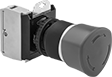
30 mm Emergency Stop Panel-Mount Push-Button Switches
Immediately cut power with a single push. These switches are rated for protection from low-pressure streams of water and oil/coolant spraying. They have positive force contacts that will open a circuit when actuated even if a spring fails or the contacts stick. Mount them in a standard panel cutout.
Turn twist switches back on by twisting the button and pull switches by pulling it. Add an optional lockout (sold separately) on either kind to cover the button and prevent changes to its position.
Additional contact blocks (sold separately) can be added to control more circuits or replace the included contact blocks.


| No. of Circuits Controlled | Switch Starting Position | Switch Action | No. of Terminals | Industry Designation | Actuator Color | Switching Current @ Voltage | Max. Voltage | Dia. | Dp. Behind Panel | For Max. No. of Contact Blocks | Each | |
Metal Base with Screw Terminals | ||||||||||||
|---|---|---|---|---|---|---|---|---|---|---|---|---|
Pull Reset | ||||||||||||
| 1 | 1 On (Normally Closed) | Stays Switched (Maintained) | 2 | SPST-NC | Red | 6 A @ 120 V AC, 5 A @ 24 V DC | 250V DC 600V AC | 1 1/2" | 1 1/2" | 8 | 00000000 | 000000 |
| 1 | 1 On (Normally Closed) | Stays Switched (Maintained) | 2 | SPST-NC | Red | 6 A @ 120 V AC, 5 A @ 24 V DC | 250V DC 600V AC | 2 1/4" | 1 1/2" | 8 | 00000000 | 000000 |
| 1 | 1 On (Normally Closed) | Stays Switched (Maintained) | 2 | SPST-NC | Red | 6 A @ 120 V AC, 2.5 A @ 24 V DC | 600V AC 600V DC | 1 5/8" | 2 3/4" | 4 | 000000 | 000000 |
Twist Reset | ||||||||||||
| 1 | 1 On (Normally Closed) | Stays Switched (Maintained) | 2 | SPST-NC | Red | 6 A @ 120 V AC, 5 A @ 24 V DC | 250V DC 600V AC | 1 1/2" | 1 1/2" | 8 | 00000000 | 000000 |
Plastic Base with Screw Terminals | ||||||||||||
Pull Reset | ||||||||||||
| 1 | 1 On (Normally Closed) | Stays Switched (Maintained) | 2 | SPST-NC | Red | 6 A @ 120 V AC, 5 A @ 24 V DC | 250V DC 600V AC | 1 1/2" | 1 1/2" | 8 | 00000000 | 00000 |
| 1 | 1 On (Normally Closed) | Stays Switched (Maintained) | 2 | SPST-NC | Red | 6 A @ 120 V AC, 5 A @ 24 V DC | 250V DC 600V AC | 2 1/4" | 1 1/2" | 8 | 00000000 | 000000 |
Twist Reset | ||||||||||||
| 1 | 1 On (Normally Closed) | Stays Switched (Maintained) | 2 | SPST-NC | Red | 6 A @ 120 V AC, 5 A @ 24 V DC | 250V DC 600V AC | 1 1/2" | 1 1/2" | 8 | 00000000 | 00000 |
| No. of Circuits Controlled | Switch Starting Position | No. of Terminals | Industry Designation | Environmental Rating | Specifications Met | Each | |
For 1 1/2" and 2 1/4" Diameter Switches | |||||||
|---|---|---|---|---|---|---|---|
| 1 | 1 Off (Normally Open) | 2 | SPST-NO | __ | UL Listed, CSA Certified, CE Marked, C-UL Listed, UL 508, EN 60947-5-1, EN 60947-1 | 00000000 | 000000 |
| 1 | 1 On (Normally Closed) | 2 | SPST-NC | __ | UL Listed, CSA Certified, CE Marked, C-UL Listed, UL 508, EN 60947-5-1, EN 60947-1 | 00000000 | 00000 |
For 1 5/8" Diameter Switches | |||||||
| 1 | 1 On (Normally Closed) | 2 | SPST-NC | IP20 | CSA Certified, IEC 60947-1, IEC 60947-5-1, EN 60947-5-1, EN 60947-1, EN 60947-5-4, IEC 60947-5-4 | 0000000 | 00000 |


| Actuator Clarity | Actuator Color | Each | |
For Non-Illuminated Switches | |||
|---|---|---|---|
| Opaque | Red | 00000000 | 000000 |

| For Maximum Padlock Shackle Diameter | Each | |
| 1/4" | 00000000 | 000000 |
Frame-Mounted Safety Switches
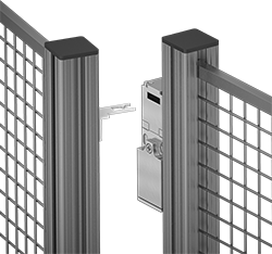
Also known as interlock switches, these ensure the safety of personnel by automatically shutting off power to machinery when an access door opens. Mount the switch to the door frame and mount a key to the door so that the key is inserted into the switch when the door is closed. When the door opens, the key is removed from the switch and the machine shuts down. They’re often used with machine guards for large robots.
All switches require an actuator key, but not all include one—check whether you need to pick out a separate actuator key. For some switch styles, you can also select the mounting orientation of the key.
Style A-G switches have positive-force, normally closed contacts that will open a circuit when the switch is actuated even if a spring fails or the contacts stick.
IP67 rated switches protect against temporary submersion.
![]() For technical drawings and 3-D models, click on a part number.
For technical drawings and 3-D models, click on a part number.
Housing | Conduit | |||||||||||||||
|---|---|---|---|---|---|---|---|---|---|---|---|---|---|---|---|---|
| Style | No. of Circuits Controlled | Switch Starting Position | Switch Action | No. of Terminals | Industry Designation | Switching Current @ Voltage | Max. Voltage | Ht. | Wd. | Dp. | Thread Size | Thread Type | Key Included | Environmental Rating | Each | |
Wire Lead Connection with Positive-Force Normally Closed Contacts | ||||||||||||||||
| A | 2 | 1 Off (Normally Open) and 1 On (Normally Closed) | Stays Switched (Maintained) | 2 | DPST-1NO/1NC | 8 A @ 120 V AC, 4 A @ 24 V DC | 250V AC 24V DC | 3.3" | 1.2" | 1.2" | M16 | Metric | Yes | IP67 | 00000000 | 0000000 |