


Positioning Slides


Use these slides in a variety of manual-positioning applications for laboratory and production equipment as well as for positioning parts for drilling, fastening, assembly, and measuring. Their Rulon sleeve bearings allow smooth movement in dirty environments.
Travel distance per turn, also known as screw lead, is the distance the carriage moves with one revolution of the handle.
Note: Capacities listed are for horizontal mounting. When mounted vertically, the load capacity is cut in half.
![]() For technical drawings and 3-D models, click on a part number.
For technical drawings and 3-D models, click on a part number.
O'all | Carriage | Handle | Carriage Mounting | Base Mounting | ||||||||||||||
|---|---|---|---|---|---|---|---|---|---|---|---|---|---|---|---|---|---|---|
| Travel Lg. | Travel Distance per Turn | Accuracy for Travel Distance per Turn | Ht. | Wd. | Lg. | Wd. | Lg. | Type | Dia. | Overhang | Max. Temp., °F | No. of Holes | Hole Thread Size | No. of Holes | For Fastener Thread Size | Mounting Fasteners Included | Each | |
Aluminum Carriage and Base | ||||||||||||||||||
15 lbs. Static Load Capacity | ||||||||||||||||||
| 1.5" | 0.05" | 0.0007" per in. | 0.56" | 1.5" | 4.16" | 0.62" | 1.5" | Dial | 0.61" | __ | 180° | 4 | 6-32 | 2 | 8-32 | No | 0000000 | 0000000 |
| 4.5" | 0.05" | 0.0007" per in. | 0.56" | 1.5" | 7.16" | 0.62" | 1.5" | Dial | 0.61" | __ | 180° | 4 | 6-32 | 2 | 8-32 | No | 0000000 | 000000 |
| 7.5" | 0.05" | 0.0007" per in. | 0.56" | 1.5" | 10.16" | 0.62" | 1.5" | Dial | 0.61" | __ | 180° | 4 | 6-32 | 3 | 8-32 | No | 0000000 | 000000 |
| 10.5" | 0.05" | 0.0007" per in. | 0.56" | 1.5" | 13.16" | 0.62" | 1.5" | Dial | 0.61" | __ | 180° | 4 | 6-32 | 4 | 8-32 | No | 0000000 | 000000 |
30 lbs. Static Load Capacity | ||||||||||||||||||
| 1.5" | 0.05" | 0.0007" per in. | 0.81" | 2.5" | 6.72" | 1.25" | 2.5" | Hand Wheel | 1.75" | 0.44" | 180° | 4 | 8-32 | 2 | 10-32 | No | 0000000 | 000000 |
| 3.5" | 0.05" | 0.0007" per in. | 0.81" | 2.5" | 8.72" | 1.25" | 2.5" | Hand Wheel | 1.75" | 0.44" | 180° | 4 | 8-32 | 2 | 10-32 | No | 0000000 | 000000 |
| 6.5" | 0.05" | 0.0007" per in. | 0.81" | 2.5" | 11.72" | 1.25" | 2.5" | Hand Wheel | 1.75" | 0.44" | 180° | 4 | 8-32 | 3 | 10-32 | No | 0000000 | 000000 |
| 9.5" | 0.05" | 0.0007" per in. | 0.81" | 2.5" | 14.72" | 1.25" | 2.5" | Hand Wheel | 1.75" | 0.44" | 180° | 4 | 8-32 | 4 | 10-32 | No | 0000000 | 000000 |
| 12.5" | 0.05" | 0.0007" per in. | 0.81" | 2.5" | 17.72" | 1.25" | 2.5" | Hand Wheel | 1.75" | 0.44" | 180° | 4 | 8-32 | 5 | 10-32 | No | 0000000 | 000000 |
100 lbs. Static Load Capacity | ||||||||||||||||||
| 2" | 0.1" | 0.0007" per in. | 1.06" | 4" | 8.73" | 2.35" | 4" | Hand Wheel | 1.75" | 0.24" | 180° | 4 | 10-32 | 2 | 1/4"-20 | No | 0000000 | 000000 |
| 5" | 0.1" | 0.0007" per in. | 1.06" | 4" | 11.73" | 2.35" | 4" | Hand Wheel | 1.75" | 0.24" | 180° | 4 | 10-32 | 3 | 1/4"-20 | No | 0000000 | 000000 |
| 8" | 0.1" | 0.0007" per in. | 1.06" | 4" | 14.73" | 2.35" | 4" | Hand Wheel | 1.75" | 0.24" | 180° | 4 | 10-32 | 4 | 1/4"-20 | No | 0000000 | 000000 |
| 11" | 0.1" | 0.0007" per in. | 1.06" | 4" | 17.73" | 2.35" | 4" | Hand Wheel | 1.75" | 0.24" | 180° | 4 | 10-32 | 5 | 1/4"-20 | No | 0000000 | 000000 |
| 14" | 0.1" | 0.0007" per in. | 1.06" | 4" | 20.73" | 2.35" | 4" | Hand Wheel | 1.75" | 0.24" | 180° | 4 | 10-32 | 6 | 1/4"-20 | No | 0000000 | 000000 |
| 20" | 0.1" | 0.0007" per in. | 1.06" | 4" | 26.73" | 2.35" | 4" | Hand Wheel | 1.75" | 0.24" | 180° | 4 | 10-32 | 8 | 1/4"-20 | No | 0000000 | 00000000 |
Precision Positioning Slides

A linear scale and micrometer-like hand wheel measure travel distance in increments of 0.001". Rulon sleeve bearings allow these slides to move smoothly, even in dirty environments. Use them in a variety of manual-positioning applications for laboratory and production equipment as well as for positioning parts for drilling, fastening, assembly, and measuring.
Travel distance per turn, also known as screw lead, is the distance the carriage moves with one revolution of the handle.
Note: Capacities listed are for horizontal mounting. When mounted vertically, the load capacity is cut in half.
![]() For technical drawings and 3-D models, click on a part number.
For technical drawings and 3-D models, click on a part number.
O'all | Carriage | Handle | Carriage Mounting | Base Mounting | |||||||||||||||
|---|---|---|---|---|---|---|---|---|---|---|---|---|---|---|---|---|---|---|---|
| Travel Lg. | Travel Distance per Turn | Accuracy for Travel Distance per Turn | Ht. | Wd. | Lg. | Wd. | Lg. | Type | Dia. | Overhang | Linear Scale Graduation Marks | Max. Temp., °F | No. of Holes | Hole Thread Size | No. of Holes | For Fastener Thread Size | Mounting Fasteners Included | Each | |
Aluminum Carriage and Base | |||||||||||||||||||
15 lbs. Static Load Capacity | |||||||||||||||||||
| 1.5" | 0.05" | 0.00015" per in. | 0.61" | 1.5" | 5.6" | 0.62" | 1.5" | Hand Wheel | 1.75" | 0.59" | 0.025" | 180° | 4 | 6-32 | 2 | 8-32 | No | 0000000 | 0000000 |
| 4.5" | 0.05" | 0.00015" per in. | 0.56" | 1.5" | 8.6" | 0.62" | 1.5" | Hand Wheel | 1.75" | 0.59" | 0.025" | 180° | 4 | 6-32 | 2 | 8-32 | No | 0000000 | 000000 |
| 7.5" | 0.05" | 0.00015" per in. | 0.61" | 1.5" | 11.6" | 0.62" | 1.5" | Hand Wheel | 1.75" | 0.59" | 0.025" | 180° | 4 | 6-32 | 3 | 8-32 | No | 0000000 | 000000 |
| 10.5" | 0.05" | 0.00015" per in. | 0.61" | 1.5" | 14.6" | 0.62" | 1.5" | Hand Wheel | 1.75" | 0.59" | 0.025" | 180° | 4 | 6-32 | 4 | 8-32 | No | 0000000 | 000000 |
30 lbs. Static Load Capacity | |||||||||||||||||||
| 1.5" | 0.05" | 0.00015" per in. | 0.81" | 2.5" | 6.74" | 1.25" | 2.5" | Hand Wheel | 1.75" | 0.44" | 0.025" | 180° | 4 | 8-32 | 2 | 10-32 | No | 0000000 | 000000 |
| 3.5" | 0.05" | 0.00015" per in. | 0.81" | 2.5" | 8.74" | 1.25" | 2.5" | Hand Wheel | 1.75" | 0.44" | 0.025" | 180° | 4 | 8-32 | 2 | 10-32 | No | 0000000 | 000000 |
| 6.5" | 0.05" | 0.00015" per in. | 0.81" | 2.5" | 11.74" | 1.25" | 2.5" | Hand Wheel | 1.75" | 0.44" | 0.025" | 180° | 4 | 8-32 | 3 | 10-32 | No | 0000000 | 000000 |
100 lbs. Static Load Capacity | |||||||||||||||||||
| 2" | 0.1" | 0.00015" per in. | 1.06" | 4" | 9.41" | 2.35" | 4" | Hand Wheel | 1.75" | 0.24" | 0.025" | 180° | 4 | 10-32 | 2 | 1/4"-20 | No | 0000000 | 000000 |
| 5" | 0.1" | 0.00015" per in. | 1.06" | 4" | 12.41" | 2.35" | 4" | Hand Wheel | 1.75" | 0.24" | 0.025" | 180° | 4 | 10-32 | 3 | 1/4"-20 | No | 0000000 | 00000000 |
| 8" | 0.1" | 0.00015" per in. | 1.06" | 4" | 15.41" | 2.35" | 4" | Hand Wheel | 1.75" | 0.24" | 0.025" | 180° | 4 | 10-32 | 4 | 1/4"-20 | No | 0000000 | 00000000 |
| 11" | 0.1" | 0.00015" per in. | 1.06" | 4" | 18.41" | 2.35" | 4" | Hand Wheel | 1.75" | 0.24" | 0.025" | 180° | 4 | 10-32 | 5 | 1/4"-20 | No | 0000000 | 00000000 |
| 14" | 0.1" | 0.00015" per in. | 1.06" | 4" | 21.41" | 2.35" | 4" | Hand Wheel | 1.75" | 0.24" | 0.025" | 180° | 4 | 10-32 | 6 | 1/4"-20 | No | 0000000 | 00000000 |
High-Load Positioning Slides

Made with Frelon bearings, these slides have over four times the load capacity of standard positioning slides. They have a precision lead screw for use in a variety of manual-positioning applications for laboratory and production equipment as well as for positioning parts for drilling, fastening, assembly, and measuring.
Travel distance per turn, also known as screw lead, is the distance the carriage moves with one revolution of the handle.
Two-axis mounting plates (sold separately) let you mount two slides together for motion along two axes.
Note: Capacities listed are for horizontal mounting only.
![]() For technical drawings and 3-D models, click on a part number.
For technical drawings and 3-D models, click on a part number.
Positioning Slides | |||||||||||||||||||
|---|---|---|---|---|---|---|---|---|---|---|---|---|---|---|---|---|---|---|---|
O'all, mm | Carriage, mm | Handle | Carriage Mounting | Base Mounting | Mounting Plates | ||||||||||||||
| Travel Lg. | Travel Distance per Turn | Accuracy for Travel Distance per Turn | Ht., mm | Wd. | Lg. | Wd. | Lg. | Type | Handle Dia., mm | Max. Temp., °F | No. of Holes | Hole Thread Size | No. of Holes | For Fastener Thread Size | Mounting Fasteners Included | Each | Each | ||
Aluminum Carriage and Base | |||||||||||||||||||
490 lbs. Static Load Capacity | |||||||||||||||||||
| 4.35" | 0.05" | 0.0006" per in. | 16 | 46 | 188.4 | 46 | 42 | Dial | 10.3 | 175° | 4 | M3 | 4 | M3 | No | 0000000 | 000000000 | 0000000 | 000000 |
| 10.35" | 0.05" | 0.0006" per in. | 16 | 46 | 336.6 | 46 | 42 | Dial | 10.3 | 175° | 4 | M3 | 8 | M3 | No | 0000000 | 000000 | 0000000 | 00000 |
| 16.35" | 0.05" | 0.0006" per in. | 16 | 46 | 489 | 46 | 42 | Dial | 10.3 | 175° | 4 | M3 | 12 | M3 | No | 0000000 | 00000000 | 0000000 | 00000 |
800 lbs. Static Load Capacity | |||||||||||||||||||
| 3.56" | 0.05" | 0.0006" per in. | 25 | 45.8 | 187.9 | 45.8 | 62 | Dial | 18.3 | 175° | 4 | M4 | 3 | M5 | No | 0000000 | 000000 | 0000000 | 00000 |
| 9.56" | 0.05" | 0.0006" per in. | 25 | 45.8 | 340.2 | 45.8 | 62 | Dial | 18.3 | 175° | 4 | M4 | 5 | M5 | No | 0000000 | 000000 | 0000000 | 00000 |
| 15.56" | 0.05" | 0.0006" per in. | 25 | 45.8 | 492.6 | 45.8 | 62 | Dial | 18.3 | 175° | 4 | M4 | 8 | M5 | No | 0000000 | 000000 | 0000000 | 00000 |
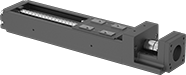
Positioning Slides for Stepper Motors
Add your own stepper motor and controller to precisely move the ball screw and carriage smoothly at high speeds, like a head on an inkjet printer. With a repeatability of ± 0.01 mm—thinner than a strand of hair—the carriage hits the same spot every time. These positioning slides work well for automated assemblies and other applications that require fine, repeatable motion control.
The carriage rides along the inside of the rail, making these slides more compact than traditional carriages and guide rails. Made of steel with a U-shaped rail, these slides resist twisting forces that could affect their positioning. This also means they can be installed with only one end supported or with both ends overhanging. The same load rating applies no matter how the slides are oriented.
Two-axis mounting plates (sold separately) secure two slides together for motion along two axes.
Travel distance per turn, also known as screw lead, is how far the carriage moves with one rotation of the ball screw.
![]() For technical drawings and 3-D models, click on a part number.
For technical drawings and 3-D models, click on a part number.
Dynamic Load Capacity, lbs. | Overall | Carriage | |||||||||||||||
|---|---|---|---|---|---|---|---|---|---|---|---|---|---|---|---|---|---|
| Stroke Lg., mm | Horizontal | Vertical | Max. Speed, mm/s | Travel Distance per Turn, mm | Repeatability, mm | For Shaft Dia. | For Max. Motor Speed, rpm | For Max. Motor Torque, in.-oz. | Lg., mm | Wd., mm | Ht., mm | Lg., mm | Wd., mm | Bearing Type | Base Material | Each | |
For NEMA 14 Motor Frame Size | |||||||||||||||||
| 30 | 148 | 148 | 100 | 1 | ±0.01 | 5mm | 6,000 | 29.3 | 166 | 40 | 42 | 46 | 23 | Ball | Steel | 00000000 | 0000000 |
| 80 | 148 | 148 | 100 | 1 | ±0.01 | 5mm | 6,000 | 29.3 | 216 | 40 | 42 | 46 | 23 | Ball | Steel | 00000000 | 00000000 |
| 110 | 528 | 528 | 200 | 2 | ±0.01 | 5mm | 6,000 | 88.1 | 276 | 50 | 36 | 47.4 | 31 | Ball | Steel | 00000000 | 00000000 |
| 130 | 148 | 148 | 100 | 1 | ±0.01 | 5mm | 6,000 | 29.3 | 266 | 40 | 42 | 46 | 23 | Ball | Steel | 00000000 | 00000000 |
For NEMA 17 Motor Frame Size | |||||||||||||||||
| 100 | 402 | 402 | 470 | 6 | ±0.01 | 5mm | 4,700 | 176 | 277 | 60 | 44.5 | 76 | 37.4 | Ball | Steel | 00000000 | 00000000 |
| 110 | 528 | 528 | 200 | 2 | ±0.01 | 5mm | 6,000 | 88.1 | 276.5 | 50 | 42 | 47.4 | 31 | Ball | Steel | 00000000 | 00000000 |
| 160 | 528 | 528 | 200 | 2 | ±0.01 | 5mm | 6,000 | 88.1 | 326.5 | 50 | 42 | 47.4 | 31 | Ball | Steel | 00000000 | 00000000 |
| 200 | 402 | 402 | 470 | 6 | ±0.01 | 5mm | 4,700 | 176 | 377 | 60 | 44.5 | 76 | 37.4 | Ball | Steel | 00000000 | 00000000 |
| 210 | 528 | 528 | 200 | 2 | ±0.01 | 5mm | 6,000 | 88.1 | 376.5 | 50 | 42 | 47.4 | 31 | Ball | Steel | 00000000 | 00000000 |
For NEMA 23 Motor Frame Size | |||||||||||||||||
| 100 | 402 | 402 | 470 | 6 | ±0.01 | 1/4" | 4,700 | 176 | 280 | 60 | 56.4 | 76 | 37.4 | Ball | Steel | 00000000 | 00000000 |
| 200 | 402 | 402 | 470 | 6 | ±0.01 | 1/4" | 4,700 | 176 | 380 | 60 | 56.4 | 76 | 37.4 | Ball | Steel | 00000000 | 00000000 |
| 300 | 395 | 395 | 790 | 10 | ±0.01 | 1/4" | 6,000 | 176 | 480 | 60 | 56.4 | 76 | 37.4 | Ball | Steel | 00000000 | 00000000 |
| 400 | 395 | 395 | 790 | 10 | ±0.01 | 1/4" | 5,880 | 176 | 580 | 60 | 56.4 | 76 | 37.4 | Ball | Steel | 00000000 | 00000000 |
| 500 | 395 | 395 | 650 | 10 | ±0.01 | 1/4" | 3,900 | 176 | 680 | 60 | 56.4 | 76 | 37.4 | Ball | Steel | 00000000 | 00000000 |
| 600 | 395 | 395 | 470 | 10 | ±0.01 | 1/4" | 2,820 | 176 | 780 | 60 | 56.4 | 76 | 37.4 | Ball | Steel | 00000000 | 00000000 |


Dry-Running Positioning Slides for Stepper Motors

With PTFE sleeve bearings and a low-friction ball screw, these slides don’t require the mess and maintenance of lubrication but still give you precise positioning anywhere along the length of their stroke. Because they have sleeve bearings, they have fewer moving parts, so they perform better in dusty and wet environments than slides with ball bearings. They’re also better at handling impact and vibration.
All slides require a stepper motor, driver, and controller (not included) to operate. As part of this system, they move in precise increments, like the head on an inkjet printer. These positioning slides work well for automated assemblies and other applications that require fine, repeatable motion control.
Travel distance per turn, also known as screw lead, is how far the carriage moves with one rotation of the ball screw.
![]() For technical drawings and 3-D models, click on a part number.
For technical drawings and 3-D models, click on a part number.
Overall | Carriage | ||||||||||||||||
|---|---|---|---|---|---|---|---|---|---|---|---|---|---|---|---|---|---|
| Stroke Lg., mm | Dynamic Horizontal/Vertical Load Capacity, lbs. | Static Load Capacity, lbs. | Max. Speed, mm/s | Travel Distance per Turn, mm | Repeatability, mm | For Shaft Dia. | For Max. Motor Speed, rpm | For Max. Motor Torque, in.-oz. | Lg., mm | Wd., mm | Ht., mm | Lg., mm | Wd., mm | Bearing Type | Base Material | Each | |
For NEMA 17 Motor Frame Size | |||||||||||||||||
| 100 | Not Rated | 630 | 50 | 2 | ±0.1 | 5mm | 1,500 | 71 | 276 | 74 | 56 | 69 | 73 | Sleeve | Aluminum | 0000000 | 0000000 |
| 200 | Not Rated | 630 | 50 | 2 | ±0.1 | 5mm | 1,500 | 71 | 376 | 74 | 56 | 69 | 73 | Sleeve | Aluminum | 0000000 | 000000 |
| 300 | Not Rated | 630 | 50 | 2 | ±0.1 | 5mm | 1,500 | 71 | 476 | 74 | 56 | 69 | 73 | Sleeve | Aluminum | 0000000 | 000000 |
| 400 | Not Rated | 630 | 50 | 2 | ±0.1 | 5mm | 1,500 | 71 | 576 | 74 | 56 | 69 | 73 | Sleeve | Aluminum | 0000000 | 000000 |
| 500 | Not Rated | 630 | 50 | 2 | ±0.1 | 5mm | 1,500 | 71 | 676 | 74 | 56 | 69 | 73 | Sleeve | Aluminum | 0000000 | 000000 |
| 600 | Not Rated | 630 | 50 | 2 | ±0.1 | 5mm | 1,500 | 71 | 776 | 74 | 56 | 69 | 73 | Sleeve | Aluminum | 0000000 | 000000 |
For NEMA 23 Motor Frame Size | |||||||||||||||||
| 100 | Not Rated | 630 | 50 | 2 | ±0.1 | 1/4" | 1,500 | 283 | 277 | 74 | 56 | 69 | 73 | Sleeve | Aluminum | 0000000 | 000000 |
| 200 | Not Rated | 630 | 50 | 2 | ±0.1 | 1/4" | 1,500 | 283 | 377 | 74 | 56 | 69 | 73 | Sleeve | Aluminum | 0000000 | 000000 |
| 300 | Not Rated | 630 | 50 | 2 | ±0.1 | 1/4" | 1,500 | 283 | 477 | 74 | 56 | 69 | 73 | Sleeve | Aluminum | 0000000 | 000000 |
| 400 | Not Rated | 630 | 50 | 2 | ±0.1 | 1/4" | 1,500 | 283 | 577 | 74 | 56 | 69 | 73 | Sleeve | Aluminum | 0000000 | 000000 |
| 500 | Not Rated | 630 | 50 | 2 | ±0.1 | 1/4" | 1,500 | 283 | 677 | 74 | 56 | 69 | 73 | Sleeve | Aluminum | 0000000 | 000000 |
| 600 | Not Rated | 630 | 50 | 2 | ±0.1 | 1/4" | 1,500 | 283 | 777 | 74 | 56 | 69 | 73 | Sleeve | Aluminum | 0000000 | 000000 |