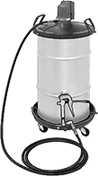
Air-Powered Oil Dispensers
Connect these dispensers to your air system to pressurize the oil in the reservoir and atomize the spray. Dual regulators allow you to adjust the pressure of the oil and the atomized spray. Add a spray valve (sold separately) to direct the flow of oil. A removable filter prevents valve blockage. They have NPTF (Dryseal) threads, which are compatible with NPT threads.

Overall | Air Inlet | Air Outlet | ||||||||||||||
|---|---|---|---|---|---|---|---|---|---|---|---|---|---|---|---|---|
| Cap. | Max. Oil Outlet Pressure, psi | Ht. | Wd. | Dp. | Max. Air Inlet Pressure, psi | Thread Type | Pipe Size | Gender | Thread Type | Pipe Size | Gender | Temp. Range, °F | Mounting Hole Thread Size | For Max. ISO Viscosity Grade | Each | |
1/8 NPTF Female Outlet | ||||||||||||||||
| 2 qt. | 30 | 14 1/4" | 5 13/16" | 5 13/16" | 125 | NPTF | 1/4 | Female | NPTF | 1/8 | Female | -30° to 140° | 5/16"-24 | 150 | 00000000 | 0000000 |
| 1 gal. | 30 | 19 1/4" | 5 13/16" | 5 13/16" | 125 | NPTF | 1/4 | Female | NPTF | 1/8 | Female | -30° to 140° | 5/16"-24 | 150 | 00000000 | 000000 |
| 2 gal. | 30 | 32 1/4" | 5 13/16" | 5 13/16" | 125 | NPTF | 1/4 | Female | NPTF | 1/8 | Female | -30° to 140° | 5/16"-24 | 150 | 00000000 | 00000000 |

| Material | Ht. | OD | ID | Max. Temp., ° F | Each | |
| Rayon | 1 3/8" | 3/4" | 5/8" | 360° | 00000000 | 000000 |
Precision Air-Powered Grease Dispensers


Powered by your air system, these dispensers release a precise amount of grease in timed intervals, so your machine will never have too much or too little. They’ll dispense the right amount even if changing temperatures affect the grease consistency. Back pressure doesn’t impact these dispensers either. But compared to motor-driven dispensers, they’re more complicated to set up. Besides your air system, you’ll need to attach a three-port solenoid valve and either a timer or programmable logic controller (PLC) to control the valve (all not included). If you use a PLC, they’ll prevent over-lubrication when your machine is down by only greasing when it’s running. This is useful for machines with intermittent downtime. Even without a PLC, you can manually cut off the flow without uninstalling the dispenser.
They’re modular, so install or remove pumps as your lubrication needs change. Each pump has mounting holes drilled through their body. Use a screwdriver to turn each pump’s flow-adjustment screw.
These dispensers don’t come with grease, so use the grease that’s best for your machine.
For technical drawings and 3-D models, click on a part number.
Grease Outlet | Overall | Air Inlet | ||||||||||||||
|---|---|---|---|---|---|---|---|---|---|---|---|---|---|---|---|---|
| No. of Grease Outlets | Cap., fl. oz. | Ounces per Cycle, oz. | For NLGI Viscosity Grade | Max. Grease Outlet Pressure, psi | Thread Type | Pipe Size | Gender | Ht. | Wd. | Max. Distance from Lubrication Point, ft. | Loading Method | Thread Type | Pipe Size | Gender | Each | |
| 1 | 1 1/2 | 0-0.007 | 00, 0, 1, 2 | 1,080 | NPT | 1/8 | Female | 8 5/16" | 3 1/4" | 3 | Grease Gun | NPT | 1/8 | Female | 0000000 | 0000000 |
| 2 | 1 1/2 | 0-0.007 | 00, 0, 1, 2 | 1,080 | NPT | 1/8 | Female | 8 5/16" | 4 1/2" | 3 | Grease Gun | NPT | 1/8 | Female | 0000000 | 000000 |
| 4 | 1 1/2 | 0-0.007 | 00, 0, 1, 2 | 1,080 | NPT | 1/8 | Female | 8 5/16" | 7" | 3 | Grease Gun | NPT | 1/8 | Female | 0000000 | 000000 |
| 6 | 1 1/2 | 0-0.007 | 00, 0, 1, 2 | 1,080 | NPT | 1/8 | Female | 8 5/16" | 9 1/2" | 3 | Grease Gun | NPT | 1/8 | Female | 0000000 | 000000 |
| Add-On Dispenser, 1 1/4" Wd. | 0000000 | Each | 0000000 |
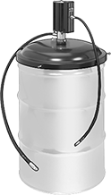
Air-Powered Container-Mount Grease Dispensers


Dispense from your drum or pail of grease using compressed air. Dispensers include a follower plate that moves down the inside of the container as the grease level drops to compress the grease and prevent vapor pockets. Containers not included.
Dispensers deliver grease at the same pressure as your existing grease system, up to the max. grease outlet pressure. Dispensers with a booster gun allow you to increase the pressure to the value listed for max. grease outlet pressure with booster.
Styles A-D have a Z-swivel that connects the outlet hose to the gun and prevents the hose from kinking.
For technical drawings and 3-D models, click on a part number.

Dispensers | ||||||||||||||||
|---|---|---|---|---|---|---|---|---|---|---|---|---|---|---|---|---|
For Container | Air Inlet | Replacement Follower Plates | ||||||||||||||
| Style | Max. Dia. | Max. Ht. | Flow Rate, oz./min. | For NLGI Viscosity Grade | Max. Grease Outlet Pressure, psi | Max. Grease Outlet Pressure with Booster, psi | Grease Outlet Hose Lg., ft. | Material | Max. Pressure, psi | Thread Type | Pipe Size | Gender | Each | Each | ||
With Booster Gun | ||||||||||||||||
| A | 12 3/16" | 12 13/16" | 16 | 00, 0, 1, 2 | 7,500 | 10,000 | 13 | Steel | 150 | NPT | 1/4 | Female | 0000000 | 0000000 | 0000000 | 000000 |
| B | 12" | 16 9/16" | 64 | 00, 0, 1, 2 | 7,500 | 10,000 | 10 | Steel | 150 | NPT | 1/4 | Female | 00000000 | 00000000 | 0000000 | 000000 |
With Standard Gun | ||||||||||||||||
| B | 12" | 16 9/16" | 32 | 00, 0, 1, 2 | 7,500 | __ | 10 | Steel | 150 | NPTF | 1/4 | Female | 0000000 | 00000000 | 0000000 | 000000 |


Dispensers | ||||||||||||||||
|---|---|---|---|---|---|---|---|---|---|---|---|---|---|---|---|---|
For Container | Air Inlet | Replacement Follower Plates | ||||||||||||||
| Style | Max. Dia. | Max. Ht. | Flow Rate, oz./min. | For NLGI Viscosity Grade | Max. Grease Outlet Pressure, psi | Max. Grease Outlet Pressure with Booster, psi | Grease Outlet Hose Lg., ft. | Material | Max. Pressure, psi | Thread Type | Pipe Size | Gender | Each | Each | ||
With Booster Gun | ||||||||||||||||
| A | 15 15/16" | 26" | 16 | 00, 0, 1, 2 | 7,500 | 10,000 | 13 | Steel | 150 | NPT | 1/4 | Female | 0000000 | 000000000 | 0000000 | 0000000 |
| C | 14 7/8" | 27 1/4" | 64 | 00, 0, 1, 2 | 7,500 | 10,000 | 10 | Steel | 150 | NPT | 1/4 | Female | 00000000 | 00000000 | 0000000 | 000000 |
| D | 14 7/8" | 27 1/4" | 64 | 00, 0, 1, 2 | 7,500 | 10,000 | 10 | Steel | 150 | NPT | 1/4 | Female | 00000000 | 00000000 | 0000000 | 000000 |
With Standard Gun | ||||||||||||||||
| C | 14 7/8" | 27 1/4" | 32 | 00, 0, 1, 2 | 7,500 | __ | 10 | Steel | 150 | NPTF | 1/4 | Female | 0000000 | 00000000 | 0000000 | 000000 |
| D | 14 7/8" | 27 1/4" | 32 | 00, 0, 1, 2 | 7,500 | __ | 10 | Steel | 150 | NPTF | 1/4 | Female | 0000000 | 00000000 | 0000000 | 000000 |

For Container | Grease Outlet | Air Inlet | |||||||||||||||
|---|---|---|---|---|---|---|---|---|---|---|---|---|---|---|---|---|---|
| Style | Max. Dia. | Max. Ht. | Flow Rate, oz./min. | For NLGI Viscosity Grade | Max. Grease Outlet Pressure, psi | Hose Lg., ft. | Thread Type | Pipe Size | Gender | Material | Max. Pressure, psi | Hose Lg. ft. | Thread Type | Pipe Size | Gender | Each | |
| E | 23 5/8" | 36 13/16" | 64 | 00, 0, 1, 2 | 7,500 | 4 | NPT | 3/8 | Male | Steel | 150 | 3 | NPT | 1/4 | Female | 00000000 | 000000000 |
Air to Hydraulic Power Converters

Power a hydraulic cylinder from your air system to avoid the setup, cost, and mess of hydraulic fluid. These converters give you more consistent power than using air power for an air cylinder. However, because air works at a lower pressure than hydraulic fluid, your hydraulic cylinder won’t move loads at its full force. Attach these converters to an air line with a speed controller and solenoid (not included).
Note: These converters are not for use near fire.
For technical drawings and 3-D models, click on a part number.
Oil Displacement | O'all | Inlet Connection— BSPT | Outlet Connection— BSPT | Drain Connection— BSPT | Mounting Holes | |||||||||||||
|---|---|---|---|---|---|---|---|---|---|---|---|---|---|---|---|---|---|---|
| Max. Range, mm | Increments, mm | For Max. Hydraulic Cylinder Stroke Lg., mm | Max. Flow Rate, gpm | Max. Pressure, psi | Cap., gal. | Wd., mm | Ht., mm | Pipe Size | Dash Size | Pipe Size | Dash Size | Pipe Size | Dash Size | Number of | Dia., mm | Features | Each | |
40 mm Bore Dia. | ||||||||||||||||||
| 50 | 50 | 60 | 3.3 | 100 | 0.02 | 107 | 213 | 1/4 | 6 | 1/4 | 6 | __ | __ | 4 | 7 | Drain Plug | 0000000 | 000000 |
| 100 | 50 | 120 | 3.3 | 100 | 0.03 | 107 | 263 | 1/4 | 6 | 1/4 | 6 | __ | __ | 4 | 7 | Drain Plug | 0000000 | 00000 |
| 150 | 50 | 180 | 3.3 | 100 | 0.05 | 107 | 313 | 1/4 | 6 | 1/4 | 6 | __ | __ | 4 | 7 | Drain Plug | 0000000 | 00000 |
| 200 | 50 | 250 | 3.3 | 100 | 0.07 | 107 | 363 | 1/4 | 6 | 1/4 | 6 | __ | __ | 4 | 7 | Drain Plug | 0000000 | 00000 |
63 mm Bore Dia. | ||||||||||||||||||
| 50 | 50 | 150 | 7.9 | 100 | 0.04 | 104 | 228 | 3/8 | 6 | 3/4 | 12 | 1/4 | 6 | 4 | 11 | Drain Plug | 0000000 | 00000 |
| 100 | 50 | 300 | 7.9 | 100 | 0.08 | 104 | 278 | 3/8 | 6 | 3/4 | 12 | 1/4 | 6 | 4 | 11 | Drain Plug | 0000000 | 000000 |
| 200 | 50 | 600 | 7.9 | 100 | 0.16 | 104 | 378 | 3/8 | 6 | 3/4 | 12 | 1/4 | 6 | 4 | 11 | Drain Plug | 0000000 | 000000 |
| 300 | 50 | 890 | 7.9 | 100 | 0.24 | 104 | 503 | 3/8 | 6 | 3/4 | 12 | 1/4 | 6 | 4 | 11 | Drain Plug | 0000000 | 000000 |


