


About Heaters for Pipes and Tubes
Self-Regulating Heat Cable—Adjusts its heat output in response to surface as well as surrounding temperatures.
Constant-Wattage Heat Cable—Always puts out the designated amount of watts/ft., regardless of the surrounding temperature.
More
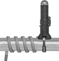
Constant-Wattage Heaters with Adjustable
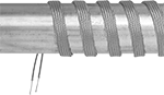
Temperature Control for Pipes and Tubes
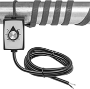
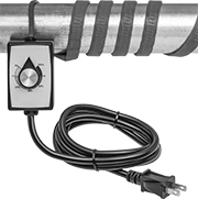
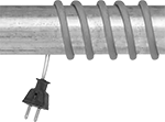
Turn the dial to control the percentage of time that these heaters cycle on, from 5% to 100%. Commonly used to thaw pipes, prevent valves from freezing, and heat beakers and flasks in labs, they're good for temporary and occasional use where rapid heating is required but precise temperature control is not.
Unlike self-regulating heaters, these provide a consistent heat output wattage along the entire length of the cable, regardless of the environmental temperature. They do not have a temperature sensor, so you should only use them in areas where you can monitor them with a thermometer (sold separately). Do not use behind walls, underground, or in other difficult-to-access areas.
With a rubber coating, these heaters are both moisture and chemical resistant. Install them onto surfaces that are free of dirt, grease, and rough edges using fiberglass tape or heat-transfer putty. Do not use electrical tape, duct tape, metal bands, or wire. To prevent burnout, make sure they're in full contact with the surface and have no overlap. To prevent heat loss, wrap with fiberglass insulation.
| Lg., ft. | Wattage, W | Watt Density, W/ft. | Thick. | Environment Temp. Range, °F | Cord Lg., ft. | Cable Cover Material | For Surface Material | For Use Outdoors | Current, A | Each | |
With Wire Leads—240V AC, Single Phase | |||||||||||
|---|---|---|---|---|---|---|---|---|---|---|---|
1/2" Wd. | |||||||||||
| 2 | 72 | 36 | 3/16" | -30° to 450° | 6 | Rubber | Metal | No | 0.3 | 0000000 | 0000000 |
| 4 | 144 | 36 | 3/16" | -30° to 450° | 6 | Rubber | Metal | No | 0.6 | 0000000 | 000000 |
| 6 | 216 | 36 | 3/16" | -30° to 450° | 6 | Rubber | Metal | No | 0.9 | 0000000 | 000000 |
| 8 | 288 | 36 | 3/16" | -30° to 450° | 6 | Rubber | Metal | No | 1.2 | 0000000 | 000000 |
| 10 | 360 | 36 | 3/16" | -30° to 450° | 6 | Rubber | Metal | No | 1.5 | 0000000 | 000000 |
| 12 | 432 | 36 | 3/16" | -30° to 450° | 6 | Rubber | Metal | No | 1.8 | 00000000 | 000000 |
| 20 | 720 | 36 | 3/16" | -30° to 450° | 6 | Rubber | Metal | No | 3 | 00000000 | 000000 |
1" Wd. | |||||||||||
| 2 | 144 | 72 | 3/16" | -30° to 450° | 6 | Rubber | Metal | No | 0.6 | 0000000 | 000000 |
| 4 | 288 | 72 | 3/16" | -30° to 450° | 6 | Rubber | Metal | No | 1.2 | 0000000 | 000000 |
| 6 | 432 | 72 | 3/16" | -30° to 450° | 6 | Rubber | Metal | No | 1.8 | 0000000 | 000000 |
| 8 | 576 | 72 | 3/16" | -30° to 450° | 6 | Rubber | Metal | No | 2.4 | 0000000 | 000000 |
| 10 | 720 | 72 | 3/16" | -30° to 450° | 6 | Rubber | Metal | No | 3 | 0000000 | 000000 |
| 12 | 864 | 72 | 3/16" | -30° to 450° | 6 | Rubber | Metal | No | 3.6 | 00000000 | 000000 |
| 20 | 1,440 | 72 | 3/16" | -30° to 450° | 6 | Rubber | Metal | No | 6 | 0000000 | 000000 |
2" Wd. | |||||||||||
| 10 | 1,440 | 144 | 3/16" | -30° to 450° | 6 | Rubber | Metal | No | 6 | 0000000 | 000000 |
3" Wd. | |||||||||||
| 10 | 1,800 | 180 | 3/16" | -30° to 450° | 6 | Rubber | Metal | No | 7.5 | 0000000 | 000000 |
With Plug—120V AC, Single Phase | |||||||||||
1/2" Wd. | |||||||||||
| 2 | 72 | 36 | 3/16" | -30° to 450° | 6 | Rubber | Metal | No | 0.6 | 0000000 | 000000 |
| 4 | 144 | 36 | 3/16" | -30° to 450° | 6 | Rubber | Metal | No | 1.2 | 0000000 | 000000 |
| 6 | 216 | 36 | 3/16" | -30° to 450° | 6 | Rubber | Metal | No | 1.8 | 0000000 | 000000 |
| 8 | 288 | 36 | 3/16" | -30° to 450° | 6 | Rubber | Metal | No | 2.4 | 0000000 | 000000 |
| 10 | 360 | 36 | 3/16" | -30° to 450° | 6 | Rubber | Metal | No | 3 | 0000000 | 000000 |
| 12 | 432 | 36 | 3/16" | -30° to 450° | 6 | Rubber | Metal | No | 3.6 | 00000000 | 000000 |
| 14 | 504 | 36 | 3/16" | -30° to 450° | 6 | Rubber | Metal | No | 4.2 | 00000000 | 000000 |
| 16 | 576 | 36 | 3/16" | -30° to 450° | 6 | Rubber | Metal | No | 4.8 | 00000000 | 000000 |
| 18 | 648 | 36 | 3/16" | -30° to 450° | 6 | Rubber | Metal | No | 5.4 | 00000000 | 000000 |
| 20 | 720 | 36 | 3/16" | -30° to 450° | 6 | Rubber | Metal | No | 6 | 00000000 | 000000 |
1" Wd. | |||||||||||
| 2 | 144 | 72 | 3/16" | -30° to 450° | 6 | Rubber | Metal | No | 1.2 | 0000000 | 000000 |
| 4 | 288 | 72 | 3/16" | -30° to 450° | 6 | Rubber | Metal | No | 2.4 | 0000000 | 000000 |
| 6 | 432 | 72 | 3/16" | -30° to 450° | 6 | Rubber | Metal | No | 3.6 | 0000000 | 000000 |
| 8 | 576 | 72 | 3/16" | -30° to 450° | 6 | Rubber | Metal | No | 4.8 | 0000000 | 000000 |
| 10 | 720 | 72 | 3/16" | -30° to 450° | 6 | Rubber | Metal | No | 6 | 0000000 | 000000 |
| 12 | 864 | 72 | 3/16" | -30° to 450° | 6 | Rubber | Metal | No | 7.2 | 00000000 | 000000 |
| 14 | 1,008 | 72 | 3/16" | -30° to 450° | 6 | Rubber | Metal | No | 8.4 | 00000000 | 000000 |
| 16 | 1,152 | 72 | 3/16" | -30° to 450° | 6 | Rubber | Metal | No | 9.6 | 00000000 | 000000 |
| 18 | 1,296 | 72 | 3/16" | -30° to 450° | 6 | Rubber | Metal | No | 10.8 | 00000000 | 000000 |
| 20 | 1,440 | 72 | 3/16" | -30° to 450° | 6 | Rubber | Metal | No | 12 | 0000000 | 000000 |
2" Wd. | |||||||||||
| 2 | 288 | 144 | 3/16" | -30° to 450° | 6 | Rubber | Metal | No | 2.4 | 0000000 | 000000 |
| 4 | 576 | 144 | 3/16" | -30° to 450° | 6 | Rubber | Metal | No | 4.8 | 0000000 | 000000 |
| 6 | 864 | 144 | 3/16" | -30° to 450° | 6 | Rubber | Metal | No | 7.2 | 0000000 | 000000 |
| 8 | 1,152 | 144 | 3/16" | -30° to 450° | 6 | Rubber | Metal | No | 9.6 | 0000000 | 000000 |
| 10 | 1,440 | 144 | 3/16" | -30° to 450° | 6 | Rubber | Metal | No | 12 | 0000000 | 000000 |
3" Wd. | |||||||||||
| 2 | 432 | 216 | 3/16" | -30° to 450° | 6 | Rubber | Metal | No | 3.6 | 0000000 | 000000 |
| 4 | 864 | 216 | 3/16" | -30° to 450° | 6 | Rubber | Metal | No | 7.2 | 0000000 | 000000 |
| 6 | 1,296 | 216 | 3/16" | -30° to 450° | 6 | Rubber | Metal | No | 10.8 | 0000000 | 000000 |
| 8 | 1,440 | 180 | 3/16" | -30° to 450° | 6 | Rubber | Metal | No | 12 | 0000000 | 000000 |
| 10 | 1,440 | 144 | 3/16" | -30° to 450° | 6 | Rubber | Metal | No | 12 | 0000000 | 000000 |
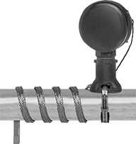
Constant-Wattage Heaters with Temperature Control for Pipes and Tubes
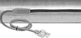
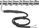
A nonadjustable thermostat turns these heaters on when the temperature drops below 38° F and turns them off when the temperature reaches 45° F. Often used to maintain liquid temperature and viscosity and provide freeze protection in pipe and tube systems, they supply the same wattage regardless of the surrounding temperature and are less prone to power surges than self-regulating heaters. To prevent burnout, they should be installed straight along pipes and tubes; they must not be overlapped or spiraled and must be in full contact with the surface being heated. All are rated for outdoor use. The plastic cable cover provides corrosion resistance and durability. Heaters have a plug with an indicator light that shows when the system has power.
Note: Only install these heaters in accessible locations; do not install them behind walls, underground, or in other difficult-to-access areas. Use fiberglass tape or heat-transfer putty to install them directly on surfaces that are free of dirt, grease, and rough edges. Do not use electrical tape, duct tape, metal bands, or wire. To prevent heat loss and protect heaters from moisture and corrosion, wrap them with fiberglass insulation.
| Lg., ft. | Wattage, W | Watt Density, W/ft. | Current, A | Wd. | Thick. | Environment Temp. Range, °F | For Pipe Dia. | NEMA Style | Cord Lg., ft. | Cable Cover Material | For Surface Material | For Use Outdoors | Each | |
120V AC, Single Phase | ||||||||||||||
|---|---|---|---|---|---|---|---|---|---|---|---|---|---|---|
| 3 | 21 | 7 | 0.2 | 1/2" | 3/8" | -40° to 155° | 3/4" to 1 1/2" | 5-15 | 2 | Plastic | Metal, Plastic | Yes | 0000000 | 000000 |
| 6 | 42 | 7 | 0.4 | 1/2" | 3/8" | -40° to 155° | 3/4" to 1 1/2" | 5-15 | 2 | Plastic | Metal, Plastic | Yes | 0000000 | 00000 |
| 9 | 63 | 7 | 0.5 | 1/2" | 3/8" | -40° to 155° | 3/4" to 1 1/2" | 5-15 | 2 | Plastic | Metal, Plastic | Yes | 0000000 | 00000 |
| 12 | 84 | 7 | 0.7 | 1/2" | 3/8" | -40° to 155° | 3/4" to 1 1/2" | 5-15 | 2 | Plastic | Metal, Plastic | Yes | 0000000 | 00000 |
| 15 | 105 | 7 | 0.9 | 1/2" | 3/8" | -40° to 155° | 3/4" to 1 1/2" | 5-15 | 2 | Plastic | Metal, Plastic | Yes | 0000000 | 00000 |
| 18 | 126 | 7 | 1.1 | 1/2" | 3/8" | -40° to 155° | 3/4" to 1 1/2" | 5-15 | 2 | Plastic | Metal, Plastic | Yes | 0000000 | 00000 |
| 24 | 168 | 7 | 1.4 | 1/2" | 3/8" | -40° to 155° | 3/4" to 1 1/2" | 5-15 | 2 | Plastic | Metal, Plastic | Yes | 0000000 | 00000 |
| 30 | 210 | 7 | 1.8 | 1/2" | 3/8" | -40° to 155° | 3/4" to 1 1/2" | 5-15 | 2 | Plastic | Metal, Plastic | Yes | 0000000 | 00000 |
| 40 | 280 | 7 | 2.3 | 1/2" | 3/8" | -40° to 155° | 3/4" to 1 1/2" | 5-15 | 2 | Plastic | Metal, Plastic | Yes | 0000000 | 00000 |
| 60 | 420 | 7 | 3.5 | 1/2" | 3/8" | -40° to 155° | 3/4" to 1 1/2" | 5-15 | 2 | Plastic | Metal, Plastic | Yes | 0000000 | 00000 |
| 80 | 560 | 7 | 4.7 | 1/2" | 3/8" | -40° to 155° | 3/4" to 1 1/2" | 5-15 | 2 | Plastic | Metal, Plastic | Yes | 0000000 | 00000 |
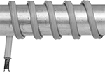
High-Temperature Constant-Wattage Heaters for Pipes and Tubes
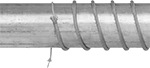
With a maximum heat output of 900° F, these heaters are often used for thawing frozen pipes and rapid spot heating. They supply the same wattage along the entire length of the cable, so they remain consistent regardless of the surrounding temperature. To prevent burnout, heaters must not be overlapped and must be in full contact with the surface being heated.
Heaters with wire leads require a temperature switch or controller for regulating heat output.
Heaters with a plug require a power controller (sold separately).
Note: Only install these heaters in accessible locations; do not install them behind walls, underground, or in other difficult-to-access areas. Use fiberglass tape to install them directly on surfaces that are free of dirt, grease, and rough edges. Do not use electrical tape, duct tape, metal bands, or wire. To prevent heat loss and protect heaters from moisture and corrosion, wrap them with fiberglass insulation.
| Lg. | Wattage, W | Watt Density, W/ft. | Current, A | Cable Cover Material | For Surface Material | For Use Outdoors | Thick. | Environment Temp. Range, °F | Each | |
With Wire Leads | ||||||||||
|---|---|---|---|---|---|---|---|---|---|---|
120V AC, Single Phase | ||||||||||
| 6" | 25 | 50 | 0.2 | Fiberglass | Metal | No | 0.17" | -100° to 900° | 0000000 | 000000 |
| 12" | 50 | 50 | 0.4 | Fiberglass | Metal | No | 0.17" | -100° to 900° | 0000000 | 00000 |
| 24" | 100 | 50 | 0.8 | Fiberglass | Metal | No | 0.17" | -100° to 900° | 0000000 | 00000 |
| 36" | 125 | 41.5 | 1 | Fiberglass | Metal | No | 0.17" | -100° to 900° | 0000000 | 00000 |
| 60" | 250 | 50 | 2.1 | Fiberglass | Metal | No | 0.17" | -100° to 900° | 0000000 | 00000 |
| 96" | 400 | 50 | 3.3 | Fiberglass | Metal | No | 0.17" | -100° to 900° | 0000000 | 00000 |
| 120" | 500 | 50 | 4.2 | Fiberglass | Metal | No | 0.17" | -100° to 900° | 0000000 | 000000 |
With Plug | ||||||||||
120V AC, Single Phase | ||||||||||
| 8" | 35 | 52.5 | 0.3 | Fiberglass | Metal | No | 0.3" | -50° to 900° | 0000000 | 000000 |
| 12" | 50 | 50 | 0.4 | Fiberglass | Metal | No | 0.3" | -50° to 900° | 0000000 | 000000 |
| 24" | 100 | 50 | 0.8 | Fiberglass | Metal | No | 0.3" | -50° to 900° | 0000000 | 000000 |
| 36" | 125 | 41.5 | 1 | Fiberglass | Metal | No | 0.3" | -50° to 900° | 0000000 | 000000 |
| 60" | 250 | 50 | 2.1 | Fiberglass | Metal | No | 0.3" | -50° to 900° | 0000000 | 000000 |
| 96" | 400 | 50 | 3.3 | Fiberglass | Metal | No | 0.3" | -50° to 900° | 0000000 | 000000 |
| 120" | 500 | 50 | 4.2 | Fiberglass | Metal | No | 0.3" | -50° to 900° | 0000000 | 000000 |
| Adjustable-Power Controller for Heaters with Plug | 000000 | Each | 000000 |
Ultra-Flexible Constant-Wattage Heaters for Pipes and Tubes
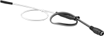
Wrap the flexible heating element around small-diameter pipes and tubes or pack it into tight spaces. These heaters maintain a consistent heat output along the entire length of the cable, regardless of the environmental temperature. All require a temperature switch or controller to regulate heat output. They do not produce an electromagnetic field, so they can be used near electronics.
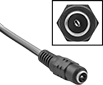
Pair heaters with a 2.1 mm ID barrel connector with an AC adapter (not included) to power them from a standard AC wall outlet.
Note: Only install these heaters in accessible locations; do not install them behind walls, underground, or in other difficult-to-access areas. Use fiberglass tape or heat-transfer putty to install them directly on surfaces that are free of dirt, grease, and rough edges. Do not use electrical tape, duct tape, metal bands, or wire. To prevent heat loss and protect heaters from moisture and corrosion, wrap them with fiberglass insulation.
| Lg., ft. | Wattage, W | Watt Density | Current, A | Wd. | Thick. | Environment Temp. Range, °F | Cable Cover Material | For Surface Material | Each | |
120V AC, Single Phase | ||||||||||
|---|---|---|---|---|---|---|---|---|---|---|
| 2 1/2 | 36 | 2W/sq. in. | 0.3 | 0.5" | 0.06" | -75° to 250° | Silicone Rubber | Ceramic, Glass, Metal, Plastic | 00000000 | 0000000 |
| 4 | 48 | 2W/sq. in. | 0.4 | 0.5" | 0.06" | -75° to 250° | Silicone Rubber | Ceramic, Glass, Metal, Plastic | 00000000 | 000000 |
| 5 1/2 | 72 | 2W/sq. in. | 0.6 | 0.5" | 0.06" | -75° to 250° | Silicone Rubber | Ceramic, Glass, Metal, Plastic | 00000000 | 000000 |
| 8 | 92 | 2W/sq. in. | 0.77 | 0.5" | 0.06" | -75° to 250° | Silicone Rubber | Ceramic, Glass, Metal, Plastic | 00000000 | 000000 |
240V AC, Single Phase | ||||||||||
| 2 1/2 | 36 | 2W/sq. in. | 0.15 | 0.5" | 0.06" | -75° to 250° | Silicone Rubber | Ceramic, Glass, Metal, Plastic | 00000000 | 000000 |
| 4 | 48 | 2W/sq. in. | 0.2 | 0.5" | 0.06" | -75° to 250° | Silicone Rubber | Ceramic, Glass, Metal, Plastic | 00000000 | 000000 |
| 5 1/2 | 72 | 2W/sq. in. | 0.3 | 0.5" | 0.06" | -75° to 250° | Silicone Rubber | Ceramic, Glass, Metal, Plastic | 00000000 | 000000 |
| 8 | 92 | 2W/sq. in. | 0.38 | 0.5" | 0.06" | -75° to 250° | Silicone Rubber | Ceramic, Glass, Metal, Plastic | 00000000 | 000000 |
12V DC | ||||||||||
| 1 | 3 | 3W/ft. | 0.3 | 0.12" | 0.06" | -30° to 220° | Polymer-Based Fiber | Metal, Plastic | 0000000 | 00000 |
| 2 | 6 | 3W/ft. | 0.5 | 0.12" | 0.06" | -30° to 220° | Polymer-Based Fiber | Metal, Plastic | 0000000 | 00000 |
| 3 | 9 | 3W/ft. | 0.8 | 0.12" | 0.06" | -30° to 220° | Polymer-Based Fiber | Metal, Plastic | 0000000 | 00000 |
| 4 | 12 | 3W/ft. | 1 | 0.12" | 0.06" | -30° to 220° | Polymer-Based Fiber | Metal, Plastic | 0000000 | 00000 |
24V DC | ||||||||||
| 2 | 6 | 3W/ft. | 0.3 | 0.12" | 0.06" | -30° to 220° | Polymer-Based Fiber | Metal, Plastic | 0000000 | 00000 |
| 4 | 12 | 3W/ft. | 0.5 | 0.12" | 0.06" | -30° to 220° | Polymer-Based Fiber | Metal, Plastic | 0000000 | 00000 |
| 6 | 18 | 3W/ft. | 0.8 | 0.12" | 0.06" | -30° to 220° | Polymer-Based Fiber | Metal, Plastic | 0000000 | 00000 |
| 8 | 24 | 3W/ft. | 1 | 0.12" | 0.06" | -30° to 220° | Polymer-Based Fiber | Metal, Plastic | 0000000 | 00000 |
36V DC | ||||||||||
| 3 | 9 | 3W/ft. | 0.3 | 0.12" | 0.06" | -30° to 220° | Polymer-Based Fiber | Metal, Plastic | 0000000 | 00000 |
| 6 | 18 | 3W/ft. | 0.5 | 0.12" | 0.06" | -30° to 220° | Polymer-Based Fiber | Metal, Plastic | 0000000 | 00000 |
| 9 | 27 | 3W/ft. | 0.8 | 0.12" | 0.06" | -30° to 220° | Polymer-Based Fiber | Metal, Plastic | 0000000 | 00000 |
| 12 | 36 | 3W/ft. | 1 | 0.12" | 0.06" | -30° to 220° | Polymer-Based Fiber | Metal, Plastic | 0000000 | 000000 |
Heaters | AC Adapters | |||||||||||
|---|---|---|---|---|---|---|---|---|---|---|---|---|
| Lg., ft. | Wattage, W | Watt Density, W/ft. | Current, A | Wd. | Thick. | Environment Temp. Range, °F | Cable Cover Material | For Surface Material | Each | Each | ||
12V DC | ||||||||||||
| 1 | 3 | 3 | 0.3 | 0.12" | 0.06" | -30° to 220° | Polymer-Based Fiber | Metal, Plastic | 0000000 | 000000 | 00000000 | 00000 |
| 2 | 6 | 3 | 0.5 | 0.12" | 0.06" | -30° to 220° | Polymer-Based Fiber | Metal, Plastic | 0000000 | 00000 | 00000000 | 0000 |
| 3 | 9 | 3 | 0.8 | 0.12" | 0.06" | -30° to 220° | Polymer-Based Fiber | Metal, Plastic | 0000000 | 00000 | 00000000 | 00000 |
| 4 | 12 | 3 | 1 | 0.12" | 0.06" | -30° to 220° | Polymer-Based Fiber | Metal, Plastic | 0000000 | 00000 | 00000000 | 00000 |
24V DC | ||||||||||||
| 2 | 6 | 3 | 0.3 | 0.12" | 0.06" | -30° to 220° | Polymer-Based Fiber | Metal, Plastic | 0000000 | 00000 | 00000000 | 00000 |
| 4 | 12 | 3 | 0.5 | 0.12" | 0.06" | -30° to 220° | Polymer-Based Fiber | Metal, Plastic | 0000000 | 00000 | 00000000 | 00000 |
| 6 | 18 | 3 | 0.8 | 0.12" | 0.06" | -30° to 220° | Polymer-Based Fiber | Metal, Plastic | 0000000 | 00000 | 00000000 | 00000 |
| 8 | 24 | 3 | 1 | 0.12" | 0.06" | -30° to 220° | Polymer-Based Fiber | Metal, Plastic | 0000000 | 00000 | 00000000 | 00000 |
Cut-to-Length Constant-Wattage Heaters for Pipes and Tubes
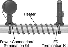
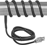
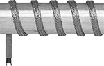
With a cable that supplies the same wattage along the entire length, these heaters remain consistent regardless of the surrounding temperature. All require a temperature switch or controller (sold separately) to regulate heat output. They’re often used to maintain liquid temperature and viscosity and provide freeze protection in pipe and tube systems. To prevent burnout, heaters must not be overlapped and must be in full contact with the surface being heated. All have a plastic cable cover for corrosion resistance and durability. They are FM approved for hazardous locations. A power-connection/termination kit (sold separately) is required.
Power-connection/termination kit (sold separately) includes a junction box and a three-point DIN-mount terminal block to attach to your power source. It also includes adhesive, an end cap, and a power-connection cover to seal off the other end of your cable.
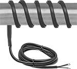
Termination kit (sold separately) includes adhesive, an end cap, and a power-connection cover to seal off the non-powered end of your cable.
LED termination kit (sold separately) has a high-visibility green LED to indicate when the heater is on. It also includes adhesive, an end cap, and a power-connection cover to seal off the non-powered end of your cable.
Note: Only install these heaters in accessible locations; do not install them behind walls, underground, or in other difficult-to-access areas. Use fiberglass tape or heat-transfer putty to install them directly on surfaces that are free of dirt, grease, and rough edges. Do not use electrical tape, duct tape, metal bands, or wire. To prevent heat loss and protect heaters from moisture and corrosion, wrap them with fiberglass insulation.
Per Ft. | ||||||||||||
|---|---|---|---|---|---|---|---|---|---|---|---|---|
| Watt Density, W/ft. | Wd. | Thick. | Max. Lg., ft. | Environment Temp. Range, °F | Wire Connection Type | Cable Cover Material | For Surface Material | Environmental Rating | For Use Outdoors | 1-99 | 100-Up | |
150° F Max. Heat Output | ||||||||||||
120V AC, Single Phase | ||||||||||||
| 2.5 | 1/2" | 11/32" | 500 | -40° to 400° | Wire Leads | Plastic | Metal | NEC Class I Divisions 1, 2 Groups A, B, C, D NEC Class II Divisions 1, 2 Groups E, F, G NEC Class III Divisions 1, 2 | No | 00000000 | 000000 | 000000 |
| 5 | 1/2" | 11/32" | 500 | -40° to 400° | Wire Leads | Plastic | Metal | NEC Class I Divisions 1, 2 Groups A, B, C, D NEC Class II Divisions 1, 2 Groups E, F, G NEC Class III Divisions 1, 2 | No | 00000000 | 00000 | 00000 |
| 8 | 1/2" | 11/32" | 500 | -40° to 400° | Wire Leads | Plastic | Metal | NEC Class I Divisions 1, 2 Groups A, B, C, D NEC Class II Divisions 1, 2 Groups E, F, G NEC Class III Divisions 1, 2 | No | 00000000 | 00000 | 00000 |
| 10 | 1/2" | 11/32" | 500 | -40° to 400° | Wire Leads | Plastic | Metal | NEC Class I Divisions 1, 2 Groups A, B, C, D NEC Class II Divisions 1, 2 Groups E, F, G NEC Class III Divisions 1, 2 | No | 00000000 | 00000 | 00000 |
240V AC, Single Phase | ||||||||||||
| 5 | 1/2" | 11/32" | 500 | -40° to 400° | Wire Leads | Plastic | Metal | NEC Class I Divisions 1, 2 Groups A, B, C, D NEC Class II Divisions 1, 2 Groups E, F, G NEC Class III Divisions 1, 2 | No | 00000000 | 00000 | 00000 |
480V AC, Single Phase | ||||||||||||
| 10 | 1/2" | 11/32" | 500 | -40° to 400° | Wire Leads | Plastic | Metal | NEC Class I Divisions 1, 2 Groups A, B, C, D NEC Class II Divisions 1, 2 Groups E, F, G NEC Class III Divisions 1, 2 | No | 00000000 | 00000 | 00000 |
300° F Max. Heat Output | ||||||||||||
120V AC, Single Phase | ||||||||||||
| 10 | 1/2" | 11/32" | 500 | -60° to 500° | Wire Leads | Plastic | Metal | NEC Class I Divisions 1, 2 Groups A, B, C, D NEC Class II Divisions 1, 2 Groups E, F, G NEC Class III Divisions 1, 2 | No | 00000000 | 00000 | 00000 |
| 15 | 1/2" | 11/32" | 500 | -60° to 500° | Wire Leads | Plastic | Metal | NEC Class I Divisions 1, 2 Groups A, B, C, D NEC Class II Divisions 1, 2 Groups E, F, G NEC Class III Divisions 1, 2 | No | 00000000 | 00000 | 00000 |
240V AC, Single Phase | ||||||||||||
| 10 | 1/2" | 11/32" | 500 | -60° to 500° | Wire Leads | Plastic | Metal | NEC Class I Divisions 1, 2 Groups A, B, C, D NEC Class II Divisions 1, 2 Groups E, F, G NEC Class III Divisions 1, 2 | No | 00000000 | 00000 | 00000 |
| 15 | 1/2" | 11/32" | 500 | -60° to 500° | Wire Leads | Plastic | Metal | NEC Class I Divisions 1, 2 Groups A, B, C, D NEC Class II Divisions 1, 2 Groups E, F, G NEC Class III Divisions 1, 2 | No | 00000000 | 00000 | 00000 |
480V AC, Single Phase | ||||||||||||
| 10 | 1/2" | 11/32" | 500 | -60° to 500° | Wire Leads | Plastic | Metal | NEC Class I Divisions 1, 2 Groups A, B, C, D NEC Class II Divisions 1, 2 Groups E, F, G NEC Class III Divisions 1, 2 NEC Zone 1 Groups IIC, IIB, IIA | No | 00000000 | 00000 | 00000 |
| 15 | 1/2" | 11/32" | 500 | -60° to 500° | Wire Leads | Plastic | Metal | NEC Class I Divisions 1, 2 Groups A, B, C, D NEC Class II Divisions 1, 2 Groups E, F, G NEC Class III Divisions 1, 2 NEC Zone 1 Groups IIC, IIB, IIA | No | 00000000 | 00000 | 00000 |
| 20 | 1/2" | 11/32" | 500 | -60° to 500° | Wire Leads | Plastic | Metal | NEC Class I Divisions 1, 2 Groups A, B, C, D NEC Class II Divisions 1, 2 Groups E, F, G NEC Class III Divisions 1, 2 NEC Zone 1 Groups IIC, IIB, IIA | No | 00000000 | 00000 | 00000 |
Self-Regulating Heaters for Pipes and Tubes
When the ambient temperature changes, these heaters automatically adjust the heat output along the length of their cable. Also known as self-regulating heat cable, they don’t require a separate temperature switch or controller. These heaters use their full wattage for more heat when surrounding temperatures are low and reduce their wattage when temperatures are high. Heat output can simultaneously vary at multiple points along a single cable. They’re often used to maintain liquid temperature and viscosity and provide freeze protection in pipe and tube systems. All are CSA certified for pipe freeze protection and are rated for outdoor use. Heaters can overlap without creating hot spots or risking burnout. A protective rubber cover provides corrosion resistance and durability.
Heaters with a plug are also CSA certified for roof and gutter de-icing applications. The plug has an indicator light that shows when the system has power.
Note: Only install these heaters in accessible locations; do not install them behind walls, underground, or in other difficult-to-access areas. Use fiberglass tape or heat-transfer putty to install them directly on surfaces that are free of dirt, grease, and rough edges. Do not use electrical tape, duct tape, metal bands, or wire. To prevent heat loss and protect heaters from moisture and corrosion, wrap them with fiberglass insulation.
Watt Density, W/ft. | ||||||||||||||
|---|---|---|---|---|---|---|---|---|---|---|---|---|---|---|
| Lg., ft. | Wattage, W | @ 40° F | @ 80° F | @ 100° F | Wd. | Thick. | Environment Temp. Range, °F | Cord Lg., ft. | Cable Cover Material | For Surface Material | For Use Outdoors | Current, A | Each | |
| 6 | 36 | 6 | 3 | 1.5 | 7/16" | 1/4" | -40° to 150° | 6 | Rubber | Metal, Plastic | Yes | 0.15 | 0000000 | 0000000 |
| 12 | 72 | 6 | 3 | 1.5 | 7/16" | 1/4" | -40° to 150° | 6 | Rubber | Metal, Plastic | Yes | 0.3 | 0000000 | 000000 |
| 18 | 108 | 6 | 3 | 1.5 | 7/16" | 1/4" | -40° to 150° | 6 | Rubber | Metal, Plastic | Yes | 0.45 | 0000000 | 000000 |
| 24 | 144 | 6 | 3 | 1.5 | 7/16" | 1/4" | -40° to 150° | 6 | Rubber | Metal, Plastic | Yes | 0.6 | 0000000 | 000000 |
Watt Density, W/ft. | |||||||||||||||
|---|---|---|---|---|---|---|---|---|---|---|---|---|---|---|---|
| Lg., ft. | Wattage, W | @ 40° F | @ 80° F | @ 100° F | Wd. | Thick. | Environment Temp. Range, °F | Cord Lg., ft. | Cable Cover Material | For Surface Material | For Use Outdoors | NEMA Style | Current, A | Each | |
| 6 | 36 | 6 | 3 | 1.5 | 7/16" | 1/4" | -40° to 150° | 6 | Rubber | Metal, Plastic | Yes | 5-15 | 0.3 | 0000000 | 0000000 |
| 12 | 72 | 6 | 3 | 1.5 | 7/16" | 1/4" | -40° to 150° | 6 | Rubber | Metal, Plastic | Yes | 5-15 | 0.6 | 0000000 | 000000 |
| 18 | 108 | 6 | 3 | 1.5 | 7/16" | 1/4" | -40° to 150° | 6 | Rubber | Metal, Plastic | Yes | 5-15 | 0.9 | 0000000 | 000000 |
| 24 | 144 | 6 | 3 | 1.5 | 7/16" | 1/4" | -40° to 150° | 6 | Rubber | Metal, Plastic | Yes | 5-15 | 1.2 | 0000000 | 000000 |
| 50 | 300 | 6 | 3 | 1.5 | 7/16" | 1/4" | -40° to 150° | 6 | Rubber | Metal, Plastic | Yes | 5-15 | 2.5 | 0000000 | 000000 |
| 75 | 450 | 6 | 3 | 1.5 | 7/16" | 1/4" | -40° to 150° | 6 | Rubber | Metal, Plastic | Yes | 5-15 | 3.75 | 0000000 | 000000 |
| 100 | 600 | 6 | 3 | 1.5 | 7/16" | 1/4" | -40° to 150° | 6 | Rubber | Metal, Plastic | Yes | 5-15 | 5 | 0000000 | 000000 |
Cut-to-Length Self-Regulating Heaters for Pipes and Tubes
Also known as self-regulating heat cable, these heaters automatically adjust heat output at different points along their length to account for differences in environmental temperature. They output their full wattage where temperature is low and heat is needed. Where it’s warmer, they output reduced wattage. They’re often used to maintain liquid temperature and viscosity and provide freeze protection in pipe and tube systems. Heaters can be overlapped without creating hot spots or risking burnout. All require a power connection/termination kit (sold separately).
Heaters with a plastic cable cover are rated for use in hazardous locations. They are also more corrosion resistant and durable than heaters without a cable cover.
Power-connection/termination kits include a junction box and a three-point DIN-mount terminal block for attaching your power source. They also include adhesive, an end cap, and a power-connection cover to seal off the other end of your cable.
Termination kits include adhesive, an end cap, and a power-connection cover to seal off the non-powered end of your cable.
LED termination kits have a high-visibility green LED to indicate when the heater is on. They also include adhesive, an end cap, and a power-connection cover to seal off the non-powered end of your cable.
Splice kits let you connect two heating cables. They include adhesive, splice-connection covers, and wire-splicing connectors.
T-splice kits let you create a tee connection between heating cables. They include adhesive, splice-connection covers, and wire-splicing connectors.
Note: Only install these heaters in accessible locations; do not install them behind walls, underground, or in other difficult-to-access areas. Use fiberglass tape or heat-transfer putty to install them directly on surfaces that are free of dirt, grease, and rough edges. Do not use electrical tape, duct tape, metal bands, or wire. To prevent heat loss and protect heaters from moisture and corrosion, wrap them with fiberglass insulation.
Watt Density, W/ft. | Per Ft. | ||||||||||||
|---|---|---|---|---|---|---|---|---|---|---|---|---|---|
| @ 50° F | @ 100° F | @ 150° F | Wd. | Thick. | Max. Lg., ft. | Environment Temp. Range, °F | Wire Connection Type | For Surface Material | Environmental Rating | For Use Outdoors | 1-99 | 100-Up | |
Without Cable Cover | |||||||||||||
| 3 | 1 | 0.5 | 1/2" | 3/16" | 500 | -60° to 185° | Wire Leads | Metal, Plastic | __ | No | 0000000 | 00000 | 00000 |
| 5 | 2.5 | 1 | 1/2" | 3/16" | 500 | -60° to 185° | Wire Leads | Metal, Plastic | __ | No | 0000000 | 0000 | 0000 |
| 8 | 4.5 | 1.7 | 1/2" | 3/16" | 500 | -60° to 185° | Wire Leads | Metal, Plastic | __ | No | 0000000 | 0000 | 0000 |
| 10 | 5.5 | 2 | 1/2" | 3/16" | 500 | -60° to 185° | Wire Leads | Metal, Plastic | __ | No | 0000000 | 00000 | 0000 |
With Plastic Cable Cover | |||||||||||||
| 3 | 1.5 | 0.2 | 9/16" | 1/4" | 500 | -60° to 185° | Wire Leads | Metal, Plastic | NEC Class I Divisions 1, 2 Groups A, B, C, D NEC Class II Divisions 1, 2 Groups E, F, G NEC Class III Divisions 1, 2 | No | 0000000 | 00000 | 0000 |
| 5 | 2.5 | 1 | 9/16" | 1/4" | 500 | -60° to 185° | Wire Leads | Metal, Plastic | NEC Class I Divisions 1, 2 Groups A, B, C, D NEC Class II Divisions 1, 2 Groups E, F, G NEC Class III Divisions 1, 2 | No | 0000000 | 00000 | 0000 |
| 8 | 4.5 | 1.8 | 9/16" | 1/4" | 500 | -60° to 185° | Wire Leads | Metal, Plastic | NEC Class I Divisions 1, 2 Groups A, B, C, D NEC Class II Divisions 1, 2 Groups E, F, G NEC Class III Divisions 1, 2 | No | 0000000 | 00000 | 0000 |
| 10 | 5.7 | 2.1 | 9/16" | 1/4" | 500 | -60° to 185° | Wire Leads | Metal, Plastic | NEC Class I Divisions 1, 2 Groups A, B, C, D NEC Class II Divisions 1, 2 Groups E, F, G NEC Class III Divisions 1, 2 | No | 0000000 | 00000 | 0000 |
Watt Density, W/ft. | Per Ft. | ||||||||||||
|---|---|---|---|---|---|---|---|---|---|---|---|---|---|
| @ 50° F | @ 100° F | @ 150° F | Wd. | Thick. | Max. Lg., ft. | Environment Temp. Range, °F | Wire Connection Type | For Surface Material | Environmental Rating | For Use Outdoors | 1-99 | 100-Up | |
Without Cable Cover | |||||||||||||
| 3 | 1 | 0.5 | 1/2" | 3/16" | 500 | -60° to 185° | Wire Leads | Metal, Plastic | __ | No | 0000000 | 00000 | 00000 |
| 5 | 2.5 | 1 | 1/2" | 3/16" | 500 | -60° to 185° | Wire Leads | Metal, Plastic | __ | No | 0000000 | 0000 | 0000 |
| 8 | 4.5 | 1.7 | 1/2" | 3/16" | 500 | -60° to 185° | Wire Leads | Metal, Plastic | __ | No | 0000000 | 0000 | 0000 |
| 10 | 5.5 | 2 | 1/2" | 3/16" | 500 | -60° to 185° | Wire Leads | Metal, Plastic | __ | No | 0000000 | 00000 | 0000 |
With Plastic Cable Cover | |||||||||||||
| 8 | 4.5 | 1.8 | 9/16" | 1/4" | 500 | -60° to 185° | Wire Leads | Metal, Plastic | NEC Class I Divisions 1, 2 Groups A, B, C, D NEC Class II Divisions 1, 2 Groups E, F, G NEC Class III Divisions 1, 2 | No | 0000000 | 00000 | 0000 |
| 10 | 5.7 | 2.1 | 9/16" | 1/4" | 500 | -60° to 185° | Wire Leads | Metal, Plastic | NEC Class I Divisions 1, 2 Groups A, B, C, D NEC Class II Divisions 1, 2 Groups E, F, G NEC Class III Divisions 1, 2 | No | 0000000 | 00000 | 0000 |
Watt Density, W/ft. | Per Ft. | ||||||||||||
|---|---|---|---|---|---|---|---|---|---|---|---|---|---|
| @ 50° F | @ 150° F | @ 250° F | Wd. | Thick. | Max. Lg., ft. | Environment Temp. Range, °F | Wire Connection Type | For Surface Material | Environmental Rating | For Use Outdoors | 1-99 | 100-Up | |
With Plastic Cable Cover | |||||||||||||
| 9 | 6 | 3 | 7/16" | 1/4" | 500 | -75° to 400° | Wire Leads | Metal, Plastic | NEC Class I Divisions 1, 2 Groups A, B, C, D NEC Class II Divisions 1, 2 Groups E, F, G NEC Class III Divisions 1, 2 NEC Zone 1 Groups IIC, IIB, IIA NEC Zone 21 Groups IIIC, IIIB, IIIA | No | 00000000 | 000000 | 000000 |
| 12 | 8.5 | 5 | 7/16" | 1/4" | 500 | -75° to 400° | Wire Leads | Metal, Plastic | NEC Class I Divisions 1, 2 Groups A, B, C, D NEC Class II Divisions 1, 2 Groups E, F, G NEC Class III Divisions 1, 2 NEC Zone 1 Groups IIC, IIB, IIA NEC Zone 21 Groups IIIC, IIIB, IIIA | No | 00000000 | 00000 | 00000 |
| 15 | 11 | 7 | 7/16" | 1/4" | 500 | -75° to 400° | Wire Leads | Metal, Plastic | NEC Class I Divisions 1, 2 Groups A, B, C, D NEC Class II Divisions 1, 2 Groups E, F, G NEC Class III Divisions 1, 2 NEC Zone 1 Groups IIC, IIB, IIA NEC Zone 21 Groups IIIC, IIIB, IIIA | No | 00000000 | 00000 | 00000 |
| 20 | 15 | 10.5 | 7/16" | 1/4" | 500 | -75° to 400° | Wire Leads | Metal, Plastic | NEC Class I Divisions 1, 2 Groups A, B, C, D NEC Class II Divisions 1, 2 Groups E, F, G NEC Class III Divisions 1, 2 NEC Zone 1 Groups IIC, IIB, IIA NEC Zone 21 Groups IIIC, IIIB, IIIA | No | 00000000 | 00000 | 00000 |
Watt Density, W/ft. | Per Ft. | ||||||||||||
|---|---|---|---|---|---|---|---|---|---|---|---|---|---|
| @ 50° F | @ 150° F | @ 250° F | Wd. | Thick. | Max. Lg., ft. | Environment Temp. Range, °F | Wire Connection Type | For Surface Material | Environmental Rating | For Use Outdoors | 1-99 | 100-Up | |
With Plastic Cable Cover | |||||||||||||
| 12 | 8.5 | 5 | 7/16" | 1/4" | 500 | -75° to 400° | Wire Leads | Metal, Plastic | NEC Class I Divisions 1, 2 Groups A, B, C, D NEC Class II Divisions 1, 2 Groups E, F, G NEC Class III Divisions 1, 2 NEC Zone 1 Groups IIC, IIB, IIA NEC Zone 21 Groups IIIC, IIIB, IIIA | No | 00000000 | 000000 | 000000 |
| 20 | 15 | 10.5 | 7/16" | 1/4" | 500 | -75° to 400° | Wire Leads | Metal, Plastic | NEC Class I Divisions 1, 2 Groups A, B, C, D NEC Class II Divisions 1, 2 Groups E, F, G NEC Class III Divisions 1, 2 NEC Zone 1 Groups IIC, IIB, IIA NEC Zone 21 Groups IIIC, IIIB, IIIA | No | 00000000 | 00000 | 00000 |
Ultra-High Temperature Constant-Wattage Heaters for Pipes and Tubes
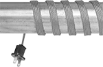
For demanding applications such as hot-melt transfer pipes, these heaters have a maximum heat output of 1400° F. The wattage and heat output stay consistent along the entire length of the cable, regardless of the temperature of the environment. All require a temperature switch or controller (sold separately) for regulating heat output. To prevent burnout, heaters must not overlap and must be in full contact with the surface being heated.
Heaters with a plug require a power controller (sold separately).
Note: Only install these heaters in accessible locations; do not install them behind walls, underground, or in other difficult-to-access areas. Use fiberglass tape or heat-transfer putty to install them directly on surfaces that are free of dirt, grease, and rough edges. Do not use electrical tape, duct tape, metal bands, or wire. To prevent heat loss and protect heaters from moisture and corrosion, wrap them with fiberglass insulation.
| Lg., ft. | Wattage, W | Watt Density, W/ft. | Current, A | Wd. | Thick. | Environment Temp. Range, °F | Cable Cover Material | For Surface Material | For Use Outdoors | Each | |
With Wire Leads | |||||||||||
|---|---|---|---|---|---|---|---|---|---|---|---|
120V AC, Single Phase | |||||||||||
| 2 | 39 | 19.5 | 0.3 | 1/2" | 1/8" | -60° to 1400° | Fiberglass | Ceramic, Glass, Metal | No | 00000000 | 000000 |
| 2 | 104 | 52 | 0.9 | 1/2" | 1/8" | -60° to 1400° | Fiberglass | Ceramic, Glass, Metal | No | 00000000 | 00000 |
| 2 | 156 | 78 | 1.3 | 1/2" | 1/8" | -60° to 1400° | Fiberglass | Ceramic, Glass, Metal | No | 00000000 | 00000 |
| 4 | 78 | 19.5 | 0.7 | 1/2" | 1/8" | -60° to 1400° | Fiberglass | Ceramic, Glass, Metal | No | 00000000 | 00000 |
| 4 | 208 | 52 | 1.7 | 1/2" | 1/8" | -60° to 1400° | Fiberglass | Ceramic, Glass, Metal | No | 00000000 | 00000 |
| 4 | 312 | 78 | 2.6 | 1/2" | 1/8" | -60° to 1400° | Fiberglass | Ceramic, Glass, Metal | No | 00000000 | 00000 |
| 6 | 117 | 19.5 | 1 | 1/2" | 1/8" | -60° to 1400° | Fiberglass | Ceramic, Glass, Metal | No | 00000000 | 00000 |
| 6 | 312 | 52 | 2.6 | 1/2" | 1/8" | -60° to 1400° | Fiberglass | Ceramic, Glass, Metal | No | 00000000 | 00000 |
| 6 | 468 | 78 | 3.9 | 1/2" | 1/8" | -60° to 1400° | Fiberglass | Ceramic, Glass, Metal | No | 00000000 | 00000 |
| 8 | 156 | 19.5 | 1.3 | 1/2" | 1/8" | -60° to 1400° | Fiberglass | Ceramic, Glass, Metal | No | 00000000 | 000000 |
| 8 | 416 | 52 | 3.5 | 1/2" | 1/8" | -60° to 1400° | Fiberglass | Ceramic, Glass, Metal | No | 00000000 | 000000 |
| 8 | 624 | 78 | 5.2 | 1/2" | 1/8" | -60° to 1400° | Fiberglass | Ceramic, Glass, Metal | No | 00000000 | 000000 |
| 10 | 195 | 19.5 | 1.6 | 1/2" | 1/8" | -60° to 1400° | Fiberglass | Ceramic, Glass, Metal | No | 00000000 | 000000 |
| 10 | 520 | 52 | 4.3 | 1/2" | 1/8" | -60° to 1400° | Fiberglass | Ceramic, Glass, Metal | No | 00000000 | 000000 |
| 12 | 234 | 19.5 | 2 | 1/2" | 1/8" | -60° to 1400° | Fiberglass | Ceramic, Glass, Metal | No | 00000000 | 000000 |
| 16 | 312 | 19.5 | 2.6 | 1/2" | 1/8" | -60° to 1400° | Fiberglass | Ceramic, Glass, Metal | No | 00000000 | 000000 |
240V AC, Single Phase | |||||||||||
| 2 | 39 | 19.5 | 0.2 | 1/2" | 1/8" | -60° to 1400° | Fiberglass | Ceramic, Glass, Metal | No | 00000000 | 00000 |
| 2 | 104 | 52 | 0.4 | 1/2" | 1/8" | -60° to 1400° | Fiberglass | Ceramic, Glass, Metal | No | 00000000 | 00000 |
| 2 | 156 | 78 | 0.7 | 1/2" | 1/8" | -60° to 1400° | Fiberglass | Ceramic, Glass, Metal | No | 00000000 | 00000 |
| 4 | 78 | 19.5 | 0.3 | 1/2" | 1/8" | -60° to 1400° | Fiberglass | Ceramic, Glass, Metal | No | 00000000 | 00000 |
| 4 | 208 | 52 | 0.9 | 1/2" | 1/8" | -60° to 1400° | Fiberglass | Ceramic, Glass, Metal | No | 00000000 | 00000 |
| 4 | 312 | 78 | 1.3 | 1/2" | 1/8" | -60° to 1400° | Fiberglass | Ceramic, Glass, Metal | No | 00000000 | 00000 |
| 6 | 117 | 19.5 | 0.5 | 1/2" | 1/8" | -60° to 1400° | Fiberglass | Ceramic, Glass, Metal | No | 00000000 | 00000 |
| 6 | 312 | 52 | 1.3 | 1/2" | 1/8" | -60° to 1400° | Fiberglass | Ceramic, Glass, Metal | No | 00000000 | 00000 |
| 6 | 468 | 78 | 2 | 1/2" | 1/8" | -60° to 1400° | Fiberglass | Ceramic, Glass, Metal | No | 00000000 | 00000 |
| 8 | 156 | 19.5 | 0.7 | 1/2" | 1/8" | -60° to 1400° | Fiberglass | Ceramic, Glass, Metal | No | 00000000 | 000000 |
| 8 | 416 | 52 | 1.7 | 1/2" | 1/8" | -60° to 1400° | Fiberglass | Ceramic, Glass, Metal | No | 00000000 | 000000 |
| 8 | 624 | 78 | 2.6 | 1/2" | 1/8" | -60° to 1400° | Fiberglass | Ceramic, Glass, Metal | No | 00000000 | 000000 |
| 10 | 195 | 19.5 | 0.8 | 1/2" | 1/8" | -60° to 1400° | Fiberglass | Ceramic, Glass, Metal | No | 00000000 | 000000 |
| 10 | 520 | 52 | 2.2 | 1/2" | 1/8" | -60° to 1400° | Fiberglass | Ceramic, Glass, Metal | No | 00000000 | 000000 |
| 12 | 234 | 19.5 | 1 | 1/2" | 1/8" | -60° to 1400° | Fiberglass | Ceramic, Glass, Metal | No | 00000000 | 000000 |
| 16 | 312 | 19.5 | 1.3 | 1/2" | 1/8" | -60° to 1400° | Fiberglass | Ceramic, Glass, Metal | No | 00000000 | 000000 |
With Plug | |||||||||||
120V AC, Single Phase | |||||||||||
| 2 | 39 | 19.5 | 0.3 | 1/2" | 1/8" | -60° to 1400° | Fiberglass | Ceramic, Glass, Metal | No | 00000000 | 00000 |
| 2 | 104 | 52 | 0.9 | 1/2" | 1/8" | -60° to 1400° | Fiberglass | Ceramic, Glass, Metal | No | 00000000 | 00000 |
| 2 | 156 | 78 | 1.3 | 1/2" | 1/8" | -60° to 1400° | Fiberglass | Ceramic, Glass, Metal | No | 00000000 | 00000 |
| 4 | 78 | 19.5 | 0.7 | 1/2" | 1/8" | -60° to 1400° | Fiberglass | Ceramic, Glass, Metal | No | 00000000 | 00000 |
| 4 | 208 | 52 | 1.7 | 1/2" | 1/8" | -60° to 1400° | Fiberglass | Ceramic, Glass, Metal | No | 00000000 | 00000 |
| 4 | 312 | 78 | 2.6 | 1/2" | 1/8" | -60° to 1400° | Fiberglass | Ceramic, Glass, Metal | No | 00000000 | 00000 |
| 6 | 117 | 19.5 | 1 | 1/2" | 1/8" | -60° to 1400° | Fiberglass | Ceramic, Glass, Metal | No | 00000000 | 00000 |
| 6 | 312 | 52 | 2.6 | 1/2" | 1/8" | -60° to 1400° | Fiberglass | Ceramic, Glass, Metal | No | 00000000 | 00000 |
| 6 | 468 | 78 | 3.9 | 1/2" | 1/8" | -60° to 1400° | Fiberglass | Ceramic, Glass, Metal | No | 00000000 | 00000 |
| 8 | 156 | 19.5 | 1.3 | 1/2" | 1/8" | -60° to 1400° | Fiberglass | Ceramic, Glass, Metal | No | 00000000 | 000000 |
| 8 | 416 | 52 | 3.5 | 1/2" | 1/8" | -60° to 1400° | Fiberglass | Ceramic, Glass, Metal | No | 00000000 | 000000 |
| 8 | 624 | 78 | 5.2 | 1/2" | 1/8" | -60° to 1400° | Fiberglass | Ceramic, Glass, Metal | No | 00000000 | 000000 |
| 10 | 195 | 19.5 | 1.6 | 1/2" | 1/8" | -60° to 1400° | Fiberglass | Ceramic, Glass, Metal | No | 00000000 | 000000 |
| 10 | 520 | 52 | 4.3 | 1/2" | 1/8" | -60° to 1400° | Fiberglass | Ceramic, Glass, Metal | No | 00000000 | 000000 |
| 12 | 234 | 19.5 | 2 | 1/2" | 1/8" | -60° to 1400° | Fiberglass | Ceramic, Glass, Metal | No | 00000000 | 000000 |
| 16 | 312 | 19.5 | 2.6 | 1/2" | 1/8" | -60° to 1400° | Fiberglass | Ceramic, Glass, Metal | No | 00000000 | 000000 |
| Adjustable-Power Controller for Heaters with Plug | 000000 | Each | 000000 |