


Hazardous Location Relays

Sealed for safety, these relays are a good choice for hazardous locations where combustible or corrosive gases may be present.
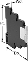
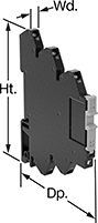
Relays with screw terminals or spring-clamp terminals are considered interface relays, so they’re placed between your controller and components to isolate the input and output circuits. This means they protect your component from voltage spikes while amplifying the relay’s signal and reducing interference for reliable transmission. They are often used for switching applications, such as small motors and pilot lights. The included relay socket mounts on 35 mm DIN rail (also known as DIN 3 rail). Relays with spring-clamp terminals connect and disconnect to wires without needing to turn screws. With no screws to shake loose with vibration, the terminals hold tight over time.
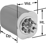
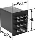
Relays with circular-pin terminals or quick-disconnect terminals are hermetically sealed—completely air- and watertight—to shield internal parts from gases, moisture, and other contaminants. They plug into relay sockets (sold separately) for easy installation.
Relay sockets mount to 35 mm DIN rail (also known as DIN 3 rail) or flat surfaces.
![]() For technical drawings and 3-D models, click on a part number.
For technical drawings and 3-D models, click on a part number.
Relays | Relay Sockets | |||||||||||||
|---|---|---|---|---|---|---|---|---|---|---|---|---|---|---|
| Number of Terminals | Input Voltage | Control Current, mA | Switching Current @ Voltage | Max. Switching Voltage | hp @ Switching Voltage | Ht. | Wd. | Dp. | Quick-Disconnect Tab Wd. | Environmental Rating | Each | Each | ||
Screw Terminals | ||||||||||||||
1 Circuit Controlled with 1 Off (Normally Open) or 1 On (Normally Closed)—SPDT | ||||||||||||||
| 5 | 12V AC, 12V DC | 15.5 | 6 A @ 240 V AC/30 V DC | 400V AC/125V DC | __ | 2.9" | 0.2" | 3.5" | __ | IP20; NEC Class I Division 2 Groups A, B, C, D | 00000000 | 000000 | 000000 | 00 |
| 5 | 12V AC, 12V DC | 29 | 12 A @ 240 V AC/24 V DC | 400V AC/300V DC | __ | 2.9" | 0.6" | 3.5" | __ | IP20; NEC Class I Division 2 Groups A, B, C, D | 00000000 | 00000 | 000000 | 00 |
| 5 | 24V AC, 24V DC | 13.5 | 6 A @ 240 V AC/30 V DC | 400V AC/125V DC | __ | 3.5" | 0.2" | 2.9" | __ | IP20; NEC Class I Division 2 Groups A, B, C, D | 0000000 | 00000 | 000000 | 00 |
| 5 | 24V AC, 24V DC | 13.5 | 16 A @ 240 V AC/24 V DC | 400V AC/300V DC | __ | 3.5" | 0.6" | 2.9" | __ | IP20; NEC Class I Division 2 Groups A, B, C, D | 0000000 | 00000 | 000000 | 00 |
| 5 | 48V AC, 48V DC | 4 | 6 A @ 240 V AC/30 V DC | 400V AC/125V DC | __ | 3.5" | 0.2" | 2.9" | __ | IP20; NEC Class I Division 2 Groups A, B, C, D | 0000000 | 00000 | 000000 | 00 |
| 5 | 48V AC, 48V DC | 4 | 16 A @ 240 V AC/24 V DC | 400V AC/300V DC | __ | 3.5" | 0.6" | 2.9" | __ | IP20; NEC Class I Division 2 Groups A, B, C, D | 0000000 | 00000 | 000000 | 00 |
| 5 | 120V AC, 120V DC | 3.5 | 6 A @ 240 V AC/30 V DC | 400V AC/125V DC | __ | 3.5" | 0.2" | 2.9" | __ | IP20; NEC Class I Division 2 Groups A, B, C, D | 0000000 | 00000 | 000000 | 00 |
| 5 | 120V AC, 120V DC | 3.5 | 16 A @ 240 V AC/24 V DC | 400V AC/300V DC | __ | 3.5" | 0.6" | 2.9" | __ | IP20; NEC Class I Division 2 Groups A, B, C, D | 0000000 | 00000 | 000000 | 00 |
| 5 | 240V AC, 240V DC | 3.5 | 6 A @ 240 V AC/30 V DC | 400V AC/125V DC | __ | 3.5" | 0.2" | 2.9" | __ | IP20; NEC Class I Division 2 Groups A, B, C, D | 0000000 | 00000 | 000000 | 00 |
| 5 | 240V AC, 240V DC | 3.5 | 16 A @ 240 V AC/24 V DC | 400V AC/300V DC | __ | 3.5" | 0.6" | 2.9" | __ | IP20; NEC Class I Division 2 Groups A, B, C, D | 0000000 | 00000 | 000000 | 00 |
2 Circuits Controlled with 2 Off (Normally Open) or 2 On (Normally Closed)—DPDT | ||||||||||||||
| 8 | 24V AC, 24V DC | 13.5 | 8 A @ 240 V AC/24 V DC | 400V AC/300V DC | __ | 3.5" | 0.6" | 2.9" | __ | IP20; NEC Class I Division 2 Groups A, B, C, D | 0000000 | 00000 | 000000 | 00 |
| 8 | 48V AC, 48V DC | 4 | 8 A @ 240 V AC/24 V DC | 400V AC/300V DC | __ | 3.5" | 0.6" | 2.9" | __ | IP20; NEC Class I Division 2 Groups A, B, C, D | 0000000 | 00000 | 000000 | 00 |
| 8 | 120V AC, 120V DC | 3.5 | 8 A @ 240 V AC/24 V DC | 400V AC/300V DC | __ | 3.5" | 0.6" | 2.9" | __ | IP20; NEC Class I Division 2 Groups A, B, C, D | 0000000 | 00000 | 000000 | 00 |
| 8 | 240V AC, 240V DC | 3.5 | 8 A @ 240 V AC/24 V DC | 400V AC/300V DC | __ | 3.5" | 0.6" | 2.9" | __ | IP20; NEC Class I Division 2 Groups A, B, C, D | 0000000 | 00000 | 000000 | 00 |
Spring-Clamp Terminals | ||||||||||||||
1 Circuit Controlled with 1 Off (Normally Open) or 1 On (Normally Closed)—SPDT | ||||||||||||||
| 5 | 12V AC, 12V DC | 15.5 | 6 A @ 240 V AC/30 V DC | 400V AC/125V DC | __ | 2.9" | 0.2" | 3.7" | __ | IP20; NEC Class I Division 2 Groups A, B, C, D | 0000000 | 00000 | 000000 | 00 |
| 5 | 12V AC, 12V DC | 29 | 12 A @ 240 V AC/24 V DC | 400V AC/300V DC | __ | 2.9" | 0.6" | 3.7" | __ | IP20; NEC Class I Division 2 Groups A, B, C, D | 0000000 | 00000 | 000000 | 00 |
| 5 | 24V AC, 24V DC | 13.5 | 6 A @ 240 V AC/30 V DC | 400V AC/125V DC | __ | 2.9" | 0.2" | 3.7" | __ | IP20; NEC Class I Division 2 Groups A, B, C, D | 0000000 | 00000 | 000000 | 00 |
| 5 | 24V AC, 24V DC | 20 | 12 A @ 240 V AC/24 V DC | 400V AC/300V DC | __ | 2.9" | 0.6" | 3.7" | __ | IP20; NEC Class I Division 2 Groups A, B, C, D | 0000000 | 00000 | 000000 | 00 |
| 5 | 120V AC, 120V DC | 3.5 | 6 A @ 240 V AC/30 V DC | 400V AC/125V DC | __ | 2.9" | 0.2" | 3.7" | __ | IP20; NEC Class I Division 2 Groups A, B, C, D | 0000000 | 00000 | 000000 | 00 |
| 5 | 120V AC, 120V DC | 4 | 12 A @ 240 V AC/24 V DC | 400V AC/300V DC | __ | 2.9" | 0.6" | 3.7" | __ | IP20; NEC Class I Division 2 Groups A, B, C, D | 0000000 | 00000 | 000000 | 00 |
Circular-Pin Terminals—Hermetically Sealed | ||||||||||||||
2 Circuits Controlled with 2 Off (Normally Open) or 2 On (Normally Closed)—DPDT | ||||||||||||||
| 8 | 120V AC | 10 | 12 A @ 120 V AC/24 V DC | 300V AC | 1/3 hp @ 120 V AC | 1.6" | 1.4" | 2.1" | __ | NEC Class I Division 2 Groups A, B, C, D | 0000000 | 000000 | 0000000 | 00000 |
| 8 | 24V DC | 38 | 12 A @ 120 V AC/24 V DC | 300V AC | 1/3 hp @ 120 V AC | 1.6" | 1.4" | 2.1" | __ | NEC Class I Division 2 Groups A, B, C, D | 0000000 | 000000 | 0000000 | 0000 |
3 Circuits Controlled with 3 Off (Normally Open) or 3 On (Normally Closed)—3PDT | ||||||||||||||
| 11 | 120V AC | 100 | 12 A @ 120 V AC/240 V AC | 300V AC | 1/3 hp @ 120 V AC | 1.6" | 1.4" | 2.1" | __ | NEC Class I Division 2 Groups A, B, C, D | 00000000 | 000000 | 0000000 | 00000 |
Quick-Disconnect Terminals—Hermetically Sealed | ||||||||||||||
4 Circuits Controlled with 4 Off (Normally Open) or 4 On (Normally Closed)—4PDT | ||||||||||||||
| 14 | 120V AC | 100 | 3 A @ 120 V AC/240 V AC | 240V AC | 1/10 hp @ 120 V AC | 1.2" | 0.9" | 1.3" | 0.125" | NEC Class I Division 2 Groups A, B, C, D | 0000000 | 000000 | 0000000 | 00000 |
Expansion Modules for Programmable Logic Controllers
No need to program multiple PLCs—these modules expand your automated system, keeping everything conjoined and configured on one processor. Use them when you’re out of space on your DIN rail or need additional input/output functions.
These modules meet NEC safety standards, so they can be used in hazardous locations. They’re also rated IP20 to protect your fingers from touching live wires. Modules are UL and C-UL listed, CE marked, and CSA certified, meeting strict domestic and international safety requirements.
Control modules connect directly to the main PLC rack. Insert them in between the processor and the first input/output module.
Interface modules attach to a separate expansion rack, which requires its own power supply (not included). The interface comes with an end plate, which caps off each rack and ends communication with the processor. A maximum of three expansion racks can be hooked up from the main PLC rack.
Use the expansion cords (sold separately) to connect the control and interface modules together. Cords are also IP20 rated, UL and C-UL listed, CE marked, and CSA certified. Total cord length for your entire system should not exceed 39 ft.
![]() For technical drawings and 3-D models, click on a part number.
For technical drawings and 3-D models, click on a part number.


