


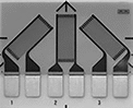
Compression Force Sensors for Tight Spaces
Thinner than a credit card, these force sensors fit into narrow spaces to measure the applied load between two surfaces. While they’re less accurate than larger alternatives such as load cells and handheld force gauges, these will fit almost anywhere. Place them within an industrial press to make sure it’s operating in a safe range, or form them to the contour of a forklift seat to test the concept of adding a smart switch that detects when an operator is sitting and ready to operate the forklift. Sensors should be calibrated before first use. Also known as force sensing resistors.
![]() For technical drawings and 3-D models, click on a part number.
For technical drawings and 3-D models, click on a part number.
 Kit with USB-A Connection |  Kit with Wi-Fi Connection | Tab Connection | 2-Pin Connection |
3-Pin Connection |
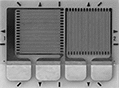
Kits come with software to analyze data from sensors. Kits with USB-A connection include a hub that plugs into your computer’s USB port. Kits with Wi-Fi connection use a hub that wirelessly connects to a computer or tablet within a sensing distance of 210 feet. The hub’s transmitter is certified 802.11b radio – 802.11b/g/n to meet IEEE standards for compatibility with other devices.
Additional sensors and hubs (both sold separately) expand the connections kits.
To connect 3-pin and 2-pin sensors into hubs with USB connections, adapters (sold separately) are required.
Sensor | Hub | ||||||||||||||
|---|---|---|---|---|---|---|---|---|---|---|---|---|---|---|---|
| PC Connection Type | Sensor Connection Type | No. of Sensors Included | Capacity, English | Capacity, Newtons | Lg., mm | Wd., mm | Sensing Area Dia., mm | Sensing Distance, ft. | Battery Life, hrs. | No. of Batteries Included | Cord Lg., ft. | For Max. No. of Sensors | For Operating System | Each | |
| USB-A | Tab | 3 | 1 lbs. 25 lbs. 150 lbs. | 4.4 N 111 N 667 N | 229 | 14 | 9.53 | __ | __ | __ | 10 | 16 | Windows Vista Windows 7 Windows 8 Windows 8.1 Windows 10 Windows 11 | 0000000 | 000000000 |
| Wi-Fi | 3 Pin, 2 Pin | 3 | 1 lbs. 25 lbs. 150 lbs. | 4.4 N 111 N 667 N | 197 | 14 | 9.53 | 0-210 | 5 | 3 | __ | 16 | Windows 2000 Windows XP Windows Vista Windows 7 Windows 8 Windows 8.1 Windows 10 Windows 11 | 0000000 | 00000000 |


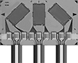
Expand your connection kit with additional sensors. Using more than one sensor allows you to monitor pressure at multiple points across a machine. Each sensor requires its own hub. Track changes in resistance by adding a multimeter, or use the data recording software included in our kits (sold separately).
Sensors | ||||||||||||||||
|---|---|---|---|---|---|---|---|---|---|---|---|---|---|---|---|---|
Capacity | Measuring Increments | Extension Cables | ||||||||||||||
| English | Newtons | Accuracy | English | Newtons | Wd., mm | Thick., mm | Sensing Area Dia., mm | Sensing Area Lg., mm | Max. Current, mA | Input Voltage Range | Temp. Range, °F | Choose a Lg., mm | Each | Each | ||
Round—Tab Connection | ||||||||||||||||
| 1 lbs. | 4 N | ±3% | 0.1 lbs. | 0.01 N | 14 | 0.203 | 9.53 | __ | 2.5 | 0.25-1.25V DC | -40° to 140° | 229 | 0000000 | 000000 | 000000 | 00 |
| 25 lbs. | 111 N | ±3% | 0.1 lbs. | 0.01 N | 14 | 0.203 | 9.53 | __ | 2.5 | 0.25-1.25V DC | -40° to 140° | 229 | 0000000 | 00000 | 000000 | 00 |
| 150 lbs. | 667 N | ±3% | 0.1 lbs. | 0.01 N | 14 | 0.203 | 9.53 | __ | 2.5 | 0.25-1.25V DC | -40° to 140° | 229 | 0000000 | 00000 | 000000 | 00 |
Round—3-Pin Connection | ||||||||||||||||
| 1 lbs. | 4 N | ±3% | 0.1 lbs. | 0.01 N | 14 | 0.203 | 9.53 | __ | 2.5 | 0.25-1.25V DC | -40° to 140° | 000000 | 00000 | 0000000 | 000000 | |
| 25 lbs. | 111 N | ±3% | 0.1 lbs. | 0.01 N | 14 | 0.203 | 9.53 | __ | 2.5 | 0.25-1.25V DC | -40° to 140° | 000000 | 00000 | 0000000 | 00000 | |
| 50 lbs. | 222 N | ±3% | 0.1 lbs. | 0.01 N | 14 | 0.203 | 9.53 | __ | 2.5 | 0.25-1.25V DC | -40° to 400° | 000000 | 00000 | 0000000 | 00000 | |
| 100 lbs. | 445 N | ±3% | 0.1 lbs. | 0.01 N | 14 | 0.203 | 9.53 | __ | 2.5 | 0.25-1.25V DC | -40° to 140° | 000000 | 00000 | 0000000 | 00000 | |
| 150 lbs. | 667 N | ±3% | 0.1 lbs. | 0.01 N | 14 | 0.203 | 9.53 | __ | 2.5 | 0.25-1.25V DC | -40° to 140° | 191 | 0000000 | 00000 | 0000000 | 00000 |
Round—2-Pin Connection | ||||||||||||||||
| 1 lbs. | 4 N | ±3% | 0.1 lbs. | 0.01 N | 14 | 0.203 | 9.53 | __ | 2.5 | 0.25-1.25V DC | -40° to 185° | 25 | 0000000 | 00000 | 0000000 | 00000 |
| 4 lbs. | 18 N | ±3% | 0.1 lbs. | 0.01 N | 7.6 | 0.203 | 3.8 | __ | 2.5 | 0.25-1.25V DC | -40° to 140° | 16 | 0000000 | 00000 | 000000 | 00 |
| 25 lbs. | 111 N | ±3% | 0.1 lbs. | 0.01 N | 14 | 0.203 | 9.53 | __ | 2.5 | 0.25-1.25V DC | -40° to 140° | 25 | 0000000 | 00000 | 0000000 | 00000 |
| 25 lbs. | 111 N | ±3% | 0.1 lbs. | 0.01 N | 31.8 | 0.203 | 25.4 | __ | 2.5 | 0.25-1.25V DC | -40° to 140° | 25 | 0000000 | 00000 | 0000000 | 00000 |
| 100 lbs. | 445 N | ±3% | 0.1 lbs. | 0.01 N | 14 | 0.203 | 9.53 | __ | 2.5 | 0.25-1.25V DC | -40° to 140° | 25 | 0000000 | 00000 | 0000000 | 00000 |
Square—2-Pin Connection | ||||||||||||||||
| 50 lbs. | 222 N | ±3% | 0.1 lbs. | 0.01 N | 55.9 | 0.203 | __ | 50.8 | 2.5 | 0.25-1.25V DC | -40° to 140° | 81 | 0000000 | 00000 | 0000000 | 00000 |


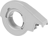
Use hubs to expand your connection kit. Each sensor requires its own hub. Track changes in resistance by adding a multimeter, or use the data recording software included in our kits (sold separately).

Adapters are required to connect 3-pin and 2-pin sensors into hubs with a USB connection.
Sensor Connection Type | |||
|---|---|---|---|
| Input | Output | Each | |
| 3-Pin and 2-Pin Female | Tab Male | 0000000 | 000000 |

Use male pin connectors to create a new male end on a trimmed sensor. Install a female end onto a sensor or another component with female pin connectors.
Strain Gauges
Measure strain across one or multiple directions by gluing or welding these strain gauges onto a structure. They’re often used in structural testing and monitoring applications to measure the deformation or displacement of material caused by force.
Weld-on strain gauges are best for places where glue might not set or where high temperatures prevent the use of adhesives.
Solder wire leads onto strain gauges with solder terminals after the strain gauge has bonded to your surface. After soldering, apply a protective coating.
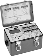
Optional indicators record changes in force, doing the combined job of a multimeter, signal conditioner, and bridge amplifier. They’re battery-operated and portable. Using the included software, operate and configure them straight from your PC. These indicators have no internal memory, but they include an SD card to store your readings. Connect them to strain gauges using wire leads. If installing them in dirty or wet environments, just close the lid after attaching the lead wires.
Installation tape holds the strain gauge in place while you install it and minimizes the risk of contaminating your surface.
Surface cleaners help remove contaminants introduced during mounting. Phosphoric acid cleaners, also known as conditioners, accelerate the surface cleaning process. Ammonia cleaners neutralize any chemicals that have been introduced, helping your gauge mount properly.
Protective coatings extend the life of your strain gage by protecting it from moisture and dust.
![]() For technical drawings and 3-D models, click on a part number.
For technical drawings and 3-D models, click on a part number.
Grid | Overall | |||||||||
|---|---|---|---|---|---|---|---|---|---|---|
| Resistance, ohms | Accuracy | Lg. | Wd. | Lg. | Wd. | Material | Temperature Range, °F | Pkg. Qty. | Pkg. | |
Linear Grid Pattern | ||||||||||
For Use With Cast Iron, Composites, Printed Circuit Board, Steel | ||||||||||
| 350 | ±0.2% | 0.125" | 0.1" | 0.275" | 0.12" | C70600 Copper Nickel | -100° to 350° | 5 | 0000000 | 000000 |
| 350 | ±0.2% | 0.25" | 0.12" | 0.415" | 0.12" | C70600 Copper Nickel | -100° to 350° | 5 | 00000000 | 00000 |
| 350 | ±0.3% | 0.062" | 0.12" | 0.22" | 0.12" | C70600 Copper Nickel | -100° to 350° | 5 | 00000000 | 000000 |
Multi-Direction Grid Pattern | ||||||||||
For Use With Cast Iron, Composites, Printed Circuit Board, Steel | ||||||||||
| 350 | ±0.2% | 0.25" | 0.12" | 0.5" | 0.76" | C70600 Copper Nickel | -100° to 350° | 5 | 00000000 | 000000 |
| 350 | ±0.4% | 0.062" | 0.062" | 0.222" | 0.42" | C70600 Copper Nickel | -100° to 350° | 5 | 00000000 | 000000 |
| 350 | ±0.4% | 0.125" | 0.06" | 0.3" | 0.56" | C70600 Copper Nickel | -100° to 350° | 5 | 00000000 | 000000 |
Tee Grid Pattern | ||||||||||
For Use With Cast Iron, Composites, Printed Circuit Board, Steel | ||||||||||
| 350 | ±0.4% | 0.062" | 0.08" | 0.205" | 0.225" | C70600 Copper Nickel | -100° to 350° | 5 | 00000000 | 000000 |
| 350 | ±0.4% | 0.125" | 0.165" | 0.325" | 0.365" | C70600 Copper Nickel | -100° to 350° | 5 | 00000000 | 000000 |
| 350 | ±0.4% | 0.25" | 0.29" | 0.45" | 0.65" | C70600 Copper Nickel | -100° to 350° | 5 | 00000000 | 000000 |
Grid | Overall | |||||||||
|---|---|---|---|---|---|---|---|---|---|---|
| Resistance, ohms | Accuracy | Lg. | Wd. | Lg. | Wd. | Material | Temperature Range, °F | Pkg. Qty. | Pkg. | |
Linear Grid Pattern | ||||||||||
For Use With Cast Iron, Composites, Printed Circuit Board, Steel | ||||||||||
| 350 | ±0.4% | 0.23" | 0.125" | 0.63" | 0.34" | C70600 Copper Nickel | -60° to 180° | 5 | 00000000 | 0000000 |
Grid | Overall | ||||||||||
|---|---|---|---|---|---|---|---|---|---|---|---|
| Resistance, ohms | Accuracy | Lg. | Wd. | Lg. | Wd. | Wire Lead Lg., ft. | Material | Temperature Range, °F | Pkg. Qty. | Pkg. | |
Linear Grid Pattern | |||||||||||
For Use With Aluminum, Brass, Tin | |||||||||||
| 120 | ±0.3% | 0.235" | 0.1" | 0.301" | 0.1" | 3 | C70600 Copper Nickel | -60° to 180° | 10 | 0000000 | 0000000 |
| 350 | ±0.3% | 0.06" | 0.1" | 0.166" | 0.13" | 3 | C70600 Copper Nickel | -60° to 180° | 10 | 0000000 | 000000 |
| 350 | ±0.3% | 0.235" | 0.1" | 0.301" | 0.1" | 3 | C70600 Copper Nickel | -60° to 180° | 10 | 0000000 | 000000 |
For Use With Cast Iron, Composites, Printed Circuit Board, Steel | |||||||||||
| 120 | ±0.3% | 0.06" | 0.1" | 0.166" | 0.13" | 3 | C70600 Copper Nickel | -60° to 180° | 10 | 0000000 | 000000 |
| 120 | ±0.3% | 0.125" | 0.1" | 0.205" | 0.1" | 3 | C70600 Copper Nickel | -60° to 180° | 10 | 0000000 | 000000 |
| 120 | ±0.3% | 0.235" | 0.1" | 0.301" | 0.1" | 3 | C70600 Copper Nickel | -60° to 180° | 10 | 0000000 | 000000 |
| 350 | ±0.3% | 0.06" | 0.1" | 0.166" | 0.13" | 3 | C70600 Copper Nickel | -60° to 180° | 10 | 0000000 | 000000 |
| 350 | ±0.3% | 0.125" | 0.1" | 0.205" | 0.1" | 3 | C70600 Copper Nickel | -60° to 180° | 10 | 0000000 | 000000 |
For Use With Composites, Nickel Iron, Titanium Silicate | |||||||||||
| 350 | ±0.3% | 0.235" | 0.1" | 0.301" | 0.1" | 3 | C70600 Copper Nickel | -60° to 180° | 10 | 0000000 | 000000 |
Grid | Overall | ||||||||||
|---|---|---|---|---|---|---|---|---|---|---|---|
| Resistance, ohms | Accuracy | Lg. | Wd. | Lg. | Wd. | Wire Lead Lg., ft. | Material | Temperature Range, °F | Pkg. Qty. | Pkg. | |
Linear Grid Pattern | |||||||||||
For Use With Aluminum, Brass, Tin | |||||||||||
| 350 | ±0.2% | 0.03" | 0.063" | 0.095" | 0.063" | 3 | Nickel Chromium | -100° to 400° | 1 | 0000000 | 000000 |
For Use With Cast Iron, Composites, Printed Circuit Board, Steel | |||||||||||
| 120 | ±0.3% | 0.015" | 0.02" | 0.052" | 0.042" | 9 | Nickel Chromium | -60° to 180° | 1 | 00000000 | 000000 |
| 350 | ±0.2% | 0.03" | 0.063" | 0.095" | 0.063" | 9 | Nickel Chromium | -100° to 400° | 1 | 0000000 | 00000 |
| 350 | ±0.3% | 0.06" | 0.1" | 0.166" | 0.13" | 9 | C70600 Copper Nickel | -60° to 180° | 10 | 0000000 | 000000 |
| 350 | ±0.3% | 0.125" | 0.1" | 0.233" | 0.13" | 9 | C70600 Copper Nickel | -60° to 180° | 10 | 0000000 | 000000 |
| 350 | ±0.3% | 0.235" | 0.1" | 0.343" | 0.13" | 9 | C70600 Copper Nickel | -60° to 180° | 10 | 0000000 | 000000 |
For Use With Composites, Nickel Iron, Titanium Silicate | |||||||||||
| 350 | ±0.3% | 0.235" | 0.1" | 0.301" | 0.1" | 9 | C70600 Copper Nickel | -60° to 180° | 10 | 0000000 | 000000 |
Grid | Overall | ||||||||||
|---|---|---|---|---|---|---|---|---|---|---|---|
| Resistance, ohms | Accuracy | Lg. | Wd. | Lg. | Wd. | Wire Lead Lg., ft. | Material | Temperature Range, °F | Pkg. Qty. | Pkg. | |
Multi-Direction Grid Pattern | |||||||||||
For Use With Cast Iron, Composites, Printed Circuit Board, Steel | |||||||||||
| 350 | ±0.3% | 0.125" | 0.079" | 0.231" | 0.429" | 9 | C70600 Copper Nickel | -60° to 180° | 5 | 00000000 | 0000000 |
| 350 | ±0.5% | 0.014" | 0.012" | 0.071" | 0.143" | 9 | Nickel Chromium | -100° to 400° | 1 | 00000000 | 00000 |
No. of | |||||||||||||||||
|---|---|---|---|---|---|---|---|---|---|---|---|---|---|---|---|---|---|
| Inputs | Terminals per Input | Resistance, ohms | Accuracy | Sampling Interval | Response Time | Display Type | Lg. | Wd. | Ht. | Weight, lbs. | For Wire Gauge | Batteries Included | Software Included | Temperature Range, °F | Includes | Each | |
| 4 | 10 | 120, 350, 1,000 | ±0.1% | 1 sec - 1 hr. | 1 sec. | LCD | 9" | 6" | 6" | 4.4 | 28-16 | Yes | Yes | 32° to 120° | 32 GB SD Card, 6-ft. Lg. USB Cord | 00000000 | 000000000 |
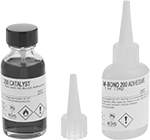
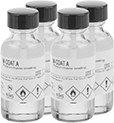
Container | |||||||||
|---|---|---|---|---|---|---|---|---|---|
| Size, fl. oz. | Type | Begins to Harden | Reaches Full Strength | Consistency (Viscosity) | Temperature Range, °F | For Use On | Includes | Each | |
| 1 | Bottle | 1 min. | 5 min. | Thin Liquid (130 cP) | -25° to 150° | Aluminum, Composites, Glass, Steel | Catalyst | 0000000 | 0000000 |
| Width | Length, ft. | Color | Temperature Range | Features | Each | |
| 3/4" | 216 | Clear | 400° F | Tape Dispenser | 0000000 | 0000000 |
Dry Time | |||||
|---|---|---|---|---|---|
| Container Size, fl. oz. | Touch, min. | Overall, hrs. | Pkg. Qty. | Pkg. | |
| 1 | 20 | 2 | 4 | 0000000 | 000000 |