


Filter by
System of Measurement
Maximum Flow
Fitting Connection


Body Material
Flow Measurement Unit
Maximum Temperature
Connects To
Maximum Pressure @ Temperature
Mounting Position


Minimum Temperature
DFARS Specialty Metals
Export Control Classification Number (ECCN)
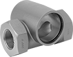
Socket-Connect Flowmeter/Totalizers with Remote Display
Sensors
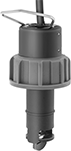 |
Sensors thread onto the tee fitting.
Tee Fittings
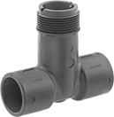 |
Tee fittings mount inline with your pipe. They have two unthreaded socket ends that bond to unthreaded PVC pipe with PVC cement and primer.
Temp., ° F | |||||||||||
|---|---|---|---|---|---|---|---|---|---|---|---|
Inlet/Outlet Connection | Sensor Connection | Pipe Schedule | Flow, gpm | Max. Pressure @ Temp. | Min. | Max. | Mounting Position | Each | |||
PVC Body | |||||||||||
| 1/2 Socket Connect Female Inlet Pipe × 1/2 Socket Connect Female Outlet Pipe | 1 1/4 NPSM Threaded Male Pipe | 80 | 1 to 18.9 | 180 psi @ 70° F | 33 | 149 | Any Angle | 4114K231 | 0000000 | ||
| 3/4 Socket Connect Female Inlet Pipe × 3/4 Socket Connect Female Outlet Pipe | 1 1/4 NPSM Threaded Male Pipe | 80 | 1.7 to 33.2 | 180 psi @ 70° F | 33 | 149 | Any Angle | 4114K232 | 000000 | ||
| 1 Socket Connect Female Inlet Pipe × 1 Socket Connect Female Outlet Pipe | 1 1/4 NPSM Threaded Male Pipe | 80 | 2.7 to 53.9 | 180 psi @ 70° F | 33 | 149 | Any Angle | 4114K233 | 000000 | ||
| 1 1/2 Socket Connect Female Inlet Pipe × 1 1/2 Socket Connect Female Outlet Pipe | 1 1/4 NPSM Threaded Male Pipe | 80 | 6.4 to 126.9 | 180 psi @ 70° F | 33 | 149 | Any Angle | 4114K235 | 000000 | ||
| 2 Socket Connect Female Inlet Pipe × 2 Socket Connect Female Outlet Pipe | 1 1/4 NPSM Threaded Male Pipe | 80 | 10.5 to 209.2 | 180 psi @ 70° F | 33 | 149 | Any Angle | 4114K236 | 000000 | ||
| 3 Socket Connect Female Inlet Pipe × 3 Socket Connect Female Outlet Pipe | 1 1/4 NPSM Threaded Male Pipe | 80 | 23 to 460.8 | 180 psi @ 70° F | 33 | 149 | Any Angle | 4114K238 | 000000 | ||
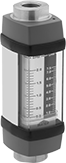
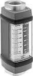
Insertion Flowmeters
 |
No need to disassemble your PVC pipeline—insert these flowmeters into a drilled hole and secure them using the included clamps. As liquid flows through the meter, it pushes an indicator up the scale, showing you the flow rate. They have a clear body, so you can check the color and clarity of flowing liquid to identify and diagnose problems. Mount these flowmeters vertically.
These flowmeters are calibrated with water but can be used with other liquids. If you’re using these with a liquid other than water, you’ll need to calculate the flow rate by multiplying the number shown on the scale by the specific-gravity conversion factor for your liquid.
Flow for Pipe Schedule, gpm | Temp., ° F | ||||||||||||
|---|---|---|---|---|---|---|---|---|---|---|---|---|---|
Pipe Size | Schedule 40 | Schedule 80 | Overall Ht. | Accuracy | Max. Pressure @ Temp. | Min. | Max. | Seal Material | Mounting Position | Each | |||
Acrylic Plastic Body with 316 Stainless Steel Fittings | |||||||||||||
| 1 1/4 | 9 to 50 | 8 to 40 | 6" | ±5% | 75 psi @ 70° F | 33 | 190 | Neoprene | Vertical | 4349K2 | 0000000 | ||
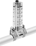
High-Temperature and Pressure Flowmeters
 |
With a maximum temperature of 240° F and a maximum pressure of 3,500 psi, these flowmeters measure the flow rate of liquids that are too hot or pressurized for standard flowmeters. As your liquid flows through, it pushes an indicator up the scale, showing you the flow rate. They measure flow correctly in any mounting orientation. Install them inline with your pipe system. They have brass fittings that resist impact better than plastic fittings.
These flowmeters are calibrated with water but can be used with other liquids. If you’re using these with a liquid other than water, you’ll need to calculate the flow rate by multiplying the number shown on the scale by the specific-gravity conversion factor for your liquid.
Temp., ° F | |||||||||||
|---|---|---|---|---|---|---|---|---|---|---|---|
Flow, gpm | End-to-End Lg. | Accuracy | Max. Pressure @ Temp. | Min. | Max. | Seal Material | Mounting Position | Each | |||
Brass Body with Brass Fittings | |||||||||||
1 1/4 NPTF Female | |||||||||||
| 5 to 50 | 12 1/4" | ±2% | 3,500 psi @ 70° F | -20 | 240 | Fluoroelastomer | Any Angle | 4230K78 | 000000000 | ||
| 10 to 100 | 12 1/4" | ±2% | 3,500 psi @ 70° F | -20 | 240 | Fluoroelastomer | Any Angle | 4230K88 | 00000000 | ||
| 10 to 150 | 12 1/4" | ±2% | 3,500 psi @ 70° F | -20 | 240 | Fluoroelastomer | Any Angle | 4230K29 | 00000000 | ||
Totalizers for Natural, Propane, and Butane Gas
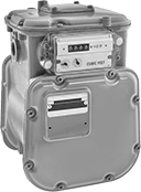 | 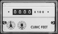 |
Analog Display |
Often used in heating, cooking, and power-generating systems, these totalizers measure the total amount of natural gas, propane, and butane that flow through them. They use positive displacement, so they measure the flow by passing specific volumes of gas through their diaphragm. Their total cannot be reset. Mount them inline with your pipe system.
Temp., ° F | ||||||||||||||||
|---|---|---|---|---|---|---|---|---|---|---|---|---|---|---|---|---|
Connections | Flow, ft³/hr | Maximum Total Volume Displayed | Accuracy | Max. Pressure @ Temp. | Min. | Max. | Seal Material | Mounting Position | Ht. | Wd. | Dp. | Display Type | Each | |||
Aluminum Body with Iron Fittings | ||||||||||||||||
| 1 1/4 NPT Male | 0 to 425 | 999,900 Cubic Feet | ±1% | 10 psi @ 70° F | -30 | 140 | Buna-N | Horizontal | 15" | 11" | 10" | Analog | 4360K22 | 0000000 | ||
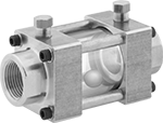
Flow- and Pressure-Testing Flowmeters for Oil
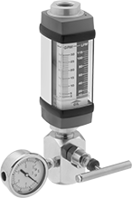 |
Often used to find worn components or leaks, these flowmeters have a valve, so you can test the flow of oil from pumps and other equipment at different pressures. Keep the valve fully open to measure the maximum flow rate at zero pressure. Pressure increases as you close the valve. As oil flows through, it pushes an indicator up the scale, showing you the flow rate. The scale rotates 360°, so you can check the flow rate from any angle. These flowmeters are accurate in any mounting orientation. Mount them inline with your pipe system.
These flowmeters are calibrated with oil but can be used with other liquids. If you’re using these with a liquid other than oil, you’ll need to calculate the flow rate by multiplying the number shown on the scale by the specific-gravity conversion factor for your liquid.
Temp., ° F | Pressure Gauge | ||||||||||||||
|---|---|---|---|---|---|---|---|---|---|---|---|---|---|---|---|
Flow, gpm | End-to-End Lg. | Accuracy | Max. Pressure @ Temp. | Min. | Max. | Measurement, psi | Dial Size | Body Material | Seal Material | Mounting Position | Features | Each | |||
Aluminum Fitting with Aluminum Valve | |||||||||||||||
1 1/4 NPTF Threaded Male Pipe Inlet × 1 1/4 NPTF Threaded Female Pipe Outlet | |||||||||||||||
| 10 to 100 | 22" | ±2% | 3,500 psi @ 70° F | -20 | 240 | 0 to 3,500 | 2 1/2" | Aluminum | Fluoroelastomer | Any Angle | Rotating Scale | 4263K62 | 000000000 | ||
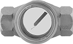
Flow Sights with Indicator for Water and Oil
 |  |
Rotor Indicator Front Window | Rotor Indicator Front and Back Window |
The indicator moves when flow is present, so it’s easy to visually confirm flow from a distance.
Rotor Indicator—Rotor indicator is the most obvious indicator of flow for maximum visibility.
Bronze Body—Sights with a bronze body are harder and more durable than sights with a brass body for a longer service life.
316 Stainless Steel Body—Sights with a 316 stainless steel body are more corrosion resistant than sights with a brass or bronze body.
Front and Back Window—Back window can be backlit to increase the visibility of dark liquids.
Window | Indicator | |||||||||||||||
|---|---|---|---|---|---|---|---|---|---|---|---|---|---|---|---|---|
Pipe Size | Thread Type | Gender | Temp. Range, ° F | Dia. | Type | End-to-End Lg. | Ht. | Max. Pressure @ Temp. | Direction of Flow | Material | Color | For Use With | Each | |||
Rotor Indicator | ||||||||||||||||
Bronze Body | ||||||||||||||||
| 1 1/4 | NPT | Female | -20 to 200 | 2" | Front | 4 3/8" | 3 1/8" | 125 psi @ 70° F | Left to Right, Right to Left | Acetal | White | Water, Oil | 4195K18 | 0000000 | ||
| 1 1/4 | NPT | Female | -20 to 200 | 2" | Front and Back | 4 3/8" | 3 1/8" | 125 psi @ 70° F | Left to Right, Right to Left | Acetal | White | Water, Oil | 4200K35 | 000000 | ||
316 Stainless Steel Body | ||||||||||||||||
| 1 1/4 | NPT | Female | 40 to 200 | 2" | Front and Back | 4 3/8" | 2 1/2" | 125 psi @ 70° F | Left to Right, Right to Left | 316 Stainless Steel | — | Water, Oil | 5088K58 | 000000 | ||
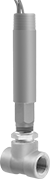
High-Temperature and Pressure Flowmeters for Oil
 |
If the oil in your line is too hot or pressurized for standard flowmeters, use these flowmeters to measure the flow rate. As oil flows through, it pushes an indicator up the scale, showing you the flow rate. The scale rotates 360°, so you can check the flow rate from any angle. These flowmeters measure flow correctly in any mounting orientation. Install them inline with your pipe system.
These flowmeters are calibrated with oil but can be used with other liquids. If you’re using these with a liquid other than oil, you’ll need to calculate the flow rate by multiplying the number shown on the scale by the specific-gravity conversion factor for your liquid.
Choose a fitting material that is compatible with the oil you're running through your line.
Pipe Size | Flow, gpm | End-to-End Lg. | Accuracy | Max. Pressure @ Temp. | Min. Temp., ° F | Body Material | Seal Material | Mounting Position | Features | Each | |||
|---|---|---|---|---|---|---|---|---|---|---|---|---|---|
NPTF Female Pipe Connection | |||||||||||||
Aluminum Fitting—240° F Maximum Temperature | |||||||||||||
| 1 1/4 | 5 to 50 | 12 1/4" | ±2% | 3,500 psi @ 70° F | -20 | Aluminum | Fluoroelastomer | Any Angle | Rotating Scale | 4263K61 | 000000000 | ||
| 1 1/4 | 10 to 100 | 12 1/4" | ±2% | 3,500 psi @ 70° F | -20 | Aluminum | Fluoroelastomer | Any Angle | Rotating Scale | 4263K64 | 00000000 | ||
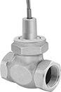
Fixed-Set-Point Flow Switches
 |
Style C |
Since they come factory set to a specific set point, these switches are easier to install than adjustable flow switches. As flowing liquid pushes an internal piston, the switch reads the position of the piston to measure the flow. When the piston passes the set point, the switch actuates. They’re accurate in any mounting position.
These switches are calibrated with and measure water accurately. They can also be used with other liquids by applying your liquid’s specific-gravity conversion factor to calculate the new set point.
Choose a fitting material that is compatible with the liquid you intend to run through your line.
Straight
|
Style C |
Bronze Fitting—Bronze and 316 stainless steel fittings resist impact better than plastic fittings.
SPDT—SPDT (single pole, double throw) switches can either turn one device from off to on (normally open) or from on to off (normally closed).
Conduit | |||||||||||||||||
|---|---|---|---|---|---|---|---|---|---|---|---|---|---|---|---|---|---|
Style | Pipe Size | Thread Type | Gender | Set Point, gpm | Approx. Difference Between Set Point and Reset Point, gpm | Max. Pressure @ Temp. | Temp. Range, ° F | Max. Switching Current @ Voltage | Trade Size | Thread Type | Gender | End-to-End Lg. | Mounting Position | Each | |||
Bronze Body with Bronze Fittings | |||||||||||||||||
SPDT | |||||||||||||||||
| C | 1 1/4 | NPT | Female | 1 | 0.15 | 400 psi @ 70° F | -20 to 300 | 400 mA @ 30V AC 170 mA @ 120V AC 80 mA @ 240V AC 300 mA @ 30V DC 130 mA @ 120V DC 60 mA @ 240V DC | 1/2 | NPT | Male | 4" | Any Angle | 6486T231 | 0000000 | ||
| C | 1 1/4 | NPT | Female | 4 | 0.6 | 400 psi @ 70° F | -20 to 300 | 400 mA @ 30V AC 170 mA @ 120V AC 80 mA @ 240V AC 300 mA @ 30V DC 130 mA @ 120V DC 60 mA @ 240V DC | 1/2 | NPT | Male | 4" | Any Angle | 6486T232 | 000000 | ||
| C | 1 1/4 | NPT | Female | 20 | 3 | 400 psi @ 70° F | -20 to 300 | 400 mA @ 30V AC 170 mA @ 120V AC 80 mA @ 240V AC 300 mA @ 30V DC 130 mA @ 120V DC 60 mA @ 240V DC | 1/2 | NPT | Male | 4" | Any Angle | 6486T235 | 000000 | ||
Fixed-Set-Point Hazardous-Location Flow Switches
 |
Safe to use where flammable gases and combustible dust may be present, these switches activate or deactivate when your flow reaches a factory-set level. All are UL listed for hazardous environments. Because their set point is fixed, they’re ready to go, making them easy to install. They actuate when your flowing liquid or gas pushes their paddle into a set position. These switches are single pole, double throw (SPDT) and can turn one device from off to on (normally open) or from on to off (normally closed). They must be mounted horizontally to function accurately.
These switches are calibrated with water and air. They can also be used with other liquids and gases but may not measure accurately if their viscosity is significantly different.
Set Point | Conduit | |||||||||||||||
|---|---|---|---|---|---|---|---|---|---|---|---|---|---|---|---|---|
Pipe Connections | For Liquids, gpm | For Gas, scfm | Max. Pressure @ Temp. | Temp. Range, ° F | Voltage, V AC | Max. Switching Current @ Voltage | Trade Size | Thread Type | Gender | End-to-End Lg. | Enclosure Rating | Certification | Each | |||
Brass Body with Threaded Brass Fittings | ||||||||||||||||
| 1 1/4 NPT Female | 4 | 21 | 250 psi @ 70° F | -4 to 220 | 120/240 | 5 amp @ 120V AC | 3/4 | NPT | Male | 2 5/8" | NEMA 4 | UL Listed CE Marked | 47565K34 | 0000000 | ||
Fixed-Set-Point Insertion-Mount Flow Switches
 |
Easy to install, these flow switches come already set to a specific set point and don’t require you to disassemble your pipeline. Instead of mounting them inline, insert them into an unthreaded PVC pipe tee or pipe outlet in large-diameter pipe. They have a paddle that’s pushed as your liquid moves through to determine flow. When the paddle reaches a set position determined by the set point, it activates or deactivates equipment. All are single pole, double throw (SPDT) and can either turn one device from off to on (normally open) or on to off (normally closed). IP rated, they seal out dust and can be lightly rinsed.
They should be mounted vertically into a horizontal pipeline, so liquid pushes the paddle. Secure them with PVC cement and primer (not included).
These flow switches are calibrated with water. You can use them with other liquids, but they may not measure accurately if the liquid’s viscosity differs from water.
Pipe Connections | For Pipe Size | Set Point, gpm | Max. Flow Rate, gpm | Max. Pressure @ Temp. | Temp. Range, ° F | Voltage | Max. Switching Current @ Voltage | Body Ht. | Enclosure Rating | Specs. Met | Each | |||
|---|---|---|---|---|---|---|---|---|---|---|---|---|---|---|
Noryl Body with Socket-Connect PVC Fittings | ||||||||||||||
| 3/4 | 1 1 1/4 | 2.7, 6.8 | 31, 40 | 160 psi @ 70° F | -13 to 212 | 230V AC/48V DC | 1 amp @ 230V AC 1 amp @ 48V DC | 2 1/2" | IP65 | UL 508 | 2766K115 | 0000000 | ||
Flow Sights for Water and Oil
 |
Visually confirm flow and inspect the color and clarity of your process media. These sights have a back window that can be backlit to increase the visibility of dark liquids.
Window | ||||||||||||||
|---|---|---|---|---|---|---|---|---|---|---|---|---|---|---|
Pipe Size | Thread Type | Gender | Temp. Range, ° F | Dia. | Type | End-to-End Lg. | Ht. | Max. Pressure @ Temp. | Direction of Flow | For Use With | Each | |||
No Indicator | ||||||||||||||
Bronze Body | ||||||||||||||
| 1 1/4 | NPT | Female | -20 to 200 | 2" | Front and Back | 4 3/8" | 3 1/8" | 125 psi @ 70° F | Any Direction | Water, Oil | 4206K26 | 0000000 | ||
High-Temperature Flow Sights for Water and Oil
 |
Flapper Indicator |
Withstand twice the temperature of standard flow sights for applications with temperatures up to 400° F. These sights let you visually confirm flow and inspect liquid color and clarity. The flapper indicator moves when flow is present, so it’s easy to confirm flow from a distance. Backlight the back window to increase the visibility of dark liquids. The brass body of these sights resists corrosion.
Window | |||||||||||||||
|---|---|---|---|---|---|---|---|---|---|---|---|---|---|---|---|
Pipe Size | Thread Type | Gender | Temp. Range, ° F | Dia. | Type | End-to-End Lg. | Ht. | Max. Pressure @ Temp. | Direction of Flow | Indicator Material | For Use With | Each | |||
Flapper Indicator | |||||||||||||||
Brass Body | |||||||||||||||
| 1 1/4 | NPT | Female | 0 to 400 | 2 5/8" | Front and Back | 5 3/8" | 3 1/8" | 150 psi @ 70° F | Any Direction | 304 Stainless Steel | Water, Oil | 4213K145 | 0000000 | ||
Full-View Flow Sights with Indicator for Water and Oil
 |
A ball indicator moves when flow is present so you can confirm flow at a distance. The large tubular window provides an unobstructed view for checking liquid movement, clarity, and color from multiple angles.
Window | Indicator | |||||||||||||||
|---|---|---|---|---|---|---|---|---|---|---|---|---|---|---|---|---|
Pipe Size | Thread Type | Gender | Temp. Range, ° F | Lg. | Type | End-to-End Lg. | Ht. | Max. Pressure @ Temp. | Direction of Flow | Material | Color | For Use With | Each | |||
Ball Indicator | ||||||||||||||||
Brass Body | ||||||||||||||||
| 1 1/4 | NPTF | Female | -40 to 185 | 2 1/8" | Tubular | 5 5/8" | 3" | 100 psi @ 70° F | Bottom to Top, Left to Right, Right to Left | Nylon | White | Water, Oil | 4470K27 | 0000000 | ||
