


Filter by
Maximum Flow
For Use With
Flow Measurement Unit
Input Voltage
Measurement Unit
Measures
Wetted Parts Material
Flow Measurement Type
Body Material
Maximum Pressure @ Temperature
Mounting Location
Fitting Material
Connects To
Circuit Protection
Export Control Classification Number (ECCN)
DFARS Specialty Metals
Communication Protocol
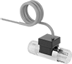
Flow Transmitters with Sight
 |
Send flow rate data using these transmitters while also being able to visually confirm liquid is flowing. They measure flow by counting how many times the turbine turns as the liquid moves through it. To prevent clogging the turbine and other damage, use them only with clean, low-viscosity liquids. These transmitters, also known as transducers, convert the flow measurement to an electrical signal that can be interpreted by receiving devices, such as remote displays and programmable logic controllers (PLCs), to monitor flow or control equipment. Mount them directly inline with your system. They measure accurately in any mounting orientation.
These transmitters are calibrated with water. You can use them with other liquids, but they may not measure accurately if the liquid’s viscosity differs from water.
Analog Transmitter Output—Transmitters with an analog output increase their output signal as flow increases. For your receiving device to interpret the signal, you will need to calibrate it for the measurement range and output signal of the transmitter. They only give accurate readings within the rated measurement range.
Digital Pulse Output—Transmitters with a digital pulse output send flow data using spikes of voltage that match the input voltage of the transmitter. The higher the flow, the more pulses they send.
Flow Measurement Type | Pipe Connections | Flow Range, gpm | End-to-End Lg. | Accuracy | Max. Pressure @ Temp. | Temp. Range, ° F | Seal Material | Input Voltage Range, V DC | Mounting Position | Field Recalibratable | Pulse Freq., Hz | Each | |||||||||||||||||||||||||||||||||||||||||||||||||||||||||||||||||||||||||||||||||||||||
|---|---|---|---|---|---|---|---|---|---|---|---|---|---|---|---|---|---|---|---|---|---|---|---|---|---|---|---|---|---|---|---|---|---|---|---|---|---|---|---|---|---|---|---|---|---|---|---|---|---|---|---|---|---|---|---|---|---|---|---|---|---|---|---|---|---|---|---|---|---|---|---|---|---|---|---|---|---|---|---|---|---|---|---|---|---|---|---|---|---|---|---|---|---|---|---|---|---|---|---|
One 4-20 mA Analog Transmitter Output—Wire Lead Connection | |||||||||||||||||||||||||||||||||||||||||||||||||||||||||||||||||||||||||||||||||||||||||||||||||||
316 Stainless Steel Body with 316 Stainless Steel Fitting | |||||||||||||||||||||||||||||||||||||||||||||||||||||||||||||||||||||||||||||||||||||||||||||||||||
| Turbine | 3/4 NPT Female | 1.5 to 15 | 5 1/4" | -2% to 2% | 200 psi @ 70° F | 20 to 212 | Buna-N | 12 to 24 | Any Angle | No | — | 00000000 | 000000000 | ||||||||||||||||||||||||||||||||||||||||||||||||||||||||||||||||||||||||||||||||||||||
| Turbine | 3/4 NPT Female | 5 to 50 | 5 1/4" | -2% to 2% | 200 psi @ 70° F | 20 to 212 | Buna-N | 12 to 24 | Any Angle | No | — | 00000000 | 00000000 | ||||||||||||||||||||||||||||||||||||||||||||||||||||||||||||||||||||||||||||||||||||||
One 0-5V DC Analog Transmitter Output—Wire Lead Connection | |||||||||||||||||||||||||||||||||||||||||||||||||||||||||||||||||||||||||||||||||||||||||||||||||||
316 Stainless Steel Body with 316 Stainless Steel Fitting | |||||||||||||||||||||||||||||||||||||||||||||||||||||||||||||||||||||||||||||||||||||||||||||||||||
| Turbine | 3/4 NPT Female | 1.5 to 15 | 5 1/4" | -2% to 2% | 200 psi @ 70° F | 20 to 212 | Buna-N | 12 to 24 | Any Angle | No | — | 00000000 | 00000000 | ||||||||||||||||||||||||||||||||||||||||||||||||||||||||||||||||||||||||||||||||||||||
| Turbine | 3/4 NPT Female | 5 to 50 | 5 1/4" | -2% to 2% | 200 psi @ 70° F | 20 to 212 | Buna-N | 12 to 24 | Any Angle | No | — | 00000000 | 00000000 | ||||||||||||||||||||||||||||||||||||||||||||||||||||||||||||||||||||||||||||||||||||||
One Digital Pulse Output—Wire Lead Connection | |||||||||||||||||||||||||||||||||||||||||||||||||||||||||||||||||||||||||||||||||||||||||||||||||||
316 Stainless Steel Body with 316 Stainless Steel Fitting | |||||||||||||||||||||||||||||||||||||||||||||||||||||||||||||||||||||||||||||||||||||||||||||||||||
| Turbine | 3/4 NPT Female | 5 to 30 | 3 15/16" | -15% to 15% | 200 psi @ 70° F | 33 to 212 | Fluoroelastomer | 4.5 to 24 | Any Angle | No | 15 to 225 | 0000000 | 000000 | ||||||||||||||||||||||||||||||||||||||||||||||||||||||||||||||||||||||||||||||||||||||
Flow Transmitters
 |
Variable Area Flow Measurement |
 |
Turbine Flow Measurement |
Send flow rate measurements to monitor and control equipment. Also known as transducers, these transmitters convert flow rate measurements to an electrical signal that can be interpreted by receiving devices, such as remote displays and programmable logic controllers (PLCs). As flow increases, the output signal increases. For your receiving device to interpret the signal, you will need to calibrate it for the measurement range and output signal of the transmitter. They only give accurate readings within the rated measurement range. Mount them directly inline with your system. They measure flow correctly no matter their mounting orientation.
These transmitters are calibrated with water. You can use them with other liquids, but they may not measure accurately if the liquid’s viscosity differs from water.
Variable Area Flow Measurement—Variable-area transmitters determine flow rate by tracking where the liquid pushes an internal piston.
Turbine Flow Measurement—Turbine transmitters measure flow by counting how many times their turbine turns as liquid passes through. To avoid clogging the turbine and other damage, use them only with clean, low-viscosity liquids. The digital output sends flow data with a pulse, which is a spike of voltage. The higher the flow, the more pulses they send. The voltage of the pulse output matches the input voltage sent to the transmitters. These transmitters meet NSF/ANSI 61 for use with drinking water.
Flow Measurement Type | Pipe Connections | Flow Range, gpm | End-to-End Lg. | Accuracy | Max. Pressure @ Temp. | Temp. Range, ° F | Seal Material | Input Voltage Range, V DC | Mounting Position | Field Recalibratable | Enclosure Rating | Pulse Freq., Hz | Each | ||||||||||||||||||||||||||||||||||||||||||||||||||||||||||||||||||||||||||||||||||||||
|---|---|---|---|---|---|---|---|---|---|---|---|---|---|---|---|---|---|---|---|---|---|---|---|---|---|---|---|---|---|---|---|---|---|---|---|---|---|---|---|---|---|---|---|---|---|---|---|---|---|---|---|---|---|---|---|---|---|---|---|---|---|---|---|---|---|---|---|---|---|---|---|---|---|---|---|---|---|---|---|---|---|---|---|---|---|---|---|---|---|---|---|---|---|---|---|---|---|---|---|
One 4-20 mA Analog Transmitter Output—4-Pole Micro M12 Connection Plug | |||||||||||||||||||||||||||||||||||||||||||||||||||||||||||||||||||||||||||||||||||||||||||||||||||
316L Stainless Steel/Aluminum/Brass/Plastic Body with 316 Stainless Steel/Brass Fitting | |||||||||||||||||||||||||||||||||||||||||||||||||||||||||||||||||||||||||||||||||||||||||||||||||||
| Variable Area | 3/4 NPT Female | 0.2 to 4 | 2 15/16" | -5% to 5% | 580 psi @ 212° F | 14 to 212 | Fluoroelastomer | 18 to 32 | Any Angle | No | IP65, IP67 | — | 00000000 | 0000000 | |||||||||||||||||||||||||||||||||||||||||||||||||||||||||||||||||||||||||||||||||||||
| Variable Area | 3/4 NPT Female | 0.2 to 6 | 2 15/16" | -5% to 5% | 580 psi @ 212° F | 14 to 212 | Fluoroelastomer | 18 to 32 | Any Angle | No | IP65, IP67 | — | 00000000 | 000000 | |||||||||||||||||||||||||||||||||||||||||||||||||||||||||||||||||||||||||||||||||||||
| Variable Area | 3/4 NPT Female | 0.2 to 10 | 2 15/16" | -5% to 5% | 580 psi @ 212° F | 14 to 212 | Fluoroelastomer | 18 to 32 | Any Angle | No | IP65, IP67 | — | 00000000 | 000000 | |||||||||||||||||||||||||||||||||||||||||||||||||||||||||||||||||||||||||||||||||||||
One 4-20 mA Analog Transmitter/Digital Pulse Output—Wire Lead Connection | |||||||||||||||||||||||||||||||||||||||||||||||||||||||||||||||||||||||||||||||||||||||||||||||||||
Nylon Body with Nylon Fitting | |||||||||||||||||||||||||||||||||||||||||||||||||||||||||||||||||||||||||||||||||||||||||||||||||||
| Turbine | 3/4 NPT Male | 1.32 to 17.17 | 2 15/16" | -3% to 3% | 362 psi @ 212° F | -4 to 212 | — | 5 to 24 | Any Angle | No | — | 17 to 227 | 00000000 | 000000 | |||||||||||||||||||||||||||||||||||||||||||||||||||||||||||||||||||||||||||||||||||||
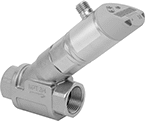
Flow and Temperature Transmitters
 |
Variable Area Flow Measurement |
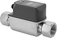 |
Vortex Flow Measurement |
Send flow rate and temperature measurements simultaneously to a programmable logic controller (PLC), data logger, or other receiving device. Used to monitor status or control equipment, these transmitters, also known as transducers, convert measurements to an electrical signal that is interpreted by receiving devices. As flow or temperature increases, the output signal increases. For your receiving device to interpret the signal, you will need to calibrate it for the measurement range and output signal of the transmitter. They only give accurate readings within the rated measurement range. Mount them inline with your pipe system. They’ll measure flow correctly in any mounting orientation.
A digital display makes it easy to view readings and adjust settings at the source. To change settings and receive error messages remotely from your PLC or computer, program one of the outputs to use IO Link. You’ll need an IO Link controller (not included) to connect to your interface.
Variable Area Flow Measurement—Variable-area transmitters determine the flow rate by tracking where the liquid pushes the piston. They have two configurable outputs. One can be wired as an analog output or a digital switch. The other one can be wired as a digital switch, digital pulse output, or IO Link. Pulse outputs send flow data using spikes of voltage that match the input voltage of the transmitter. The higher the flow, the more pulses they send. These transmitters are calibrated with water, glycol solutions, and coolants but can be recalibrated in the field for other liquids.
Vortex Flow Measurement—Vortex transmitters determine the flow rate by measuring the size of the vortex created as liquid flows through them. They don’t have any moving parts that can break or get stuck. Use them only with liquids that are at least 95% water. They have one analog output for flow and another for temperature. The output for temperature can also be wired for IO Link.
Flow Measurement Type | Pipe Connections | Flow Range, gph | End-to-End Lg. | Accuracy | Max. Pressure @ Temp. | Temp. Range, ° F | Seal Material | Input Voltage Range, V DC | Mounting Position | Field Recalibratable | Enclosure Rating | Each | |||||||||||||||||||||||||||||||||||||||||||||||||||||||||||||||||||||||||||||||||||||||
|---|---|---|---|---|---|---|---|---|---|---|---|---|---|---|---|---|---|---|---|---|---|---|---|---|---|---|---|---|---|---|---|---|---|---|---|---|---|---|---|---|---|---|---|---|---|---|---|---|---|---|---|---|---|---|---|---|---|---|---|---|---|---|---|---|---|---|---|---|---|---|---|---|---|---|---|---|---|---|---|---|---|---|---|---|---|---|---|---|---|---|---|---|---|---|---|---|---|---|---|
One Digital Switch/Pulse Output and One 4-20 mA Analog Transmitter/Digital Switch Output—4-Pole Micro M12 Connection Plug | |||||||||||||||||||||||||||||||||||||||||||||||||||||||||||||||||||||||||||||||||||||||||||||||||||
316 Stainless Steel Body with 316 Stainless Steel Fitting | |||||||||||||||||||||||||||||||||||||||||||||||||||||||||||||||||||||||||||||||||||||||||||||||||||
| Variable Area | 3/4 NPT Female | 5 to 240 | 5 9/16" | -5% to 5% | 580 psi @ 70° F | 14 to 212 | Fluoroelastomer | 18 to 30 | Any Angle | Yes | IP65, IP67 | 0000000 | 0000000 | ||||||||||||||||||||||||||||||||||||||||||||||||||||||||||||||||||||||||||||||||||||||
| Variable Area | 3/4 NPT Female | 7 to 360 | 5 9/16" | -5% to 5% | 580 psi @ 70° F | 14 to 212 | Fluoroelastomer | 18 to 30 | Any Angle | Yes | IP65, IP67 | 0000000 | 000000 | ||||||||||||||||||||||||||||||||||||||||||||||||||||||||||||||||||||||||||||||||||||||
| Variable Area | 3/4 NPT Female | 10 to 600 | 5 9/16" | -5% to 5% | 580 psi @ 70° F | 14 to 212 | Fluoroelastomer | 18 to 30 | Any Angle | Yes | IP65, IP67 | 0000000 | 000000 | ||||||||||||||||||||||||||||||||||||||||||||||||||||||||||||||||||||||||||||||||||||||
Two 4-20 mA Analog Transmitter Outputs—4-Pole Micro M12 Connection Plugs | |||||||||||||||||||||||||||||||||||||||||||||||||||||||||||||||||||||||||||||||||||||||||||||||||||
316 Stainless Steel Body with 316 Stainless Steel Fitting | |||||||||||||||||||||||||||||||||||||||||||||||||||||||||||||||||||||||||||||||||||||||||||||||||||
| Vortex | 3/4 NPT Female | 80 to 1,585 | 5 15/32" | -2% to 2% | 172 psi @ 70° F | 14 to 190 | Fluoroelastomer | 18 to 30 | Any Angle | No | IP65, IP67 | 0000000 | 000000 | ||||||||||||||||||||||||||||||||||||||||||||||||||||||||||||||||||||||||||||||||||||||
Noncontact Flow Transmitters
 |
Using ultrasonic waves, these transmitters measure the flow rate of your liquid from outside your pipe. They're a good choice for applications where you need to retrofit your system or avoid liquid coming into contact with the transmitter. Also known as transducers, these transmitters convert measurements to an electrical pulse that can be interpreted by receiving devices, such as remote displays and programmable logic controllers (PLCs). The pulse outputs match the input voltage of the transmitter. The higher the flow, the more pulses they send. For your receiving device to interpret the signal, you will need to calibrate it for the measurement range and output signal of the transmitter. They only give accurate readings within the rated measurement range. Configure them for either a 4-20mA or digital pulse output when installing.
A digital display makes it easy to check flow rate and configure settings. Clamp these transmitters onto your pipe with the included mounting hardware and gel pads. They measure flow no matter the mounting orientation.
These transmitters are calibrated with water but can be used with other liquids and will generally measure accurately, even if they differ in viscosity and density. You can recalibrate them in the field for accurate readings on pipe and operating conditions.
Flow Range for Pipe Size, gpm | Input Voltage | ||||||||||||||||||||||||||||||||||||||||||||||||||||||||||||||||||||||||||||||||||||||||||||||||||
|---|---|---|---|---|---|---|---|---|---|---|---|---|---|---|---|---|---|---|---|---|---|---|---|---|---|---|---|---|---|---|---|---|---|---|---|---|---|---|---|---|---|---|---|---|---|---|---|---|---|---|---|---|---|---|---|---|---|---|---|---|---|---|---|---|---|---|---|---|---|---|---|---|---|---|---|---|---|---|---|---|---|---|---|---|---|---|---|---|---|---|---|---|---|---|---|---|---|---|---|
Flow Measurement Type | For Pipe Size | 3/4 | 2 | 4 | End-to-End Lg. | Accuracy | Temp. Range, ° F | Min., V DC | Max. | Mounting Position | Field Recalibratable | Enclosure Rating | Each | ||||||||||||||||||||||||||||||||||||||||||||||||||||||||||||||||||||||||||||||||||||||
One Digital Pulse Output and One 4-20 mA Analog Transmitter Output—Wire Lead Connection | |||||||||||||||||||||||||||||||||||||||||||||||||||||||||||||||||||||||||||||||||||||||||||||||||||
Polycarbonate Body | |||||||||||||||||||||||||||||||||||||||||||||||||||||||||||||||||||||||||||||||||||||||||||||||||||
| Ultrasonic | 3/4 to 4 | 0 to 45 | 0 to 320 | 0 to 1,285 | 9 3/4" | -3% to 3% | 32 to 185 | 12 | 24V AC/24V DC | Any Angle | Yes | IP54 | 0000000 | 000000000 | |||||||||||||||||||||||||||||||||||||||||||||||||||||||||||||||||||||||||||||||||||||
High-Accuracy Flow and Temperature Transmitters
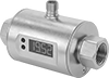 |
Also known as magmeters, these transmitters use a magnetic field to measure flow rate and temperature with high accuracy. Because they use a magnetic field, they only work with conductive liquids, such as water. These transmitters, also known as transducers, convert measurements to an electrical signal that can be interpreted by receiving devices, such as remote displays and programmable logic controllers (PLCs) to monitor flow or control equipment. For your receiving device to interpret the signal, you will need to calibrate it for the measurement range and output signal of the transmitter. As flow or temperature increases, the output signal increases. These transmitters have one analog output for flow and another for temperature. They only give accurate readings within the rated measurement range. A digital display makes it easy to view readings and adjust settings at the source. Mount these transmitters inline with your pipe system. They measure flow correctly in any mounting orientation.
These transmitters are calibrated with water. They can only be used with liquids with a conductivity of at least 20 µS/cm.
Flow Range | |||||||||||||||||||||||||||||||||||||||||||||||||||||||||||||||||||||||||||||||||||||||||||||||||||
|---|---|---|---|---|---|---|---|---|---|---|---|---|---|---|---|---|---|---|---|---|---|---|---|---|---|---|---|---|---|---|---|---|---|---|---|---|---|---|---|---|---|---|---|---|---|---|---|---|---|---|---|---|---|---|---|---|---|---|---|---|---|---|---|---|---|---|---|---|---|---|---|---|---|---|---|---|---|---|---|---|---|---|---|---|---|---|---|---|---|---|---|---|---|---|---|---|---|---|---|
Flow Measurement Type | Pipe Connections | Gallons per Minute, gpm | Liters per Minute, L/min | End-to-End Lg. | Accuracy | Max. Pressure @ Temp. | Temp. Range, ° F | Input Voltage Range, V DC | Mounting Position | Field Recalibratable | Enclosure Rating | Each | |||||||||||||||||||||||||||||||||||||||||||||||||||||||||||||||||||||||||||||||||||||||
Two 4-20 mA Analog Transmitter Outputs—4-Pole Micro M12 Connection Plugs | |||||||||||||||||||||||||||||||||||||||||||||||||||||||||||||||||||||||||||||||||||||||||||||||||||
316 Stainless Steel/Plastic/Polybutylene Body with 316 Stainless Steel Fitting | |||||||||||||||||||||||||||||||||||||||||||||||||||||||||||||||||||||||||||||||||||||||||||||||||||
| Magnetic Induction | 3/4 NPT Female | 0.02 to 13.22 | 0.2 to 50 | 2 1/8" | -2% to 2% | 225 psi @ 70° F | 0 to 175 | 20 to 30 | Any Angle | No | IP67 | 00000000 | 0000000 | ||||||||||||||||||||||||||||||||||||||||||||||||||||||||||||||||||||||||||||||||||||||
