


Filter by
Body Material
Measures
Flow Measurement Unit
Maximum Pressure @ Temperature
Fitting Material
Flow Measurement Type
Connects To
Measurement Unit
Fitting Connection
Output Current
Export Control Classification Number (ECCN)
DFARS Specialty Metals
Mounting Location
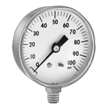
Flow Transmitters with Sight
 |
Flow Measurement Type | Pipe Connections | Flow Range, gpm | End-to-End Lg. | Accuracy | Max. Pressure @ Temp. | Temp. Range, ° F | Seal Material | Input Voltage Range, V DC | Mounting Position | Field Recalibratable | Pulse Freq., Hz | Pulse Frequency per Volume, pulse per gal. | Each | ||||||||||||||||||||||||||||||||||||||||||||||||||||||||||||||||||||||||||||||||||||||
|---|---|---|---|---|---|---|---|---|---|---|---|---|---|---|---|---|---|---|---|---|---|---|---|---|---|---|---|---|---|---|---|---|---|---|---|---|---|---|---|---|---|---|---|---|---|---|---|---|---|---|---|---|---|---|---|---|---|---|---|---|---|---|---|---|---|---|---|---|---|---|---|---|---|---|---|---|---|---|---|---|---|---|---|---|---|---|---|---|---|---|---|---|---|---|---|---|---|---|---|
One 4-20 mA Analog Transmitter Output—Wire Lead Connection | |||||||||||||||||||||||||||||||||||||||||||||||||||||||||||||||||||||||||||||||||||||||||||||||||||
Glass-Filled Polypropylene Body with Glass-Filled Polypropylene Fitting | |||||||||||||||||||||||||||||||||||||||||||||||||||||||||||||||||||||||||||||||||||||||||||||||||||
| Turbine | 1/2 NPT Female | 0.25 to 2.5 | 3 11/16" | ±2% | 150 psi @ 70° F | 20 to 150 | Buna-N | 12 to 24 | Any Angle | No | — | — | 9687K141 | 0000000 | |||||||||||||||||||||||||||||||||||||||||||||||||||||||||||||||||||||||||||||||||||||
| Turbine | 1/2 NPT Female | 0.5 to 5 | 3 11/16" | ±2% | 150 psi @ 70° F | 20 to 150 | Buna-N | 12 to 24 | Any Angle | No | — | — | 9687K142 | 000000 | |||||||||||||||||||||||||||||||||||||||||||||||||||||||||||||||||||||||||||||||||||||
| Turbine | 1/2 NPT Female | 1.5 to 15 | 3 11/16" | ±2% | 150 psi @ 70° F | 20 to 150 | Buna-N | 12 to 24 | Any Angle | No | — | — | 9687K143 | 000000 | |||||||||||||||||||||||||||||||||||||||||||||||||||||||||||||||||||||||||||||||||||||
316 Stainless Steel Body with 316 Stainless Steel Fitting | |||||||||||||||||||||||||||||||||||||||||||||||||||||||||||||||||||||||||||||||||||||||||||||||||||
| Turbine | 1/2 NPT Female | 0.25 to 2.5 | 3 11/16" | ±2% | 200 psi @ 70° F | 20 to 212 | Buna-N | 12 to 24 | Any Angle | No | — | — | 9687K191 | 00000000 | |||||||||||||||||||||||||||||||||||||||||||||||||||||||||||||||||||||||||||||||||||||
| Turbine | 1/2 NPT Female | 0.5 to 5 | 3 11/16" | ±2% | 200 psi @ 70° F | 20 to 212 | Buna-N | 12 to 24 | Any Angle | No | — | — | 9687K192 | 00000000 | |||||||||||||||||||||||||||||||||||||||||||||||||||||||||||||||||||||||||||||||||||||
| Turbine | 1/2 NPT Female | 1.5 to 15 | 3 11/16" | ±2% | 200 psi @ 70° F | 20 to 212 | Buna-N | 12 to 24 | Any Angle | No | — | — | 9687K193 | 00000000 | |||||||||||||||||||||||||||||||||||||||||||||||||||||||||||||||||||||||||||||||||||||
One 0-5V DC Analog Transmitter Output—Wire Lead Connection | |||||||||||||||||||||||||||||||||||||||||||||||||||||||||||||||||||||||||||||||||||||||||||||||||||
Glass-Filled Polypropylene Body with Glass-Filled Polypropylene Fitting | |||||||||||||||||||||||||||||||||||||||||||||||||||||||||||||||||||||||||||||||||||||||||||||||||||
| Turbine | 1/2 NPT Female | 0.25 to 2.5 | 3 11/16" | ±2% | 150 psi @ 70° F | 20 to 150 | Buna-N | 12 to 24 | Any Angle | No | — | — | 9687K131 | 000000 | |||||||||||||||||||||||||||||||||||||||||||||||||||||||||||||||||||||||||||||||||||||
| Turbine | 1/2 NPT Female | 0.5 to 5 | 3 11/16" | ±2% | 150 psi @ 70° F | 20 to 150 | Buna-N | 12 to 24 | Any Angle | No | — | — | 9687K132 | 000000 | |||||||||||||||||||||||||||||||||||||||||||||||||||||||||||||||||||||||||||||||||||||
| Turbine | 1/2 NPT Female | 1.5 to 15 | 3 11/16" | ±2% | 150 psi @ 70° F | 20 to 150 | Buna-N | 12 to 24 | Any Angle | No | — | — | 9687K133 | 000000 | |||||||||||||||||||||||||||||||||||||||||||||||||||||||||||||||||||||||||||||||||||||
316 Stainless Steel Body with 316 Stainless Steel Fitting | |||||||||||||||||||||||||||||||||||||||||||||||||||||||||||||||||||||||||||||||||||||||||||||||||||
| Turbine | 1/2 NPT Female | 0.25 to 2.5 | 3 11/16" | ±2% | 200 psi @ 70° F | 20 to 212 | Buna-N | 12 to 24 | Any Angle | No | — | — | 9687K161 | 000000 | |||||||||||||||||||||||||||||||||||||||||||||||||||||||||||||||||||||||||||||||||||||
| Turbine | 1/2 NPT Female | 0.5 to 5 | 3 11/16" | ±2% | 200 psi @ 70° F | 20 to 212 | Buna-N | 12 to 24 | Any Angle | No | — | — | 9687K162 | 000000 | |||||||||||||||||||||||||||||||||||||||||||||||||||||||||||||||||||||||||||||||||||||
| Turbine | 1/2 NPT Female | 1.5 to 15 | 3 11/16" | ±2% | 200 psi @ 70° F | 20 to 212 | Buna-N | 12 to 24 | Any Angle | No | — | — | 9687K163 | 000000 | |||||||||||||||||||||||||||||||||||||||||||||||||||||||||||||||||||||||||||||||||||||
One Digital Pulse Output—Wire Lead Connection | |||||||||||||||||||||||||||||||||||||||||||||||||||||||||||||||||||||||||||||||||||||||||||||||||||
Polypropylene Body with Polypropylene Fitting | |||||||||||||||||||||||||||||||||||||||||||||||||||||||||||||||||||||||||||||||||||||||||||||||||||
| Turbine | 1/2 NPT Female | 1.5 to 20 | 3 1/16" | ±15% | 100 psi @ 70° F | 33 to 180 | Fluoroelastomer | 4.25 to 24 | Any Angle | No | 15 to 225 | — | 9687K12 | 000000 | |||||||||||||||||||||||||||||||||||||||||||||||||||||||||||||||||||||||||||||||||||||
Brass Body with Brass Fitting | |||||||||||||||||||||||||||||||||||||||||||||||||||||||||||||||||||||||||||||||||||||||||||||||||||
| Turbine | 1/2 NPT Female | 1.5 to 20 | 3" | ±15% | 200 psi @ 70° F | 33 to 212 | Fluoroelastomer | 4.5 to 24 | Any Angle | No | 15 to 225 | — | 9687K22 | 000000 | |||||||||||||||||||||||||||||||||||||||||||||||||||||||||||||||||||||||||||||||||||||
316 Stainless Steel Body with 316 Stainless Steel Fitting | |||||||||||||||||||||||||||||||||||||||||||||||||||||||||||||||||||||||||||||||||||||||||||||||||||
| Turbine | 1/2 NPT Female | 0.25 to 2.5 | 3 11/16" | ±2% | 200 psi @ 70° F | 20 to 212 | Buna-N | 12 to 24 | Any Angle | No | — | 200 | 9687K151 | 000000 | |||||||||||||||||||||||||||||||||||||||||||||||||||||||||||||||||||||||||||||||||||||
| Turbine | 1/2 NPT Female | 1.5 to 20 | 3" | ±15% | 200 psi @ 70° F | 33 to 212 | Fluoroelastomer | 4.5 to 24 | Any Angle | No | 15 to 225 | — | 9687K32 | 000000 | |||||||||||||||||||||||||||||||||||||||||||||||||||||||||||||||||||||||||||||||||||||
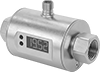
High-Accuracy Flow and Temperature Transmitters
 |
Flow Range | |||||||||||||||||||||||||||||||||||||||||||||||||||||||||||||||||||||||||||||||||||||||||||||||||||
|---|---|---|---|---|---|---|---|---|---|---|---|---|---|---|---|---|---|---|---|---|---|---|---|---|---|---|---|---|---|---|---|---|---|---|---|---|---|---|---|---|---|---|---|---|---|---|---|---|---|---|---|---|---|---|---|---|---|---|---|---|---|---|---|---|---|---|---|---|---|---|---|---|---|---|---|---|---|---|---|---|---|---|---|---|---|---|---|---|---|---|---|---|---|---|---|---|---|---|---|
Flow Measurement Type | Pipe Connections | Gallons per Minute, gpm | Liters per Minute, L/min | End-to-End Lg. | Accuracy | Max. Pressure @ Temp. | Temp. Range, ° F | Input Voltage Range, V DC | Mounting Position | Field Recalibratable | Enclosure Rating | Each | |||||||||||||||||||||||||||||||||||||||||||||||||||||||||||||||||||||||||||||||||||||||
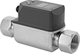
Two 4-20 mA Analog Transmitter Outputs—4-Pole M12 Connection Plugs | |||||||||||||||||||||||||||||||||||||||||||||||||||||||||||||||||||||||||||||||||||||||||||||||||||
316 Stainless Steel/Plastic/Polybutylene Body with 316 Stainless Steel Fitting | |||||||||||||||||||||||||||||||||||||||||||||||||||||||||||||||||||||||||||||||||||||||||||||||||||
| Magnetic Induction | 1/2 NPT Female | 0.03 to 6.6 | 0.1 to 25 | 2 1/8" | ±2% | 225 psi @ 70° F | 0 to 175 | 20 to 30 | Any Angle | No | IP67 | 4397N101 | 0000000 | ||||||||||||||||||||||||||||||||||||||||||||||||||||||||||||||||||||||||||||||||||||||
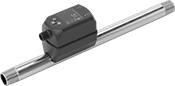
Flow, Pressure, and Temperature Transmitters for Gases
 |
Flow Measurement Type | Pipe Connections | Flow Range, scfm | End-to-End Lg. | Accuracy | Max. Pressure @ Temp. | Temp. Range, ° F | Seal Material | Input Voltage Range, V DC | Mounting Position | Field Recalibratable | Enclosure Rating | Each | |||||||||||||||||||||||||||||||||||||||||||||||||||||||||||||||||||||||||||||||||||||||
|---|---|---|---|---|---|---|---|---|---|---|---|---|---|---|---|---|---|---|---|---|---|---|---|---|---|---|---|---|---|---|---|---|---|---|---|---|---|---|---|---|---|---|---|---|---|---|---|---|---|---|---|---|---|---|---|---|---|---|---|---|---|---|---|---|---|---|---|---|---|---|---|---|---|---|---|---|---|---|---|---|---|---|---|---|---|---|---|---|---|---|---|---|---|---|---|---|---|---|---|
One Digital Switch/Pulse Output and One 4-20 mA Analog Transmitter/Digital Switch/Pulse Output—4-Pole M12 Connection Plug | |||||||||||||||||||||||||||||||||||||||||||||||||||||||||||||||||||||||||||||||||||||||||||||||||||
304 Stainless Steel Body with 304 Stainless Steel Fitting | |||||||||||||||||||||||||||||||||||||||||||||||||||||||||||||||||||||||||||||||||||||||||||||||||||
| Thermal | 1/2 NPT Male | 0.15 to 44 | 11 13/16" | ±6% | 230 psi @ 70° F | 14 to 140 | Fluoroelastomer | 18 to 30 | Any Angle | No | IP65, IP67 | 4384N11 | 000000000 | ||||||||||||||||||||||||||||||||||||||||||||||||||||||||||||||||||||||||||||||||||||||
Flow and Temperature Transmitters
 |
Vortex Flow Measurement |
Flow Measurement Type | Pipe Connections | Flow Range, gph | End-to-End Lg. | Accuracy | Max. Pressure @ Temp. | Temp. Range, ° F | Seal Material | Input Voltage Range, V DC | Mounting Position | Field Recalibratable | Enclosure Rating | Each | |||||||||||||||||||||||||||||||||||||||||||||||||||||||||||||||||||||||||||||||||||||||
|---|---|---|---|---|---|---|---|---|---|---|---|---|---|---|---|---|---|---|---|---|---|---|---|---|---|---|---|---|---|---|---|---|---|---|---|---|---|---|---|---|---|---|---|---|---|---|---|---|---|---|---|---|---|---|---|---|---|---|---|---|---|---|---|---|---|---|---|---|---|---|---|---|---|---|---|---|---|---|---|---|---|---|---|---|---|---|---|---|---|---|---|---|---|---|---|---|---|---|---|
Two 4-20 mA Analog Transmitter Outputs—4-Pole M12 Connection Plugs | |||||||||||||||||||||||||||||||||||||||||||||||||||||||||||||||||||||||||||||||||||||||||||||||||||
316 Stainless Steel Body with 316 Stainless Steel Fitting | |||||||||||||||||||||||||||||||||||||||||||||||||||||||||||||||||||||||||||||||||||||||||||||||||||
| Vortex | 1/2 NPT Female | 16 to 317 | 4 11/16" | ±2% | 172 psi @ 70° F | 14 to 190 | Fluoroelastomer | 18 to 30 | Any Angle | No | IP65, IP67 | 4401N16 | 0000000 | ||||||||||||||||||||||||||||||||||||||||||||||||||||||||||||||||||||||||||||||||||||||
| Vortex | 1/2 NPT Female | 32 to 634 | 4 11/16" | ±2% | 172 psi @ 70° F | 14 to 190 | Fluoroelastomer | 18 to 30 | Any Angle | No | IP65, IP67 | 4401N17 | 000000 | ||||||||||||||||||||||||||||||||||||||||||||||||||||||||||||||||||||||||||||||||||||||
