


Filter by
For Use With
Body Material
Measures
Wetted Parts Material
Flow Measurement Unit
Fitting Material
Maximum Temperature
Maximum Pressure @ Temperature
Output Current
Measurement Unit
Fitting Connection
Input Voltage
Connects To
Flow Measurement Type
U.S.–Mexico–Canada Agreement (USMCA) Qualifying
DFARS Specialty Metals
Export Control Classification Number (ECCN)
REACH
Gender
Environment
Flow Transmitters
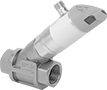 |
Variable Area Flow Measurement |
Send flow rate measurements to monitor and control equipment. Also known as transducers, these transmitters convert flow rate measurements to an electrical signal that can be interpreted by receiving devices, such as remote displays and programmable logic controllers (PLCs). As flow increases, the output signal increases. For your receiving device to interpret the signal, you will need to calibrate it for the measurement range and output signal of the transmitter. They only give accurate readings within the rated measurement range. Mount them directly inline with your system. They measure flow correctly no matter their mounting orientation.
These transmitters are calibrated with water. You can use them with other liquids, but they may not measure accurately if the liquid’s viscosity differs from water.
Variable Area Flow Measurement—Variable-area transmitters determine flow rate by tracking where the liquid pushes an internal piston.
Flow Measurement Type | Pipe Connections | Flow Range, gpm | End-to-End Lg. | Accuracy | Max. Pressure @ Temp. | Temp. Range, ° F | Seal Material | Input Voltage Range, V DC | Mounting Position | Field Recalibratable | Enclosure Rating | Each | |||
|---|---|---|---|---|---|---|---|---|---|---|---|---|---|---|---|
One 4-20 mA Analog Transmitter Output—4-Pole M12 Connection Plug | |||||||||||||||
316L Stainless Steel/Aluminum/Brass/Plastic Body with 316 Stainless Steel/Brass Fitting | |||||||||||||||
| Variable Area | 1 NPT Female | 0.5 to 27 | 3 5/8" | ±5% | 362 psi @ 212° F | 14 to 212 | Fluoroelastomer | 18 to 32 | Any Angle | No | IP65, IP67 | 4386N104 | 0000000 | ||
Two 4-20 mA Analog Transmitter Outputs—4-Pole M12 Connection Plugs | |||||||||||||||
316L Stainless Steel/Aluminum/Brass/Plastic Body with 316 Stainless Steel/Brass Fitting | |||||||||||||||
| Variable Area | 3/4 NPT Female | 0.1 to 4 | 2 15/16" | ±5% | 580 psi @ 212° F | 14 to 212 | Fluoroelastomer | 18 to 30 | Any Angle | No | IP65, IP67 | 4386N105 | 000000 | ||
| Variable Area | 3/4 NPT Female | 0.1 to 6 | 2 15/16" | ±5% | 580 psi @ 212° F | 14 to 212 | Fluoroelastomer | 18 to 30 | Any Angle | No | IP65, IP67 | 4386N106 | 000000 | ||
| Variable Area | 3/4 NPT Female | 0.2 to 10 | 2 15/16" | ±5% | 580 psi @ 212° F | 14 to 212 | Fluoroelastomer | 18 to 30 | Any Angle | No | IP65, IP67 | 4386N107 | 000000 | ||
Flow and Temperature Transmitters
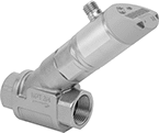 |
Variable Area Flow Measurement |
Flow Measurement Type | Pipe Connections | Flow Range, gph | End-to-End Lg. | Accuracy | Max. Pressure @ Temp. | Temp. Range, ° F | Seal Material | Input Voltage Range, V DC | Mounting Position | Field Recalibratable | Enclosure Rating | Each | |||
|---|---|---|---|---|---|---|---|---|---|---|---|---|---|---|---|
One Digital Switch/Pulse Output and One 4-20 mA Analog Transmitter/Digital Switch Output—4-Pole M12 Connection Plug | |||||||||||||||
316 Stainless Steel Body with 316 Stainless Steel Fitting | |||||||||||||||
| Variable Area | 3/4 NPT Female | 5 to 240 | 5 9/16" | ±5% | 580 psi @ 70° F | 14 to 212 | Fluoroelastomer | 18 to 30 | Any Angle | Yes | IP65, IP67 | 4401N11 | 0000000 | ||
| Variable Area | 3/4 NPT Female | 7 to 360 | 5 9/16" | ±5% | 580 psi @ 70° F | 14 to 212 | Fluoroelastomer | 18 to 30 | Any Angle | Yes | IP65, IP67 | 4401N12 | 000000 | ||
| Variable Area | 3/4 NPT Female | 10 to 600 | 5 9/16" | ±5% | 580 psi @ 70° F | 14 to 212 | Fluoroelastomer | 18 to 30 | Any Angle | Yes | IP65, IP67 | 4401N13 | 000000 | ||
| Variable Area | 1 NPT Female | 30 to 1,620 | 5 3/4" | ±5% | 362 psi @ 70° F | 14 to 212 | Fluoroelastomer | 18 to 30 | Any Angle | Yes | IP65, IP67 | 4401N14 | 000000 | ||
| Variable Area | 1 1/2 NPT Female | 60 to 3,000 | 6 3/16" | ±5% | 362 psi @ 70° F | 14 to 212 | Fluoroelastomer | 18 to 30 | Any Angle | Yes | IP65, IP67 | 4401N15 | 000000 | ||
