


Filter by
Maximum Flow
For Use With
Calibrated With
Measures
Body Material
Minimum Flow
Flow Measurement Unit
Wetted Parts Material

Connects To
Output Current
Flow Measurement Type
Fitting Material
Electrical Connection

Maximum Pressure @ Temperature
RoHS
Export Control Classification Number (ECCN)
DFARS Specialty Metals
Flow Transmitters
 |
Turbine Flow Measurement |
Flow Measurement Type | Pipe Connections | Flow Range, gpm | End-to-End Lg. | Accuracy | Max. Pressure @ Temp. | Temp. Range, ° F | Input Voltage Range, V DC | Mounting Position | Field Recalibratable | Pulse Freq., Hz | Each | |||
|---|---|---|---|---|---|---|---|---|---|---|---|---|---|---|
One Analog Transmitter/Digital Pulse Output—Wire Lead Connection | ||||||||||||||
Nylon Body with Nylon Fitting | ||||||||||||||
| Turbine | 1/4 NPT Male | 0.026 to 0.65 | 1 3/4" | ±3% | 362 psi @ 212° F | -4 to 212 | 5 to 24 | Any Angle | No | 36 to 902 | 4386N201 | 0000000 | ||
| Turbine | 3/8 NPT Male | 0.13 to 1.3 | 2 5/32" | ±3% | 362 psi @ 212° F | -4 to 212 | 5 to 24 | Any Angle | No | 56 to 565 | 4386N202 | 000000 | ||
| Turbine | 3/8 NPT Male | 0.26 to 4 | 2 5/32" | ±3% | 362 psi @ 212° F | -4 to 212 | 5 to 24 | Any Angle | No | 36 to 553 | 4386N203 | 000000 | ||
| Turbine | 3/8 NPT Male | 0.53 to 9.2 | 2 5/32" | ±3% | 362 psi @ 212° F | -4 to 212 | 5 to 24 | Any Angle | No | 25 to 435 | 4386N204 | 000000 | ||
| Turbine | 3/4 NPT Male | 1.32 to 17.17 | 2 15/16" | ±3% | 362 psi @ 212° F | -4 to 212 | 5 to 24 | Any Angle | No | 17 to 227 | 4386N205 | 000000 | ||
Brass Body with Brass Fitting | ||||||||||||||
| Turbine | 3/8 NPT Male | 0.5 to 2.11 | 2 5/32" | ±3% | 362 psi @ 212° F | -4 to 212 | 5 to 24 | Any Angle | No | 132 to 559 | 4386N206 | 000000 | ||
| Turbine | 3/8 NPT Male | 0.8 to 6.6 | 2 5/32" | ±3% | 362 psi @ 212° F | -4 to 212 | 5 to 24 | Any Angle | No | 46 to 383 | 4386N207 | 000000 | ||
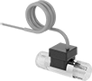
Flow Transmitters with Sight
 |
Flow Measurement Type | Pipe Connections | Flow Range, gpm | End-to-End Lg. | Accuracy | Max. Pressure @ Temp. | Temp. Range, ° F | Seal Material | Input Voltage Range, V DC | Mounting Position | Field Recalibratable | Pulse Freq., Hz | Pulse Frequency per Volume, pulse per gal. | Each | |||
|---|---|---|---|---|---|---|---|---|---|---|---|---|---|---|---|---|
One 4-20 mA Analog Transmitter Output—Wire Lead Connection | ||||||||||||||||
Glass-Filled Polypropylene Body with Glass-Filled Polypropylene Fitting | ||||||||||||||||
| Turbine | 1/2 NPT Female | 0.25 to 2.5 | 3 11/16" | ±2% | 150 psi @ 70° F | 20 to 150 | Buna-N | 12 to 24 | Any Angle | No | — | — | 9687K141 | 0000000 | ||
| Turbine | 1/2 NPT Female | 0.5 to 5 | 3 11/16" | ±2% | 150 psi @ 70° F | 20 to 150 | Buna-N | 12 to 24 | Any Angle | No | — | — | 9687K142 | 000000 | ||
| Turbine | 1/2 NPT Female | 1.5 to 15 | 3 11/16" | ±2% | 150 psi @ 70° F | 20 to 150 | Buna-N | 12 to 24 | Any Angle | No | — | — | 9687K143 | 000000 | ||
316 Stainless Steel Body with 316 Stainless Steel Fitting | ||||||||||||||||
| Turbine | 1/2 NPT Female | 0.25 to 2.5 | 3 11/16" | ±2% | 200 psi @ 70° F | 20 to 212 | Buna-N | 12 to 24 | Any Angle | No | — | — | 9687K191 | 00000000 | ||
| Turbine | 1/2 NPT Female | 0.5 to 5 | 3 11/16" | ±2% | 200 psi @ 70° F | 20 to 212 | Buna-N | 12 to 24 | Any Angle | No | — | — | 9687K192 | 00000000 | ||
| Turbine | 1/2 NPT Female | 1.5 to 15 | 3 11/16" | ±2% | 200 psi @ 70° F | 20 to 212 | Buna-N | 12 to 24 | Any Angle | No | — | — | 9687K193 | 00000000 | ||
| Turbine | 3/4 NPT Female | 1.5 to 15 | 5 1/4" | ±2% | 200 psi @ 70° F | 20 to 212 | Buna-N | 12 to 24 | Any Angle | No | — | — | 9687K201 | 00000000 | ||
| Turbine | 3/4 NPT Female | 5 to 50 | 5 1/4" | ±2% | 200 psi @ 70° F | 20 to 212 | Buna-N | 12 to 24 | Any Angle | No | — | — | 9687K202 | 00000000 | ||
| Turbine | 1 NPT Female | 1.5 to 15 | 5 1/4" | ±2% | 200 psi @ 70° F | 20 to 212 | Buna-N | 12 to 24 | Any Angle | No | — | — | 9687K211 | 00000000 | ||
| Turbine | 1 NPT Female | 5 to 50 | 5 1/4" | ±2% | 200 psi @ 70° F | 20 to 212 | Buna-N | 12 to 24 | Any Angle | No | — | — | 9687K212 | 00000000 | ||
One 0-5V DC Analog Transmitter Output—Wire Lead Connection | ||||||||||||||||
Glass-Filled Polypropylene Body with Glass-Filled Polypropylene Fitting | ||||||||||||||||
| Turbine | 1/2 NPT Female | 0.25 to 2.5 | 3 11/16" | ±2% | 150 psi @ 70° F | 20 to 150 | Buna-N | 12 to 24 | Any Angle | No | — | — | 9687K131 | 000000 | ||
| Turbine | 1/2 NPT Female | 0.5 to 5 | 3 11/16" | ±2% | 150 psi @ 70° F | 20 to 150 | Buna-N | 12 to 24 | Any Angle | No | — | — | 9687K132 | 000000 | ||
| Turbine | 1/2 NPT Female | 1.5 to 15 | 3 11/16" | ±2% | 150 psi @ 70° F | 20 to 150 | Buna-N | 12 to 24 | Any Angle | No | — | — | 9687K133 | 000000 | ||
316 Stainless Steel Body with 316 Stainless Steel Fitting | ||||||||||||||||
| Turbine | 1/2 NPT Female | 0.25 to 2.5 | 3 11/16" | ±2% | 200 psi @ 70° F | 20 to 212 | Buna-N | 12 to 24 | Any Angle | No | — | — | 9687K161 | 000000 | ||
| Turbine | 1/2 NPT Female | 0.5 to 5 | 3 11/16" | ±2% | 200 psi @ 70° F | 20 to 212 | Buna-N | 12 to 24 | Any Angle | No | — | — | 9687K162 | 000000 | ||
| Turbine | 1/2 NPT Female | 1.5 to 15 | 3 11/16" | ±2% | 200 psi @ 70° F | 20 to 212 | Buna-N | 12 to 24 | Any Angle | No | — | — | 9687K163 | 000000 | ||
| Turbine | 3/4 NPT Female | 1.5 to 15 | 5 1/4" | ±2% | 200 psi @ 70° F | 20 to 212 | Buna-N | 12 to 24 | Any Angle | No | — | — | 9687K171 | 00000000 | ||
| Turbine | 3/4 NPT Female | 5 to 50 | 5 1/4" | ±2% | 200 psi @ 70° F | 20 to 212 | Buna-N | 12 to 24 | Any Angle | No | — | — | 9687K172 | 00000000 | ||
| Turbine | 1 NPT Female | 1.5 to 15 | 5 1/4" | ±2% | 200 psi @ 70° F | 20 to 212 | Buna-N | 12 to 24 | Any Angle | No | — | — | 9687K181 | 00000000 | ||
| Turbine | 1 NPT Female | 5 to 50 | 5 1/4" | ±2% | 200 psi @ 70° F | 20 to 212 | Buna-N | 12 to 24 | Any Angle | No | — | — | 9687K182 | 00000000 | ||
One Digital Pulse Output—Wire Lead Connection | ||||||||||||||||
Polypropylene Body with Polypropylene Fitting | ||||||||||||||||
| Turbine | 1/4 NPT Female | 0.1 to 5 | 3 1/16" | ±7% | 100 psi @ 70° F | 33 to 180 | Fluoroelastomer | 4.25 to 24 | Any Angle | No | 15 to 225 | — | 9687K11 | 000000 | ||
| Turbine | 1/2 NPT Female | 1.5 to 20 | 3 1/16" | ±15% | 100 psi @ 70° F | 33 to 180 | Fluoroelastomer | 4.25 to 24 | Any Angle | No | 15 to 225 | — | 9687K12 | 000000 | ||
Brass Body with Brass Fitting | ||||||||||||||||
| Turbine | 1/4 NPT Female | 0.1 to 5 | 3" | ±7% | 200 psi @ 70° F | 33 to 212 | Fluoroelastomer | 4.5 to 24 | Any Angle | No | 15 to 225 | — | 9687K21 | 000000 | ||
| Turbine | 1/2 NPT Female | 1.5 to 20 | 3" | ±15% | 200 psi @ 70° F | 33 to 212 | Fluoroelastomer | 4.5 to 24 | Any Angle | No | 15 to 225 | — | 9687K22 | 000000 | ||
| Turbine | 1 NPT Female | 8 to 60 | 3 15/16" | ±15% | 200 psi @ 70° F | 33 to 212 | Fluoroelastomer | 4.5 to 24 | Any Angle | No | 15 to 225 | — | 9687K24 | 000000 | ||
316 Stainless Steel Body with 316 Stainless Steel Fitting | ||||||||||||||||
| Turbine | 1/2 NPT Female | 0.25 to 2.5 | 3 11/16" | ±2% | 200 psi @ 70° F | 20 to 212 | Buna-N | 12 to 24 | Any Angle | No | — | 200 | 9687K151 | 000000 | ||
| Turbine | 1/2 NPT Female | 1.5 to 20 | 3" | ±15% | 200 psi @ 70° F | 33 to 212 | Fluoroelastomer | 4.5 to 24 | Any Angle | No | 15 to 225 | — | 9687K32 | 000000 | ||
| Turbine | 3/4 NPT Female | 5 to 30 | 3 15/16" | ±15% | 200 psi @ 70° F | 33 to 212 | Fluoroelastomer | 4.5 to 24 | Any Angle | No | 15 to 225 | — | 9687K33 | 000000 | ||
| Turbine | 1 NPT Female | 8 to 60 | 3 15/16" | ±15% | 200 psi @ 70° F | 33 to 212 | Fluoroelastomer | 4.5 to 24 | Any Angle | No | 15 to 225 | — | 9687K34 | 000000 | ||
Build-Your-Own Flanged Pipe Flow Transmitters
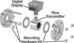 |
Components Sold Separately (Pipe Flanges Not Included) |
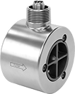
Flow Transmitters
 |
Flange | |||||||||||||||||
|---|---|---|---|---|---|---|---|---|---|---|---|---|---|---|---|---|---|
Flow Measurement Type | Pipe Size | Flow Range, gpm | Bore Size | OD | Type | For Flange ANSI Class | End-to-End Lg. | Accuracy | Max. Pressure @ Temp. | Temp. Range, ° F | Mounting Position | Field Recalibratable | Pulse Frequency per Volume, pulse per gal. | Each | |||
One Digital Pulse Output—2-Pin BNC Connection Plug | |||||||||||||||||
316/316L Stainless Steel Body with 316/316L Stainless Steel Fitting | |||||||||||||||||
| Turbine | 1 | 3 to 30 | 7/8" | 2" | Round | 150 | 4" | ±1.0% | 285 psi @ 70° F | -150 to 350 | Any Angle | No | 3,100 | 4408N11 | 0000000 | ||
| Turbine | 2 | 5 to 50 | 1" | 3 5/8" | Round | 150 | 2 1/2" | ±1.0% | 285 psi @ 70° F | -150 to 350 | Any Angle | No | 850 | 4408N12 | 00000000 | ||
| Turbine | 2 | 15 to 180 | 1 1/2" | 3 5/8" | Round | 150 | 2 1/2" | ±1.0% | 285 psi @ 70° F | -150 to 350 | Any Angle | No | 325 | 4408N13 | 00000000 | ||
| Turbine | 3 | 60 to 600 | 3" | 5" | Round | 150 | 4 1/4" | ±1.0% | 285 psi @ 70° F | -150 to 350 | Any Angle | No | 50 | 4408N14 | 00000000 | ||
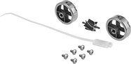 |
For Pipe Size | For Bore Size | For Flange ANSI Class | Includes | Each | ||
|---|---|---|---|---|---|---|
| 1 | 7/8" | 150 | 6 Screws, 2 Rotor Supports, One Rotor Assembly, One K-Factor Tag | 4408N19 | 0000000 | |
| 2 | 1" | 150 | 6 Screws, 2 Rotor Supports, One Rotor Assembly, One K-Factor Tag | 4408N21 | 000000 | |
| 2 | 1 1/2" | 150 | 6 Screws, 2 Rotor Supports, One Rotor Assembly, One K-Factor Tag | 4408N22 | 000000 | |
| 3 | 3" | 150 | 6 Screws, 2 Rotor Supports, One Rotor Assembly, One K-Factor Tag | 4408N23 | 00000000 |
