


How to Identify and Measure Fittings
Pipe size is an industry designation, not the actual size. View information about how to measure threaded and unthreaded pipe and pipe fittings.
More
Selecting and Measuring Expansion Joints
For information about selecting pipe size, see Selecting and Measuring Pipe & Fittings.
More
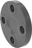
Low-Pressure Stainless Steel Unthreaded Pipe Flanges
Bolt two flat-surface flanges or two raised-surface flanges of the same size together with a
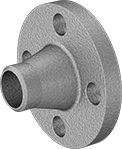
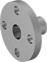
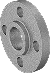
Butt-weld flanges are also known as weld-neck flanges; the flange neck has a beveled end that, when flush to pipe, creates a trough for a strong weld. Socket-connect flanges have an internal stop that supports the pipe when welding and prevents the pipe from sliding all the way through. Slip-on weld flanges have no internal stop; slide a pipe through the flange and weld on both sides. Stub-end flanges are also known as lap-joint flanges; use them with a stub-end straight adapter (not included). The stub-end straight adapter slides into the flange and welds to pipe (not the flange). Since the flange isn’t welded to the pipe, it can be disconnected easily for frequent cleaning and inspecting. Long-neck weld flanges have a square-cut end for welding directly to a pressure vessel or tank. With a longer neck than butt-weld flanges, they stick out farther from your tank wall for easier access to bolts. These flanges eliminate the need to weld a flange to a length of pipe.
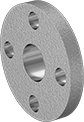
Reducing flanges let you transition your piping system to a smaller pipe size; attach to a flange with a larger pipe size but with the same flange dimensions. Cap flanges are also known as blind flanges.
Forged flanges have better strength than cast flanges. 304 stainless steel flanges offer very good corrosion resistance, and 316 stainless steel flanges have excellent corrosion resistance.
![]() For technical drawings and 3-D models, click on a part number.
For technical drawings and 3-D models, click on a part number.


- For Use With: Air, Water, Oil, Natural Gas
- Pressure Class: 150
- Specifications Met: ASTM A182, ASME B16.5
- Certification: Material Certificate with Traceable Lot Number and Test Report
- Fittings: Use schedule 40 stainless steel
- Pipe Nipples and Pipe: Use Schedule 40 stainless steel


- For Use With: Air, Water, Oil, Natural Gas
- Pressure Class: 150
- Specifications Met
4-8 pipe size: ASTM 182
All other pipe sizes: ASME B16.5, ASTM A182 - Certification: Material Certificate with Traceable Lot Number and Test Report
- Fittings: Use schedule 40 stainless steel
- Pipe Nipples and Pipe: Use Schedule 40 stainless steel


- For Use With: Air, Water, Oil, Natural Gas
- Pressure Class: 150
- Specifications Met: ASTM A182, ASME B16.5
- Certification: Material Certificate with Traceable Lot Number and Test Report
- Fittings: Use schedule 40 stainless steel
- Pipe Nipples and Pipe: Use Schedule 40 stainless steel


- For Use With: Air, Water, Oil, Natural Gas
- Pressure Class: 150
- Specifications Met: ASTM A182, ASME B16.5
- Certification: Material Certificate with Traceable Lot Number and Test Report
- Fittings: Use schedule 40 stainless steel
- Pipe Nipples and Pipe: Use Schedule 40 stainless steel
Flanges | ||||||||||||
|---|---|---|---|---|---|---|---|---|---|---|---|---|
Bolt Hole | Thin-Wall Straight Adapters | Standard-Wall Straight Adapters | ||||||||||
| Pipe Size | Flange OD | For Bolt Dia. | Dia. | No. of | Bolt Circle Dia. | Max. Pressure | Each | Each | Each | |||
304/304L Stainless Steel | ||||||||||||
| 6 | 11" | 3/4" | 7/8" | 8 | 9 1/2" | 230 psi @ 72° F | 000000000 | 0000000 | 000000000 | 0000000 | 000000000 | 0000000 |
316/316L Stainless Steel | ||||||||||||
| 6 | 11" | 3/4" | 7/8" | 8 | 9 1/2" | 230 psi @ 72° F | 000000000 | 000000 | 000000000 | 000000 | 000000000 | 000000 |


- For Use With: Air, Natural Gas, Oil, Steam, Water
- Specifications Met: ASME B16.5, ASTM A182
- Certification: Material Certificate with Traceable Lot Number and Test Report
Bolt Hole | |||||||||||
|---|---|---|---|---|---|---|---|---|---|---|---|
| Pipe Size | Construction | Flange OD | Overall Lg. | For Bolt Dia. | Dia. | No. of | Bolt Circle Dia. | Max. Pressure | Max. Steam Pressure | Each | |
304/304L Stainless Steel | |||||||||||
| 6 | Seamless | 11" | 12" | 3/4" | 0.88" | 8 | 9 1/2" | 230 psi @ 72° F | 175 psi @ 300° F | 000000000 | 000000000 |
316/316L Stainless Steel | |||||||||||
| 6 | Seamless | 11" | 12" | 3/4" | 0.88" | 8 | 9 1/2" | 230 psi @ 72° F | 175 psi @ 300° F | 000000000 | 00000000 |


- For Use With: Air, Natural Gas, Oil, Steam, Water
- Pressure Class: 150
- Specifications Met: ASME B16.5
- Fittings: Use schedule 40 stainless steel
- Pipe Nipples and Pipe: Use Schedule 40 stainless steel


- For Use With: Air, Water, Oil, Natural Gas
- Pressure Class: 150
- Specifications Met: ASTM A182, ASME B16.5
- Certification: Material Certificate with Traceable Lot Number and Test Report
- Fittings: Use schedule 40 stainless steel
- Pipe Nipples and Pipe: Use Schedule 40 stainless steel
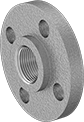
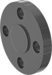
Low-Pressure Stainless Steel Threaded Pipe Flanges
Also known as Pressure Class 150 flanges, these are designed for low-pressure pipe applications. Bolt two flat-surface flanges or two raised-surface flanges of the same size together with a gasket (sold separately) to create an access point within a line.
304 stainless steel flanges have very good corrosion resistance. 316 stainless steel flanges have excellent corrosion resistance.
Forged flanges have better strength than cast flanges. They are also called ANSI flanges.
Reducing flanges allow you to transition your system to a smaller pipe size; attach to a flange with a larger pipe size but with the same flange dimensions.
![]() For technical drawings and 3-D models, click on a part number.
For technical drawings and 3-D models, click on a part number.


- For Use With: Air, Natural Gas, Oil, Steam, Water
- Pressure Class: 150
- Specifications Met:
Alloy 20 flanges: ASME B16.5
All other flanges: ASME B16.5, ASTM A182 - Fittings: Use Class 150 stainless steel
- Pipe Nipples and Pipe: Use Schedule 40 stainless steel

- For Use With: Air, Natural Gas, Oil, Steam, Water
- Pressure Class: 150
- Specifications Met: ASTM A182, ASME B16.5
- Pipe Nipples and Pipe: Use Schedule 40 stainless steel
- Fittings: Use Class 150 stainless steel
Bolt Hole | ||||||||||
|---|---|---|---|---|---|---|---|---|---|---|
| Pipe Size | For Flange Pipe Size | Flange OD | For Bolt Dia. | Dia. | No. of | Bolt Circle Dia. | Max. Pressure | Max. Steam Pressure | Each | |
304/304L Stainless Steel | ||||||||||
NPT | ||||||||||
| 4 | 6 | 11" | 3/4" | 0.88" | 8 | 9 1/2" | 230 psi @ 72° F | 150 psi @ 360° F | 000000000 | 0000000 |
316/316L Stainless Steel | ||||||||||
NPT | ||||||||||
| 4 | 6 | 11" | 3/4" | 0.88" | 8 | 9 1/2" | 230 psi @ 72° F | 150 psi @ 360° F | 000000000 | 000000 |
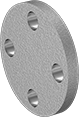
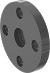
Low-Pressure Steel Unthreaded Pipe Flanges
Bolt two flat-surface flanges or two raised-surface flanges of the same size together with a gasket (sold separately) to create an access point in a pipe line. Flanges are for use with low-pressure applications in noncorrosive environments.
Butt-weld flanges are also known as weld-neck flanges. The flange neck has a beveled end that, when flush to pipe, creates a trough for a strong weld.
Slip-on weld flanges have no internal stop. Slide a pipe through the flange and weld on both sides.
Socket-connect flanges have an internal stop that supports the pipe when welding and prevents the pipe from sliding all the way through.
Long-neck weld flanges have a square-cut end for welding directly to a pressure vessel or tank. With a longer neck than butt-weld flanges, they stick out farther from your tank wall for easier access to bolts. These flanges eliminate the need to weld a flange to a length of pipe.
Reducing flanges let you transition your piping system to a smaller pipe. Attach to a flange with a larger pipe size but with the same flange dimensions.
Cap flanges are also known as blind flanges.
![]() For technical drawings and 3-D models, click on a part number.
For technical drawings and 3-D models, click on a part number.


- For Use With: Air, Natural Gas, Oil, Steam, Water
- Pressure Class: See table
- Specifications Met: See table
- Certification: See table
- Pipe Nipples and Pipe: Use Schedule 40 steel
- Fittings: Use Schedule 40 iron or steel
Bolt Hole | ||||||||||||||
|---|---|---|---|---|---|---|---|---|---|---|---|---|---|---|
| Pipe Size | Wall Thick. | Flange OD | For Bolt Dia. | Dia. | No. of | Bolt Circle Dia. | Pressure Class | Construction | Max. Pressure | Max. Steam Pressure | Certification | Specifications Met | Each | |
| 6 | 0.28" | 11" | 3/4" | 7/8" | 8 | 9 1/2" | 150 | Seamless | 285 psi @ 72° F | 150 psi @ 300° F | Material Certificate with Traceable Lot Number and Test Report | ASME B16.5, ASTM A105, MSS SP-25 | 000000000 | 000000 |


- For Use With: Air, Natural Gas, Oil, Steam, Water
- Pressure Class: See table
- Specifications Met: See table
- Certification: See table
- Pipe Nipples and Pipe: Use Schedule 40 steel
- Fittings: See Table
Bolt Hole | For Fitting | |||||||||||||
|---|---|---|---|---|---|---|---|---|---|---|---|---|---|---|
| Pipe Size | Flange OD | For Bolt Dia. | Dia. | No. of | Bolt Circle Dia. | Pressure Class | Max. Pressure | Max. Steam Pressure | Schedule | Material | Certification | Specifications Met | Each | |
| 6 | 11" | 3/4" | 7/8" | 8 | 9 1/2" | 150 | 285 psi @ 72° F | 150 psi @ 300° F | 40 | Iron, Steel | Material Certificate with Traceable Lot Number and Test Report | ASME B16.5, ASTM A105, MSS SP-25 | 000000000 | 000000 |


- For Use With: Air, Natural Gas, Oil, Steam, Water
- Pressure Class: 150
- Specifications Met: ASME B16.5, ASTM A105
- Certification: Material Certificate with Traceable Lot Number and Test Report
- Pipe Nipples and Pipe: Use Schedule 40 steel
- Fittings: Use Schedule 40 steel
Bolt Hole | ||||||||||
|---|---|---|---|---|---|---|---|---|---|---|
| Pipe Size | For Flange Pipe Size | Flange OD | For Bolt Dia. | Dia. | No. of | Bolt Circle Dia. | Max. Pressure | Max. Steam Pressure | Each | |
| 4 | 6 | 11" | 3/4" | 7/8" | 8 | 9 1/2" | 285 psi @ 72° F | 230 psi @ 300° F | 00000000 | 0000000 |

- For Use With: Air, Natural Gas, Oil, Steam, Water
- Pressure Class: 150
- Specifications Met: See table
- Certification: Material Certificate with Traceable Lot Number and Test Report
- Pipe Nipples and Pipe: Use Schedule 40 steel
- Fittings: Use Schedule 40 iron or steel
Bolt Hole | ||||||||||
|---|---|---|---|---|---|---|---|---|---|---|
| Pipe Size | Flange OD | For Bolt Dia. | Dia. | No. of | Bolt Circle Dia. | Max. Pressure | Max. Steam Pressure | Specifications Met | Each | |
| 6 | 11" | 3/4" | 7/8" | 8 | 9 1/2" | 285 psi @ 72° F | 150 psi @ 300° F | ASTM A105, MSS SP-25 | 000000000 | 000000 |


- For Use With: Air, Natural Gas, Oil, Steam, Water
- Pressure Class: 150
- Specifications Met: MSS SP-25, ASTM A105, ASME B16.5
- Certification: Material Certificate with Traceable Lot Number and Test Report
- Pipe Nipples and Pipe: Use Schedule 40 steel
- Fittings: Use Schedule 40 iron or steel


- For Use With: Air, Natural Gas, Oil, Steam, Water
- Pressure Class: 150
- Specifications Met: ASME B16.5, ASTM A105
- Certification: Material Certificate with Traceable Lot Number and Test Report
- Pipe Nipples and Pipe: Use steel
- Fittings: Use iron or steel
Bolt Hole | ||||||||||||
|---|---|---|---|---|---|---|---|---|---|---|---|---|
| Pipe Size | Wall Thick. | Flange OD | Overall Lg. | For Bolt Dia. | Dia. | No. of | Bolt Circle Dia. | Construction | Max. Pressure | Max. Steam Pressure | Each | |
| 6 | 0.78" | 11" | 12" | 3/4" | 1" | 8 | 9 1/2" | Seamless | 285 psi @ 72° F | 230 psi @ 300° F | 000000000 | 0000000 |


- For Use With: Air, Natural Gas, Oil, Steam, Water
- Pressure Class: See table
- Specifications Met: See table
- Certification: Material Certificate with Traceable Lot Number and Test Report
- Pipe Nipples and Pipe: Use Schedule 40 steel
- Fittings: Use Schedule 40 iron or steel
Bolt Hole | |||||||||||
|---|---|---|---|---|---|---|---|---|---|---|---|
| Pipe Size | Flange OD | For Bolt Dia. | Dia. | No. of | Bolt Circle Dia. | Pressure Class | Max. Pressure | Max. Steam Pressure | Specifications Met | Each | |
| 6 | 11" | 3/4" | 7/8" | 8 | 9 1/2" | 150 | 285 psi @ 72° F | 150 psi @ 300° F | ASME B16.5, ASTM A105, MSS SP-25 | 000000000 | 000000 |
Low-Pressure Steel Unthreaded Pipe Flanges for Low Temperatures
Even in temperatures as low as -46°, these A350 LF2 steel flanges won’t become brittle, so they absorb impact better than other low-pressure steel flanges. Also known as Pressure Class 150 flanges, they’re used in low-pressure lines. Bolt two flanges together with a gasket (not included) to create an access point within a line. All are impact tested to verify their strength.
Butt-weld flanges are also known as weld-neck flanges; the flange neck has a beveled end that, when flush with pipe, creates a trough for a strong weld.
Slip-on weld flanges have no internal stop; slide a pipe through the flange and weld on both sides.
![]() For technical drawings and 3-D models, click on a part number.
For technical drawings and 3-D models, click on a part number.


- For Use With: Air, Natural Gas, Oil, Steam, Water
- Pressure Class: 150
- Specifications Met: ASME B16.5, ASTM A350
- Certification: Material Certificate with Traceable Lot Number and Test Report
- Pipe Nipples and Pipe: Use Schedule 40 ASTM A333 carbon steel
- Fittings: Use Schedule 40 ASTM A420 carbon steel
Bolt Hole | ||||||||||||
|---|---|---|---|---|---|---|---|---|---|---|---|---|
| Pipe Size | Wall Thick. | Flange OD | For Bolt Dia. | Dia. | No. of | Bolt Circle Dia. | Max. Pressure | Max. Steam Pressure | Temp. Range, °F | Material | Each | |
| 6 | 0.283" | 11" | 3/4" | 7/8" | 8 | 9 1/2" | 285 psi @ 72° F | 230 psi @ 300° F | -46° to 800° | A350 LF2 Steel | 0000000 | 0000000 |


- For Use With: Air, Natural Gas, Oil, Steam, Water
- Pressure Class: 150
- Specifications Met: ASME B16.5, ASTM A350
- Certification: Material Certificate with Traceable Lot Number and Test Report
- Pipe Nipples and Pipe: Use Schedule 40 ASTM A333 carbon steel
- Fittings: Use Schedule 40 ASTM A420 carbon steel
Bolt Hole | |||||||||||
|---|---|---|---|---|---|---|---|---|---|---|---|
| Pipe Size | Flange OD | For Bolt Dia. | Dia. | No. of | Bolt Circle Dia. | Max. Pressure | Max. Steam Pressure | Temp. Range, °F | Material | Each | |
| 6 | 11" | 3/4" | 7/8" | 8 | 9 1/2" | 285 psi @ 72° F | 230 psi @ 300° F | -46° to 800° | A350 LF2 Steel | 0000000 | 0000000 |
FM-Approved Low-Pressure Cast Iron Unthreaded Pipe Flanges


- For Use With: Air, Diesel Fuel, Gasoline, Natural Gas, Oil, Steam, Water
- Pressure Class: 125
- Specifications Met: ASME B1.20.1, ASME B16.1, ASTM A126, FM Approved
- Pipe Nipples and Pipe: Use Schedule 40 steel
- Fittings: Use Class 125 or 150 iron and steel
FM-approved for fire protection applications, these flanges are cast iron, so they're brittle and can be quickly opened by hitting them with a sledge hammer. Bolt them together with a gasket (not included) to create an access point within a low-pressure pipe line. All are cap flanges, which are also known as blind flanges. Use them in noncorrosive environments.
![]() For technical drawings and 3-D models, click on a part number.
For technical drawings and 3-D models, click on a part number.
Bolt Hole | |||||||||
|---|---|---|---|---|---|---|---|---|---|
| Pipe Size | Flange OD | For Bolt Dia. | Dia. | No. of | Bolt Circle Dia. | Max. Pressure | Max. Steam Pressure | Each | |
| 6 | 11" | 3/4" | 7/8" | 8 | 9 1/2" | 200 psi @ 72° F | 165 psi @ 300° F | 0000000 | 0000000 |
High-Pressure Steel Unthreaded Pipe Flanges
Forged for extra strength, these heavy duty flanges can withstand high-pressure applications. Bolt two flat-surface flanges or two raised-surface flanges of the same size together with a gasket (sold separately) to create an access point in a pipe line.
Butt-weld flanges are also known as weld-neck flanges; the flange neck has a beveled end that, when flush to pipe, creates a trough for a strong weld.
Slip-on weld flanges have no internal stop; slide a pipe through the flange and weld on both sides.
Socket-connect flanges have an internal stop that supports the pipe when welding and prevents the pipe from sliding all the way through.
Stub-end flanges are also known as lap-joint flanges; use them with a stub-end straight adapter (not included). The stub-end straight adapter slides into the flange and welds to pipe (not the flange). Since the flange isn’t welded to the pipe, it can be disconnected easily for frequent cleaning and inspecting.
Cap flanges are also known as blind flanges.
![]() For technical drawings and 3-D models, click on a part number.
For technical drawings and 3-D models, click on a part number.


- For Use With: Air, Hydraulic Fluid, Natural Gas, Oil, Steam, Water
- Pressure Class: See table
- Specifications Met: ASTM A105, ASME B16.5
- Certification: Material Certificate with Traceable Lot Number and Test Report
- Pipe Nipples and Pipe: Use Schedule 80 steel
- Fittings: Use Class 3000 and Schedule 80 steel
Bolt Hole | |||||||||||
|---|---|---|---|---|---|---|---|---|---|---|---|
| Pipe Size | Wall Thick. | Flange OD | For Bolt Dia. | Dia. | No. of | Bolt Circle Dia. | Max. Pressure | Max. Steam Pressure | Material | Each | |
Pressure Class 300 | |||||||||||
| 5 | 0.375" | 11" | 3/4" | 7/8" | 8 | 9 1/4" | 600 psi @ 72° F | 300 psi @ 300° F | Steel | 00000000 | 0000000 |


- For Use With: Air, Hydraulic Fluid, Natural Gas, Oil, Steam, Water
- Pressure Class: See table
- Specifications Met: ASTM A105, ASME B16.5
- Certification: Material Certificate with Traceable Lot Number and Test Report
- Pipe Nipples and Pipe: Use Schedule 80 steel
- Fittings: Use Class 3000 and Schedule 80 steel
Bolt Hole | ||||||||||
|---|---|---|---|---|---|---|---|---|---|---|
| Pipe Size | Flange OD | For Bolt Dia. | Dia. | No. of | Bolt Circle Dia. | Max. Pressure | Max. Steam Pressure | Material | Each | |
Pressure Class 300 | ||||||||||
| 5 | 11" | 3/4" | 7/8" | 8 | 9 1/4" | 600 psi @ 72° F | 300 psi @ 300° F | Steel | 00000000 | 0000000 |


- For Use With: Air, Hydraulic Fluid, Natural Gas, Oil, Steam, Water
- Pressure Class: See table
- Specifications Met: See table
- Certification: Material Certificate with Traceable Lot Number and Test Report
- Pipe Nipples and Pipe: Use Schedule 80 steel
- Fittings: Use Class 3000 and Schedule 80 steel
Bolt Hole | |||||||||||
|---|---|---|---|---|---|---|---|---|---|---|---|
| Pipe Size | Flange OD | For Bolt Dia. | Dia. | No. of | Bolt Circle Dia. | Max. Pressure | Max. Steam Pressure | Material | Specifications Met | Each | |
Pressure Class 300 | |||||||||||
| 5 | 11" | 3/4" | 7/8" | 8 | 9 1/4" | Not Rated | Not Rated | Steel | ASTM A105 | 00000000 | 0000000 |


- For Use With: Air, Hydraulic Fluid, Natural Gas, Oil, Steam, Water
- Pressure Class: See table
- Specifications Met: ASTM A105, ASME B16.5
- Certification: Material Certificate with Traceable Lot Number and Test Report
- Pipe Nipples and Pipe: Use Schedule 80 steel
- Fittings: Use Class 3000 and Schedule 80 steel
Bolt Hole | ||||||||||
|---|---|---|---|---|---|---|---|---|---|---|
| Pipe Size | Flange OD | For Bolt Dia. | Dia. | No. of | Bolt Circle Dia. | Max. Pressure | Max. Steam Pressure | Material | Each | |
Pressure Class 300 | ||||||||||
| 5 | 11" | 3/4" | 7/8" | 8 | 9 1/4" | 600 psi @ 72° F | 300 psi @ 300° F | Steel | 00000000 | 0000000 |
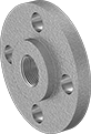
Low-Pressure Steel Threaded Pipe Flanges
Use these flanges for low-pressure applications in noncorrosive environments. Bolt two flanges of the same size together with a gasket (sold separately) to create an access point within a line.
Reducing flanges allow you to transition your system to a smaller pipe size; attach to a flange with a larger pipe size but with the same flange dimensions.
![]() For technical drawings and 3-D models, click on a part number.
For technical drawings and 3-D models, click on a part number.


- For Use With: Air, Natural Gas, Oil, Steam, Water
- Pressure Class: 150
- Specifications Met:
NPT: ASME B16.5, ASTM A105, MSS SP-25
BSPT: ASTM A105 - Fittings: Use Class 125 or 150 iron and steel
- Pipe Nipples and Pipe: Use Schedule 40 steel


- For Use With:
1/4 Pipe Size: Air, Natural Gas, Oil, Water
All other sizes: Air, Natural Gas, Oil, Steam, Water - Specifications Met:
1/4 Pipe Size: ASTM A105, MSS SP-6
All other sizes: ASME B16.5, ASTM A105, MSS SP-25, MSS SP-6 - Fittings: Use Class 125 or 150 iron and steel
- Pipe Nipples and Pipe: Use Schedule 40 Steel
Bolt Hole | |||||||||||
|---|---|---|---|---|---|---|---|---|---|---|---|
| Pipe Size | For Flange Pipe Size | Flange OD | For Bolt Dia. | Dia. | No. of | Bolt Circle Dia. | Max. Pressure | Max. Steam Pressure | Material | Each | |
NPT | |||||||||||
| 2 | 6 | 11" | 3/4" | 7/8" | 8 | 9 1/2" | 285 psi @ 72° F | 230 psi @ 300° F | Steel | 00000000 | 0000000 |
| 3 | 6 | 11" | 3/4" | 7/8" | 8 | 9 1/2" | 285 psi @ 72° F | 230 psi @ 300° F | Steel | 00000000 | 000000 |
| 4 | 6 | 11" | 3/4" | 7/8" | 8 | 9 1/2" | 285 psi @ 72° F | 230 psi @ 300° F | Steel | 0000000 | 000000 |
| 5 | 6 | 11" | 3/4" | 7/8" | 8 | 9 1/2" | 285 psi @ 72° F | 230 psi @ 300° F | Steel | 0000000 | 000000 |
Low-Pressure Steel Threaded Pipe Flanges for Low Temperatures


- For Use With: Air, Natural Gas, Oil, Steam, Water
- Pressure Class: 150
- Temperature Range: -40° to 800° F
- Specifications Met: ASME B16.5, ASTM A350, MSS SP-25
- Certification: Material Certificate with Traceable Lot Number and Test Report
- Fittings: Use Schedule 40 ASTM A420 carbon steel
- Pipe Nipples and Pipe: Use Schedule 40 ASTM A333 carbon steel
Use these Pressure Class 150 pipe flanges in low-pressure lines where temperatures drop down to -40° F. Even as temperatures drop, these flanges won't become brittle, so they absorb impact better than our other low-pressure steel flanges. All have been impact tested to verify their toughness. Bolt two flanges together with a gasket to create an access point within a line. With threaded connections, you can take them apart for maintenance and repairs.
![]() For technical drawings and 3-D models, click on a part number.
For technical drawings and 3-D models, click on a part number.
Bolt Hole | ||||||||||
|---|---|---|---|---|---|---|---|---|---|---|
| Pipe Size | Flange OD | For Bolt Dia. | Dia. | No. of | Bolt Circle Dia. | Max. Pressure | Max. Steam Pressure | Material | Each | |
NPT | ||||||||||
| 6 | 11" | 3/4" | 7/8" | 8 | 9 1/2" | 285 psi @ 72° F | 230 psi @ 300° F | A350 LF2 Steel | 0000000 | 0000000 |
FM-Approved Low-Pressure Cast Iron Threaded Pipe Flanges
Suitable for use in fire-protection applications, these flanges are brittle and can be quickly opened with the strike of a sledge hammer. Bolt two flanges of the same size together with a gasket (sold separately) to create an access point within a line. Use in noncorrosive environments.
Reducing flanges transition your system to a smaller pipe size. Attach them to a flange with a larger pipe size but with the same flange dimensions.
![]() For technical drawings and 3-D models, click on a part number.
For technical drawings and 3-D models, click on a part number.


- For Use With: Air, Natural Gas, Oil, Steam, Water
- Specifications Met:
3/4 Pipe Size: ASME B1.20.1, ASME B16.1, ASTM A126, FM Approved
All other sizes: ASME B1.20.1, ASME B16.1, ASTM A126, FM Approved, UL Listed - Pipe Nipples and Pipe: Use Schedule 40 steel
- Fittings: Use Class 125 iron and steel
Bolt Hole | ||||||||||
|---|---|---|---|---|---|---|---|---|---|---|
| Pipe Size | Flange OD | For Bolt Dia. | Dia. | No. of | Bolt Circle Dia. | Max. Pressure | Max. Steam Pressure | Material | Each | |
NPT | ||||||||||
| 6 | 11" | 3/4" | 7/8" | 8 | 9 1/2" | 125 psi @ 72° F | 125 psi @ 350° F | Iron | 000000000 | 0000000 |


- For Use With: Air, Natural Gas, Oil, Steam, Water
- Specifications Met: ASME B1.20.1, ASME B16.1, ASTM A126, ASTM A153, FM Approved
- Pipe Nipples and Pipe: Use Schedule 40 iron and steel
- Fittings: Use Class 125 iron and steel
Bolt Hole | |||||||||||
|---|---|---|---|---|---|---|---|---|---|---|---|
| Pipe Size | For Flange Pipe Size | Flange OD | For Bolt Dia. | Dia. | No. of | Bolt Circle Dia. | Max. Pressure | Max. Steam Pressure | Material | Each | |
NPT | |||||||||||
| 4 | 6 | 11" | 3/4" | 7/8" | 8 | 9 1/2" | 175 psi @ 72° F | 125 psi @ 350° F | Iron | 000000000 | 0000000 |
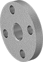
Low-Pressure Galvanized Steel Threaded Pipe Flanges


- For Use With: Air, Natural Gas, Oil, Steam, Water
- Pressure Class: 150
- Specifications Met: ASTM A123, ASTM A105, ASME B16.5
- Pipe Nipples and Pipe: Use Schedule 40 galvanized steel
- Fittings: Use Class 125 or 150 galvanized iron and galvanized steel
The galvanized finish on these flanges provides fair corrosion resistance. Also known as Pressure Class 150 flanges, they are for use in low-pressure applications. Bolt two same-size flanges together with a gasket (sold separately) to create an access point within a line.
![]() For technical drawings and 3-D models, click on a part number.
For technical drawings and 3-D models, click on a part number.
Bolt Hole | |||||||||
|---|---|---|---|---|---|---|---|---|---|
| Pipe Size | Flange OD | For Bolt Dia. | Dia. | No. of | Bolt Circle Dia. | Max. Pressure | Max. Steam Pressure | Each | |
NPT | |||||||||
| 6 | 11" | 3/4" | 7/8" | 8 | 9 1/2" | 285 psi @ 72° F | 150 psi @ 300° F | 00000000 | 0000000 |
Medium-Pressure Steel Threaded Pipe Flanges


- For Use With: Air, Natural Gas, Oil, Steam, Water
- Pressure Class: See table
- Specifications Met: ASTM A105, ASME B16.5
- Pipe Nipples and Pipe: Use Schedule 80 steel
- Fittings: Use Class 300 or Schedule 80 iron and steel
With better strength than our low-pressure steel flanges, these are for use in medium-pressure applications. Bolt two same-size flanges together with a gasket (sold separately) to create an access point within a line. Flanges are also known as Pressure Class 300 or Pressure Class 600 flanges. Use in noncorrosive environments.
![]() For technical drawings and 3-D models, click on a part number.
For technical drawings and 3-D models, click on a part number.
Bolt Hole | ||||||||||
|---|---|---|---|---|---|---|---|---|---|---|
| Pipe Size | Flange OD | For Bolt Dia. | Dia. | No. of | Bolt Circle Dia. | Max. Pressure | Max. Steam Pressure | Material | Each | |
NPT | ||||||||||
Pressure Class 300 | ||||||||||
| 5 | 11" | 3/4" | 7/8" | 8 | 9 1/4" | 600 psi @ 72° F | 300 psi @ 300° F | Steel | 00000000 | 0000000 |
Aluminum Unthreaded Pipe Flanges
Also known as Pressure Class 125 flanges, these are for use in low-pressure applications. Bolt two same-size flanges together with a gasket (sold separately) to create an access point within a line. Flanges are aluminum, which is lightweight with good corrosion resistance.
Butt-weld flanges are also known as weld-neck flanges; the flange neck has a beveled end that, when flush to pipe, creates a trough for a strong weld. Slip-on weld flanges have no internal stop; slide a pipe through the flange and weld on both sides. Cap flanges are also known as blind flanges.
![]() For technical drawings and 3-D models, click on a part number.
For technical drawings and 3-D models, click on a part number.
- For Use With: Air, Oil, Water
- Pressure Class: 125
- Specifications Met: ASME B16.1
- Fittings: Use Schedule 40 aluminum
- Pipe: Use Schedule 40 aluminum
Bolt Hole | ||||||||
|---|---|---|---|---|---|---|---|---|
| Pipe Size | Flange OD | For Bolt Dia. | Dia. | No. of | Bolt Circle Dia. | Max. Pressure | Each | |
| 6 | 11" | 3/4" | 7/8" | 8 | 9 1/2" | 150 psi @ 72° F | 000000000 | 0000000 |
Low-Pressure Aluminum Threaded Pipe Flanges
Also known as Pressure Class 125 flanges, these are for use in low-pressure applications. Bolt two same-size flanges together with a gasket (sold separately) to create an access point within a line. Flanges are aluminum, which is lightweight with good corrosion resistance.
Reducing flanges allow you to transition your system to a smaller pipe size; attach to a flange with a larger pipe size but with the same flange dimensions.
![]() For technical drawings and 3-D models, click on a part number.
For technical drawings and 3-D models, click on a part number.

- For Use With: Air, Oil, Water
- Pressure Class: 125
- Specifications Met:
Pipe Size 1-6: ASME B16.1 - Fittings: Use Class 150 aluminum
- Pipe Nipples and Pipe: Use Schedule 40 aluminum
Bolt Hole | ||||||||
|---|---|---|---|---|---|---|---|---|
| Pipe Size | Flange OD | For Bolt Dia. | Dia. | No. of | Bolt Circle Dia. | Max. Pressure | Each | |
NPT | ||||||||
| 6 | 11" | 3/4" | 7/8" | 8 | 9 1/2" | 150 psi @ 72° F | 000000000 | 0000000 |

- For Use With: Air, Oil, Water
- Pressure Class: 125
- Specifications Met: ASME B16.1
- Fittings: Use Class 150 aluminum
- Pipe Nipples and Pipe: Use Schedule 40 aluminum
Bolt Hole | |||||||||
|---|---|---|---|---|---|---|---|---|---|
| Pipe Size | For Flange Pipe Size | Flange OD | For Bolt Dia. | Dia. | No. of | Bolt Circle Dia. | Max. Pressure | Each | |
NPT | |||||||||
| 4 | 6 | 11" | 3/4" | 7/8" | 8 | 9 1/2" | 150 psi @ 72° F | 000000000 | 0000000 |
Thick-Wall Plastic Pipe Flanges for Water
- For Use With: Drinking Water, Water
- Pressure Class: 150
- Maximum Temperature: 140° F
- Specifications Met: ASTM D1784, NSF/ANSI 61
- Pipe Nipples and Pipe: Use Schedule 80 PVC Plastic
- Fittings: Use Schedule 80 PVC Plastic
Also known as Pressure Class 150 flanges, these flanges have thick, strong walls to handle heavy duty industrial plumbing and water supply applications, such as water processing, waste water treatment, and irrigation. They meet NSF/ANSI 61 for drinking water. Bolt two same-size flanges together with a gasket (sold separately) to create an access point within a line. All are PVC, which has good corrosion resistance. They meet ASTM D1784 specifications and testing requirements for material quality.
Warning: Never use plastic pipe flanges and pipe with compressed air or gas.
Sealants cannot be sold to Colorado, Connecticut, District of Columbia, Delaware, Illinois, Indiana, Massachusetts, Maryland, Maine, Michigan, New Hampshire, New Jersey, Northern Virginia, New York, Ohio, Pennsylvania, Rhode Island, or Utah due to local VOC (Volatile Organic Compounds) regulations.
![]() For technical drawings and 3-D models, click on a part number.
For technical drawings and 3-D models, click on a part number.


Attach socket-connect ends to unthreaded pipe or another socket-connect fitting with a PVC primer and cement (also known as solvent weld).


Attach socket-connect ends to unthreaded pipe or another socket-connect fitting with a PVC primer and cement (also known as solvent weld).
Rotating flanges are also known as Van Stone flanges; they swivel for easy bolt hole alignment.


Attach socket-connect ends to unthreaded pipe or another socket-connect fitting with a PVC primer and cement (also known as solvent weld).
Rotating flanges are also known as Van Stone flanges; they swivel for easy bolt hole alignment.


To prevent leaks in threaded connections, apply a sealant to the male threads. For plastic threads, apply a non-hardening, plastic-compatible sealant. Tape or sealants with PTFE are not recommended for plastic-to-plastic connections.

Cap flanges are also known as blind flanges.
Bolt Hole | |||||||||
|---|---|---|---|---|---|---|---|---|---|
| Pipe Size | Flange OD | For Bolt Dia. | Dia. | No. | Bolt Circle Dia. | Material | Color | Each | |
| 6 | 11" | 3/4" | 7/8" | 8 | 9 1/2" | PVC Plastic | Dark Gray | 00000000 | 0000000 |
CPVC Pipe Flanges for Hot Water
- For Use With: Acetic Acid (10%), Calcium Chloride, Deionized Water, Drinking Water, Hydrochloric Acid (25%), Phosphoric Acid (85%), Salt Water, Sulfuric Acid (75%), Water,
Fixed Cap Flanges: Acetic Acid (10%), Calcium Chloride, Deionized Water, Drinking Water, Hydrochloric Acid (25%), Nitric Acid (10%), Phosphoric Acid (85%), Salt Water, Sulfuric Acid (75%), Water - Pressure Class: 150
- Maximum Temperature: 200° F
- Specifications Met: ASTM D1784, NSF/ANSI 61
- Pipe Nipples and Pipe: Use Schedule 80 CPVC Plastic
- Fittings: Use Schedule 80 CPVC Plastic
Made of CPVC, these flanges can handle high temperatures up to 200° F. They meet NSF/ANSI Standard 61 for drinking water. Bolt two same-size flanges together with a gasket (sold separately) to create an access point within a line. Also known as Pressure Class 150 flanges, they have thick, strong walls to handle heavy duty industrial plumbing and water supply applications, such as water processing and waste water treatment. Flanges have good corrosion resistance. They meet ASTM D1784 specifications and testing requirements for material quality. They are comparable to Corzan.
Warning: Never use plastic pipe flanges and pipe with compressed air or gas.
Sealants cannot be sold to Colorado, Connecticut, District of Columbia, Delaware, Illinois, Indiana, Massachusetts, Maryland, Maine, Michigan, New Hampshire, New Jersey, Northern Virginia, New York, Ohio, Pennsylvania, Rhode Island, or Utah due to local regulatory limits on VOCs (Volatile Organic Compounds).
![]() For technical drawings and 3-D models, click on a part number.
For technical drawings and 3-D models, click on a part number.

Attach socket-connect ends to unthreaded pipe or another socket-connect fitting with a CPVC primer and cement (also known as solvent weld).
Attach socket-connect ends to unthreaded pipe or another socket-connect fitting with a CPVC primer and cement (also known as solvent weld).
Rotating flanges are also known as Van Stone flanges; they swivel for easy bolt hole alignment.
Attach socket-connect ends to unthreaded pipe or another socket-connect fitting with a CPVC primer and cement (also known as solvent weld).
Rotating flanges are also known as Van Stone flanges; they swivel for easy bolt hole alignment.
Cap flanges are also known as blind flanges.
Bolt Hole | ||||||||
|---|---|---|---|---|---|---|---|---|
| Pipe Size | Flange OD | For Bolt Dia. | Dia. | No. of | Bolt Circle Dia. | Color | Each | |
| 6 | 11" | 3/4" | 7/8" | 8 | 9 1/2" | Light Gray | 00000000 | 0000000 |
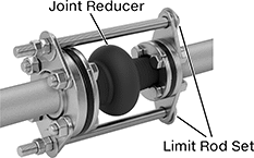
Expansion Joints with Flanged Ends


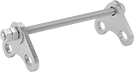
These joints reduce stress, vibration, and noise in piping systems by providing a point of flexibility to absorb movement. The flanged ends rotate for easy bolt hole alignment during installation. They mate with a same-size flat-surface Class 150 flange without the need for a gasket. Joints have a flexible body that is reinforced with nylon for added strength.
Position the expansion joints as close as possible to anchor points. Attach limit rod sets (sold separately) to the flanges to prevent overextension where anchoring is insufficient. To accommodate the thickness of the limit rod mounting plate, use bolts that are 7/8" longer than the bolts connecting the expansion joint to the pipe flange. Each set of limit rods requires eight bolts (not included).
![]() For technical drawings and 3-D models, click on a part number.
For technical drawings and 3-D models, click on a part number.
- For Use With: Nonabrasive Slurry, Water
- Temperature Range: -10° to 220° F
- Maximum Pressure: 220 psi @ 72° F
- Maximum Vacuum: 26 in. of Hg @ 72° F
- For Use With: Alcohol, Water
- Temperature Range: -20° to 250° F
- Maximum Pressure: 220 psi @ 72° F
- Maximum Vacuum: 26 in. of Hg @ 72° F
High-Temperature All-Metal Expansion Joints with Flanged Ends

- For Use With: Air, Natural Gas, Oil, Steam, Water
- Temperature Range: -20° to 800° F
- Maximum Pressure: 150 psi @ 72° F
- Maximum Vacuum: 29 in. of Hg @ 72° F
These all-metal expansion joints can handle higher temperatures than rubber expansion joints. They reduce stress, vibration, and noise in piping systems by providing a point of flexibility to absorb movement. Joints are made of 304 stainless steel for very good corrosion resistance. The flanged ends rotate for easy bolt hole alignment during installation. Flanges mate with a same-size flat-surface Class 150 flange with a gasket (sold separately).
Liners (sold separately) slide into the expansion joint to provide a smooth interior for unrestricted flow.
![]() For technical drawings and 3-D models, click on a part number.
For technical drawings and 3-D models, click on a part number.
Chemical-Resistant Expansion Joints with Flanged Ends

- For Use With: Coolant, Hydrochloric Acid, Water
- Temperature Range: -0° to 400° F
- Maximum Pressure: See table
- Maximum Vacuum: 29 in. of Hg @ 72° F
The PTFE body on these expansion joints has a super-smooth surface that stands up to corrosive chemicals. Joints have a triple-bulb design that provides excellent vibration absorption, reducing stress on your piping system. The flanges mate with a same-size flat-surface Class 150 flange without the need for a gasket. Limit rods are attached to the flanges to prevent overextension.
![]() For technical drawings and 3-D models, click on a part number.
For technical drawings and 3-D models, click on a part number.
Distance | Threaded Bolt Holes | |||||||||||
|---|---|---|---|---|---|---|---|---|---|---|---|---|
| Flange OD | Pipe Size | Lg. | No. of Bolt Holes | Compression | Expansion | Offset | Max. Pressure | Expansion Joint Type | Flange Material | Bolt Hole Thread Size | Each | |
Ultra-Corrosion-Resistant Coated PTFE Plastic | ||||||||||||
| 11" | 6 | 4" | 8 | 1 1/8" | 1 1/8" | 9/16" | 130 psi @ 72° F | Triple Bulb | Iron | 3/4"-10 | 0000000 | 000000000 |
Expansion Joints with Sealing Flanged Ends for Metal Pipe


Because the flanges are molded into the body for a wide sealing surface, these joints provide a tighter seal than other expansion joints. Each flange is supported by a zinc-plated steel plate. Flanges mate with a same-size flat-surface Class 150 flange without the need for a gasket. Joints reduce stress, vibration, and noise in metal piping systems by providing a point of flexibility to absorb movement. They have a flexible body that is reinforced with cord for added strength.
Mount these expansion joints as close as possible to anchor points. Attach limit rod sets (sold separately) to the flanges to prevent overextension where anchoring is insufficient. To accommodate the thickness of the limit rod mounting plate, use bolts that are 7/8" longer than the bolts connecting the expansion joint to the pipe flange. Each set of limit rods requires eight bolts (not included).
![]() For technical drawings and 3-D models, click on a part number.
For technical drawings and 3-D models, click on a part number.
- For Use With: Coolant, Grease, Hydraulic Fluid, Water
- Temperature Range: -65° to 220° F
- Maximum Pressure: 210 psi @ 72° F
- Maximum Vacuum: 29 in. of Hg @ 72° F
- For Use With: Grain Alcohol, Nonabrasive Slurry, Water
- Temperature Range: -20° to 220° F
- Maximum Pressure: 190 psi @ 72° F
- Maximum Vacuum: 26 in. of Hg @ 72° F
Expansion Joints with Sealing Flanged Ends for Plastic Pipe


These joints reduce stress, vibration, and noise in plastic piping systems by providing a point of flexibility to absorb movement. Joints provide a tighter seal than other expansion joints because the flanges are molded into the body for a wide sealing surface. Each flange is supported by a zinc-plated steel plate. Flanges mate with a same-size flat-surface Class 150 flange without the need for a gasket.
Neoprene joints resist abrasion better than EPDM joints.
Position the expansion joints as close as possible to anchor points. Attach limit rod sets (sold separately) to the flanges to prevent overextension where anchoring is insufficient. To accommodate the thickness of the limit rod mounting plate, use bolts that are 7/8" longer than the bolts connecting the expansion joint to the pipe flange. Each set of limit rods requires eight bolts (not included).
![]() For technical drawings and 3-D models, click on a part number.
For technical drawings and 3-D models, click on a part number.
- For Use With: Natural Gas, Oil, Water
- Temperature Range: -10° to 220° F
- Maximum Pressure: See table
- Maximum Vacuum: 24 in. of Hg @ 72° F
- For Use With: Alcohol, Water
- Temperature Range: -20° to 250° F
- Maximum Pressure: 220 psi @ 72° F
- Maximum Vacuum: 24 in. of Hg @ 72° F
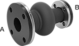
Expansion Joint Reducers with Flanged Ends
Connect different pipe sizes in your line while adding a point of flexibility between them. These expansion joints absorb movement between two connected pipes to reduce stress, vibration, and noise. Their flanged ends mate with same-size Class 150 flanges without the need for a gasket. Each flange is supported by a zinc-plated steel plate. The body of these expansion joints is reinforced with cord for added strength.
Your pipe system must be rigidly anchored on both sides of the expansion joint to control expansion or contraction of the line. When proper anchoring cannot be provided, limit rods (sold separately) are required.
![]() For technical drawings and 3-D models, click on a part number.
For technical drawings and 3-D models, click on a part number.
- For Use With: Air, Alcohol, Calcium Chloride, Coolant, Grain Alcohol, Grease, Hydraulic Fluid, Sodium Carbonate (20% in Water), Water
- Temperature Range: -20° to 250° F
- Maximum Pressure: See Table
- Maximum Vacuum: 26 in. of Hg @ 72° F
Unthreaded Bolt Holes | ||||||||||||||||
|---|---|---|---|---|---|---|---|---|---|---|---|---|---|---|---|---|
Flange OD | Pipe Size | No. of Bolt Holes | Distance | Bolt Hole Size | ||||||||||||
(A) | (B) | (A) | (B) | Lg. | (A) | (B) | Compression | Expansion | Offset | Max. Pressure | Expansion Joint Type | Flange Material | (A) | (B) | Each | |
EPDM Rubber | ||||||||||||||||
| 11" | 9" | 6 | 4 | 8" | 8 | 8 | 1 9/16" | 3/4" | 1/2" | 190 psi @ 72° F | Single Bulb | EPDM Rubber | 7/8" | 3/4" | 0000000 | 000000000 |
| 13 1/2" | 11" | 8 | 6 | 8" | 8 | 8 | 1 9/16" | 3/4" | 1/2" | 190 psi @ 72° F | Single Bulb | EPDM Rubber | 7/8" | 7/8" | 0000000 | 00000000 |

Expansion Joints with Flanged Ends for High Vibration


These expansion joints have a double-bulb design for extra movement and vibration absorption. The flanged ends rotate for easy bolt hole alignment during installation. They mate with a same-size flat-surface Class 150 flange without the need for a gasket. Joints have a flexible body that is reinforced with nylon for added strength.
Attach limit rod sets (sold separately) to the flanges to prevent overextension where anchoring is insufficient. To accommodate the thickness of the limit rod mounting plate, use bolts that are 7/8" longer than the bolts connecting the expansion joint to the pipe flange. Each set of limit rods requires eight bolts (not included).
![]() For technical drawings and 3-D models, click on a part number.
For technical drawings and 3-D models, click on a part number.
- For Use With: Grain Alcohol, Nonabrasive Slurry, Water
- Temperature Range: -10° to 220° F
- Maximum Pressure: 220 psi @ 72° F
- Maximum Vacuum: 26 in. of Hg @ 72° F
- For Use With: Alcohol, Water
- Temperature Range: -20° to 250° F
- Maximum Pressure: 220 psi @ 72° F
- Maximum Vacuum: 26 in. of Hg @ 72° F
Expansion Joints with Flanged Ends for Drinking Water


- For Use With: Drinking Water
- Temperature Range: -20° to 250° F
- Maximum Pressure: See table
- Maximum Vacuum: 26in. of Hg @ 72° F
- Specifications Met: NSF/ANSI 61
The EPDM lining in these joints meets NSF/ANSI 61 standard for use with drinking water. To reduce stress, vibration, and noise in piping systems, they provide a point of flexibility to absorb movement. These joints have a flexible body reinforced with polyester cord for added strength. A zinc-plated steel plate supports each flange. The flanges mate with the same-size flat-surface Class 150 flange without the need for a gasket.
Position the expansion joints as close as possible to anchor points. Attach limit rod sets (sold separately) to the flanges to prevent overextension where anchoring is insufficient. To accommodate the thickness of the limit rod mounting plate, use bolts that are 7/8" longer than the bolts connecting the expansion joint to the pipe flange. Each set of limit rods requires eight bolts (not included).
![]() For technical drawings and 3-D models, click on a part number.
For technical drawings and 3-D models, click on a part number.
Expansion Joints | ||||||||||||||
|---|---|---|---|---|---|---|---|---|---|---|---|---|---|---|
Distance | Limit Rod Sets | |||||||||||||
| Flange OD | Pipe Size | Lg. | No. of Bolt Holes | Compression | Expansion | Offset | Max. Pressure | Expansion Joint Type | Flange Material | Bolt Hole Size | Each | Pair | ||
EPDM Rubber with EPDM Rubber Liner | ||||||||||||||
| 11" | 6 | 6" | 8 | 1 5/8" | 3/4" | 3/4" | 190 psi @ 72° F | Single Bulb | Zinc-Plated Steel | 7/8" | 0000000 | 000000000 | 0000000 | 0000000 |
Metal Cam-and-Groove Hose Couplings for Chemicals and Petroleum

Made of metal, these couplings have better durability than plastic cam-and-groove couplings. A complete coupling consists of a plug and a socket (both sold separately) that allow you to quickly connect and disconnect medium-to large-diameter hose lines. To connect, insert the plug into the socket and press the levers down. The levers fit snugly into the groove on the plug’s body and force the plug against the gasket to form a tight seal. To disconnect, lift both levers and pull out the plug. Couplings are compatible with Andrews, Dixon, Ever-Tite, and PT cam-and-groove couplings.
Plugs with flanged end are also known as PFA adapters. Bolt the flanged end to another same-size flange with a gasket (sold separately).
Sockets with flanged end are also known as PFC couplers. Bolt the flanged end to another same-size flange with a gasket (sold separately).
Aluminum plugs and sockets are lighter in weight than 316 stainless steel plugs and sockets. They have good corrosion resistance. 316 stainless steel plugs and sockets have excellent corrosion resistance.
Note: To ensure a correct fit, make sure that the plug and socket have the same coupling size.
Warning: Relieve all pressure before disconnecting the couplings. Do not use cam-and-groove couplings with compressed air or gas.
![]() For technical drawings and 3-D models, click on a part number.
For technical drawings and 3-D models, click on a part number.

- For Use With: Citric Acid, Diesel Fuel, Gasoline, Hydraulic Fluid
- Maximum Pressure: See table
- Temperature Range: -65° to 250° F
- Compatible With: Andrews Cam-and-Groove, Dixon Cam-and-Groove, Ever-Tite Cam-and-Groove, PT Coupling Cam-and-Groove
- Specifications Met:
Aluminum: ASME B16.24, Fed. Spec. A-A-59326
316 Stainless Steel: ASME B16.5, Fed. Spec. A-A-59326
Bolt Hole | |||||||||||||
|---|---|---|---|---|---|---|---|---|---|---|---|---|---|
| Coupling Size | Plug OD | Pipe Size | Dash Size | Flange OD | Flanged Connection Surface | Pressure Class | Max. Pressure | For Bolt Dia. | Dia. | No. of | Bolt Circle Dia. | Each | |
Aluminum | |||||||||||||
| 6 | 6 15/16" | 6 | 96 | 11" | Flat | 150 | 75 psi @ 72° F | 3/4" | 7/8" | 8 | 9 1/2" | 000000000 | 0000000 |
316 Stainless Steel | |||||||||||||
| 6 | 6 15/16" | 6 | 96 | 11" | Flat | 150 | 75 psi @ 72° F | 3/4" | 7/8" | 8 | 9 1/2" | 000000000 | 000000 |

- For Use With: Citric Acid, Diesel Fuel, Gasoline, Hydraulic Fluid
- Maximum Pressure: See table
- Temperature Range: -65° to 250° F
- Compatible With: Andrews Cam-and-Groove, Dixon Cam-and-Groove, Ever-Tite Cam-and-Groove, PT Coupling Cam-and-Groove
- Specifications Met:
Aluminum: ASME B16.24, Fed. Spec. A-A-59326
316 Stainless Steel: ASME B16.5, Fed. Spec. A-A-59326
Sockets | ||||||||||||||||||
|---|---|---|---|---|---|---|---|---|---|---|---|---|---|---|---|---|---|---|
Bolt Hole | Replacement Gaskets | Replacement Levers | ||||||||||||||||
| Coupling Size | Socket ID | Pipe Size | Dash Size | Flange OD | Pressure Class | No. of Levers | Max. Pressure | For Bolt Dia. | Dia. | No. of | Bolt Circle Dia. | Each | Pkg. Qty. | Pkg. | Each | |||
Aluminum with Brass Levers and Zinc-Plated Steel Pull Rings | ||||||||||||||||||
Flat Flanged Connection Surface | ||||||||||||||||||
| 6 | 6 15/16" | 6 | 96 | 11" | 150 | 2 | 75 psi @ 72° F | 3/4" | 7/8" | 8 | 9 1/2" | 000000000 | 0000000 | 5 | 0000000 | 000000 | 000000000 | 000000 |
316 Stainless Steel with 316 Stainless Steel Levers and 304 Stainless Steel Pull Rings | ||||||||||||||||||
Raised Flanged Connection Surface | ||||||||||||||||||
| 6 | 6 15/16" | 6 | 96 | 11" | 150 | 2 | 75 psi @ 72° F | 3/4" | 7/8" | 8 | 9 1/2" | 000000000 | 00000000 | 5 | 0000000 | 00000 | 000000000 | 00000 |
Metal Cam-and-Groove Hose Couplings for Water

A complete coupling consists of a plug and a socket (both sold separately) that allow you to quickly connect and disconnect medium-to large-diameter hose lines. To connect, insert the plug into the socket and press the levers down. The levers fit snugly into the groove on the plug’s body and force the plug against the gasket to form a tight seal. To disconnect, lift both levers and pull out the plug.
Plugs with flanged end are also known as PFA adapters. Bolt the flanged end to another same-size flange with a gasket (sold separately).
Aluminum couplings are lighter in weight than brass plugs and sockets. They have good abrasion and corrosion resistance. Note: To ensure a correct fit, make sure that the plug and socket have the same coupling size.
Warning: Relieve all pressure before disconnecting the couplings. Do not use cam-and-groove couplings with compressed air or gas.
![]() For technical drawings and 3-D models, click on a part number.
For technical drawings and 3-D models, click on a part number.

- Maximum Pressure: See table
- Temperature Range: -65° to 250° F
- Specifications Met: ASME B16.5, Fed. Spec. A-A-59326
- Compatible With: Andrews Cam-and-Groove Couplings, Dixon Cam-and-Groove Couplings, Ever-Tite Cam-and-Groove Couplings, PT Coupling Cam-and-Groove Couplings
Bolt Holes | ||||||||||||
|---|---|---|---|---|---|---|---|---|---|---|---|---|
| Coupling Size | Plug OD | Pipe Size | Flange OD | Flanged Connection Surface | Pressure Class | Max. Pressure | For Bolt Dia. | Dia. | No. of | Bolt Circle Dia. | Each | |
Anodized Aluminum | ||||||||||||
| 6 | 6 15/16" | 6 | 11" | Flat | 150 | 75 psi @ 72° F | 3/4" | 7/8" | 8 | 9 1/2" | 00000000 | 0000000 |