


Filter by
Clutch Type
Maximum Torque
Drive Type
For Shaft Misalignment Type
Torque
Shaft Mount Type
Rotation Speed
OD
Overall Length

Maximum Rotation Speed
Export Control Classification Number (ECCN)

DFARS Specialty Metals
Soft-Start Centrifugal Clutches
Disengaged until they rotate fast enough to transmit torque, these clutches give the components on your driven side a smooth start by allowing the driving side to start without load.
Friction Engagement
 |  |
Shaft-to-Shaft with Engagement Springs | Shaft-to-Shaft with Support Rollers |
 | |
Through Shaft with Support Rollers and Pulley |
Shaft-to-Shaft—Shaft-to-shaft clutches also act as a shaft coupling, allowing you to regulate torque transmission between two shafts.
Through Shaft—Through-shaft clutches regulate torque transmission between an input shaft and a mounted component.
Support Rollers—Clutches with support rollers are quieter and last longer than other centrifugal clutches because the contact points are supported by urethane rollers to prevent slipping.
With Pulley—Clutches with a pulley come ready to install a V-belt.
Set-Screw Shaft Mount—Clutches that mount to shafts with set screws bite into your shaft when tightened to hold it.
Clutch Engagement Springs—Clutch engagement springs allow you to change the speed at which the clutch engages.
Misalignment Capability | Clockwise-and-Counterclockwise Drive | ||||||||||||||||||||||||||||||||||||||||||||||||||||||||||||||||||||||||||||||||||||||||||||||||||
|---|---|---|---|---|---|---|---|---|---|---|---|---|---|---|---|---|---|---|---|---|---|---|---|---|---|---|---|---|---|---|---|---|---|---|---|---|---|---|---|---|---|---|---|---|---|---|---|---|---|---|---|---|---|---|---|---|---|---|---|---|---|---|---|---|---|---|---|---|---|---|---|---|---|---|---|---|---|---|---|---|---|---|---|---|---|---|---|---|---|---|---|---|---|---|---|---|---|---|---|
For Shaft Dia. | For Shaft Type | Engagement Speed, rpm | Max. Power, hp | Max. Rotation Speed, rpm | Pitch Dia. | For Belt Trade Size | Parallel | Angular | OD | Overall Lg. | Keyway Wd. × Keyway Dp. | Material | Shaft Mount Type | Each | |||||||||||||||||||||||||||||||||||||||||||||||||||||||||||||||||||||||||||||||||||||
Shaft-to-Shaft with Engagement Springs | |||||||||||||||||||||||||||||||||||||||||||||||||||||||||||||||||||||||||||||||||||||||||||||||||||
| 5/8" | Keyed | 830 | 13 | 3,600 | — | — | 0.003" | 0.25° | 4 3/16" | 2 1/2" | 3/16" × 3/32" | Steel | Set Screw | 00000000 | 0000000 | ||||||||||||||||||||||||||||||||||||||||||||||||||||||||||||||||||||||||||||||||||||
| 3/4" | Keyed | 830 | 13 | 3,600 | — | — | 0.003" | 0.25° | 4 3/16" | 2 1/2" | 3/16" × 3/32" | Steel | Set Screw | 00000000 | 000000 | ||||||||||||||||||||||||||||||||||||||||||||||||||||||||||||||||||||||||||||||||||||
| 1" | Keyed | 830 | 13 | 3,600 | — | — | 0.003" | 0.25° | 4 3/16" | 2 1/2" | 1/4" × 1/8" | Steel | Set Screw | 00000000 | 000000 | ||||||||||||||||||||||||||||||||||||||||||||||||||||||||||||||||||||||||||||||||||||
Shaft-to-Shaft with Support Rollers | |||||||||||||||||||||||||||||||||||||||||||||||||||||||||||||||||||||||||||||||||||||||||||||||||||
| 1/2" | Round | 1,100 | 7.5 | 1,750 | — | — | — | — | 3 63/64" | 3 19/64" | — | Steel | Set Screw | 00000000 | 000000 | ||||||||||||||||||||||||||||||||||||||||||||||||||||||||||||||||||||||||||||||||||||
| 5/8" | Keyed | 1,100 | 7.5 | 1,750 | — | — | — | — | 3 63/64" | 3 19/64" | 3/16" × 3/32" | Steel | Set Screw | 00000000 | 000000 | ||||||||||||||||||||||||||||||||||||||||||||||||||||||||||||||||||||||||||||||||||||
| 3/4" | Keyed | 1,100 | 7.5 | 1,750 | — | — | — | — | 3 63/64" | 3 19/64" | 3/16" × 3/32" | Steel | Set Screw | 00000000 | 000000 | ||||||||||||||||||||||||||||||||||||||||||||||||||||||||||||||||||||||||||||||||||||
| 1" | Keyed | 1,100 | 7.5 | 1,750 | — | — | — | — | 3 63/64" | 3 17/64" | 1/4" × 1/8" | Steel | Set Screw | 00000000 | 000000 | ||||||||||||||||||||||||||||||||||||||||||||||||||||||||||||||||||||||||||||||||||||
Through Shaft with Support Rollers and Pulley | |||||||||||||||||||||||||||||||||||||||||||||||||||||||||||||||||||||||||||||||||||||||||||||||||||
| 5/8" | Keyed | 1,100 | 7.5 | 1,750 | 2.8" | 4L, A | — | — | 3 63/64" | 1 7/8" | 3/16" × 3/32" | Steel | Set Screw | 00000000 | 000000 | ||||||||||||||||||||||||||||||||||||||||||||||||||||||||||||||||||||||||||||||||||||
| 5/8" | Keyed | 1,100 | 7.5 | 1,750 | 3.3" | 4L, A | — | — | 3 63/64" | 1 7/8" | 3/16" × 3/32" | Steel | Set Screw | 00000000 | 000000 | ||||||||||||||||||||||||||||||||||||||||||||||||||||||||||||||||||||||||||||||||||||
| 3/4" | Keyed | 1,100 | 7.5 | 1,750 | 2.8" | 4L, A | — | — | 3 63/64" | 1 7/8" | 3/16" × 3/32" | Steel | Set Screw | 00000000 | 000000 | ||||||||||||||||||||||||||||||||||||||||||||||||||||||||||||||||||||||||||||||||||||
| 3/4" | Keyed | 1,100 | 7.5 | 1,750 | 3.3" | 4L, A | — | — | 3 63/64" | 1 7/8" | 3/16" × 3/32" | Steel | Set Screw | 00000000 | 000000 | ||||||||||||||||||||||||||||||||||||||||||||||||||||||||||||||||||||||||||||||||||||
Electric One-Way Clutches
Unlike mechanical clutches, these clutches let you electrically control when torque is transmitted. They transfer torque in one direction and spin freely in the opposite direction, so they’re useful in applications where you don’t want motion to reverse such as in backstopping, indexing, and overrunning. When you remove power from these clutches, they disengage, cutting torque to your pulley, sprocket, gear, or other mounted component without stopping your drive shaft.
Friction Engagement
 |
Through Shaft—Through-shaft clutches regulate torque transmission between an input shaft and a mounted component.
Clockwise Drive | Counterclockwise Drive | ||||||||||||||||||||||||||||||||||||||||||||||||||||||||||||||||||||||||||||||||||||||||||||||||||
|---|---|---|---|---|---|---|---|---|---|---|---|---|---|---|---|---|---|---|---|---|---|---|---|---|---|---|---|---|---|---|---|---|---|---|---|---|---|---|---|---|---|---|---|---|---|---|---|---|---|---|---|---|---|---|---|---|---|---|---|---|---|---|---|---|---|---|---|---|---|---|---|---|---|---|---|---|---|---|---|---|---|---|---|---|---|---|---|---|---|---|---|---|---|---|---|---|---|---|---|
For Shaft Dia. | For Shaft Type | Max. Torque, in·lbf | Max. Rotation Speed, rpm | OD | Overall Lg. | Electric Clutch Type | Electrical Connection Permanence | Shaft Mount Type | Wire Lead Lg. | Voltage, V DC | Current, amp | Each | Current, amp | Each | |||||||||||||||||||||||||||||||||||||||||||||||||||||||||||||||||||||||||||||||||||||
Through Shaft | |||||||||||||||||||||||||||||||||||||||||||||||||||||||||||||||||||||||||||||||||||||||||||||||||||
| 1/4" | Round | 30 | 1,400 | 1 1/4" | 1 1/8" | Power On | Hardwire | Spring Pin | 15" | 24 | 0.14 | 0000000 | 000000 | 0.24 | 0000000 | 000000 | |||||||||||||||||||||||||||||||||||||||||||||||||||||||||||||||||||||||||||||||||||
| 5/16" | Round | 30 | 1,400 | 1 1/4" | 1 1/8" | Power On | Hardwire | Spring Pin | 15" | 24 | 0.14 | 0000000 | 00000 | 0.24 | 0000000 | 00000 | |||||||||||||||||||||||||||||||||||||||||||||||||||||||||||||||||||||||||||||||||||
| 3/8" | Round | 75 | 1,400 | 1 3/4" | 1 1/2" | Power On | Hardwire | Spring Pin | 18" | 24 | 0.14 | 0000000 | 000000 | 0.24 | 0000000 | 000000 | |||||||||||||||||||||||||||||||||||||||||||||||||||||||||||||||||||||||||||||||||||
| 1/2" | Round | 75 | 1,400 | 1 3/4" | 1 1/2" | Power On | Hardwire | Spring Pin | 18" | 24 | 0.14 | 0000000 | 000000 | 0.24 | 0000000 | 000000 | |||||||||||||||||||||||||||||||||||||||||||||||||||||||||||||||||||||||||||||||||||
One-Way Clutches
Since they transfer torque in one direction and spin freely in the other, these clutches are useful in applications where you don’t want motion to reverse, such as in backstopping, indexing, and overrunning. For example, they can be used to prevent a conveyor from reversing direction.
When choosing a clutch, consider how much torque you need to transfer. You should also consider how the clutch will attach to your mounted component.
Roller Engagement—Knurled Hub
 |
Roller clutches are best for low- to medium-torque transfer in overrunning and indexing applications.
Clutches with a knurled hub can be press fit into the bore of your component.
Through Shaft—Through-shaft clutches regulate torque transmission between an input shaft and a mounted component.
Set-Screw Shaft Mount—Clutches that mount to shafts with set screws bite into your shaft when tightened to hold it.
Shaft | Hub | Clockwise Drive | Counterclockwise Drive | ||||||||||||||||||||||||||||||||||||||||||||||||||||||||||||||||||||||||||||||||||||||||||||||||
|---|---|---|---|---|---|---|---|---|---|---|---|---|---|---|---|---|---|---|---|---|---|---|---|---|---|---|---|---|---|---|---|---|---|---|---|---|---|---|---|---|---|---|---|---|---|---|---|---|---|---|---|---|---|---|---|---|---|---|---|---|---|---|---|---|---|---|---|---|---|---|---|---|---|---|---|---|---|---|---|---|---|---|---|---|---|---|---|---|---|---|---|---|---|---|---|---|---|---|---|
For Shaft Dia. | For Shaft Type | Max. Torque, ft·lbf | Max. Rotation Speed, rpm | OD | Overall Lg. | Material | Keyway Wd. × Keyway Dp. | Mount Type | Dia. | Lg. | Each | Each | |||||||||||||||||||||||||||||||||||||||||||||||||||||||||||||||||||||||||||||||||||||||
Through Shaft | |||||||||||||||||||||||||||||||||||||||||||||||||||||||||||||||||||||||||||||||||||||||||||||||||||
| 1/4" | Round | 0.83 | 5,000 | 15/16" | 31/32" | Steel | — | Set Screw | 5/8" | 9/32" | 0000000 | 0000000 | 0000000 | 0000000 | |||||||||||||||||||||||||||||||||||||||||||||||||||||||||||||||||||||||||||||||||||||
| 3/8" | Keyed | 4.16 | 5,000 | 1 3/16" | 1" | Steel | 3/32" × 3/64" | Set Screw | 9/16" | 3/8" | 0000000 | 000000 | 0000000 | 000000 | |||||||||||||||||||||||||||||||||||||||||||||||||||||||||||||||||||||||||||||||||||||
| 1/2" | Keyed | 50 | 2,000 | 1 1/2" | 1 9/32" | Steel | 1/8" × 1/16" | Set Screw | 7/8" | 1/2" | 0000000 | 000000 | 0000000 | 000000 | |||||||||||||||||||||||||||||||||||||||||||||||||||||||||||||||||||||||||||||||||||||
Roller Engagement—Keyed Hub
 |
Roller clutches are best for low- to medium-torque transfer in overrunning and indexing applications.
Clutches with a keyed hub let you slip on your component.
Through Shaft—Through-shaft clutches regulate torque transmission between an input shaft and a mounted component.
Slip-Fit Shaft Mount—Clutches that mount to shafts with a slip fit must be secured with a shaft collar or in some other way that prevents them from moving along the length of your shaft.
Shaft | Hub | Clockwise Drive | |||||||||||||||||||||||||||||||||||||||||||||||||||||||||||||||||||||||||||||||||||||||||||||||||
|---|---|---|---|---|---|---|---|---|---|---|---|---|---|---|---|---|---|---|---|---|---|---|---|---|---|---|---|---|---|---|---|---|---|---|---|---|---|---|---|---|---|---|---|---|---|---|---|---|---|---|---|---|---|---|---|---|---|---|---|---|---|---|---|---|---|---|---|---|---|---|---|---|---|---|---|---|---|---|---|---|---|---|---|---|---|---|---|---|---|---|---|---|---|---|---|---|---|---|---|
For Shaft Dia. | For Shaft Type | Max. Torque, ft·lbf | Max. Rotation Speed, rpm | OD | Overall Lg. | Material | Keyway Wd. × Keyway Dp. | Mount Type | Dia. | Lg. | Keyway Wd. × Keyway Dp. | Each | |||||||||||||||||||||||||||||||||||||||||||||||||||||||||||||||||||||||||||||||||||||||
Through Shaft | |||||||||||||||||||||||||||||||||||||||||||||||||||||||||||||||||||||||||||||||||||||||||||||||||||
| 1/4" | Keyed | 5 | 1,800 | 1 5/8" | 1 15/16" | Steel | 1/16" × 1/32" | Slip Fit | 7/8" | 13/16" | 3/16" × 3/32" | 0000000 | 0000000 | ||||||||||||||||||||||||||||||||||||||||||||||||||||||||||||||||||||||||||||||||||||||
| 3/8" | Keyed | 14 | 1,800 | 2" | 2 1/8" | Steel | 3/32" × 3/64" | Slip Fit | 1 1/4" | 1" | 3/16" × 3/32" | 0000000 | 000000 | ||||||||||||||||||||||||||||||||||||||||||||||||||||||||||||||||||||||||||||||||||||||
| 1/2" | Keyed | 14 | 1,800 | 2" | 2 1/8" | Steel | 1/8" × 1/16" | Slip Fit | 1 1/4" | 1" | 3/16" × 3/32" | 0000000 | 000000 | ||||||||||||||||||||||||||||||||||||||||||||||||||||||||||||||||||||||||||||||||||||||
| 5/8" | Keyed | 28 | 1,500 | 2 5/8" | 2 23/32" | Steel | 3/16" × 3/32" | Slip Fit | 1 3/8" | 1 5/16" | 3/16" × 3/32" | 0000000 | 000000 | ||||||||||||||||||||||||||||||||||||||||||||||||||||||||||||||||||||||||||||||||||||||
| 3/4" | Keyed | 100 | 1,000 | 3 5/8" | 3 11/32" | Steel | 3/16" × 3/32" | Slip Fit | 2 1/4" | 1 1/2" | 3/8" × 3/16" | 0000000 | 000000 | ||||||||||||||||||||||||||||||||||||||||||||||||||||||||||||||||||||||||||||||||||||||
| 1" | Keyed | 100 | 1,000 | 3 5/8" | 3 11/32" | Steel | 1/4" × 1/8" | Slip Fit | 2 1/4" | 1 1/2" | 3/8" × 3/16" | 0000000 | 000000 | ||||||||||||||||||||||||||||||||||||||||||||||||||||||||||||||||||||||||||||||||||||||
| 1 1/4" | Keyed | 100 | 1,000 | 3 5/8" | 3 11/32" | Steel | 1/4" × 1/8" | Slip Fit | 2 1/4" | 1 1/2" | 3/8" × 3/16" | 0000000 | 000000 | ||||||||||||||||||||||||||||||||||||||||||||||||||||||||||||||||||||||||||||||||||||||
| 1 1/2" | Keyed | 200 | 800 | 4 1/2" | 4 1/2" | Steel | 3/8" × 3/16" | Slip Fit | 3" | 2 1/16" | 3/8" × 3/16" | 0000000 | 000000 | ||||||||||||||||||||||||||||||||||||||||||||||||||||||||||||||||||||||||||||||||||||||
Sprag Engagement—Keyed Hub
 |
Sprag clutches handle higher torque than roller clutches because they have more contact points. This makes them best for backstopping applications.
Clutches with a keyed hub let you slip on your component.
Through Shaft—Through-shaft clutches regulate torque transmission between an input shaft and a mounted component.
Set-Screw Shaft Mount—Clutches that mount to shafts with set screws bite into your shaft when tightened to hold it.
Max. Rotation Speed, rpm | Shaft | Hub | Clockwise Drive | Counterclockwise Drive | |||||||||||||||||||||||||||||||||||||||||||||||||||||||||||||||||||||||||||||||||||||||||||||||
|---|---|---|---|---|---|---|---|---|---|---|---|---|---|---|---|---|---|---|---|---|---|---|---|---|---|---|---|---|---|---|---|---|---|---|---|---|---|---|---|---|---|---|---|---|---|---|---|---|---|---|---|---|---|---|---|---|---|---|---|---|---|---|---|---|---|---|---|---|---|---|---|---|---|---|---|---|---|---|---|---|---|---|---|---|---|---|---|---|---|---|---|---|---|---|---|---|---|---|---|
For Shaft Dia. | For Shaft Type | Max. Torque, ft·lbf | Inner-Race | Outer-Race | OD | Overall Lg. | Material | Keyway Wd. × Keyway Dp. | Mount Type | Dia. | Lg. | Keyway Wd. × Keyway Dp. | Each | Each | |||||||||||||||||||||||||||||||||||||||||||||||||||||||||||||||||||||||||||||||||||||
Through Shaft | |||||||||||||||||||||||||||||||||||||||||||||||||||||||||||||||||||||||||||||||||||||||||||||||||||
| 5/8" | Keyed | 110 | 1,950 | 900 | 2" | 2 3/4" | Steel | 3/16" × 3/32" | Set Screw | 1 1/4" | 1" | 3/16" × 3/32" | 0000000 | 000000000 | 0000000 | 000000000 | |||||||||||||||||||||||||||||||||||||||||||||||||||||||||||||||||||||||||||||||||||
| 3/4" | Keyed | 300 | 1,950 | 750 | 2.88" | 3.19" | Steel | 3/16" × 3/32" | Set Screw | 1 3/8" | 1 5/16" | 3/16" × 3/32" | 0000000 | 00000000 | 0000000 | 00000000 | |||||||||||||||||||||||||||||||||||||||||||||||||||||||||||||||||||||||||||||||||||
| 1" | Keyed | 450 | 1,650 | 600 | 3 1/4" | 3.56" | Steel | 1/4" × 1/8" | Set Screw | 1 3/4" | 1 7/16" | 1/4" × 1/8" | 0000000 | 00000000 | 0000000 | 00000000 | |||||||||||||||||||||||||||||||||||||||||||||||||||||||||||||||||||||||||||||||||||
| 1 1/4" | Keyed | 675 | 1,250 | 350 | 3 3/4" | 3 1/2" | Steel | 5/16" × 5/32" | Set Screw | 2 1/4" | 1 7/16" | 5/16" × 5/32" | 0000000 | 00000000 | 0000000 | 00000000 | |||||||||||||||||||||||||||||||||||||||||||||||||||||||||||||||||||||||||||||||||||
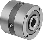
Sprag Engagement—Without Hub
 |
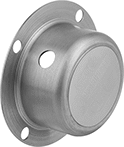 |
Clutch Covers |
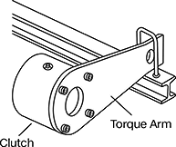 |
Torque Arm Shown Installed |
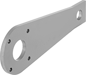 |
Clutch Torque Arms |
Sprag clutches handle higher torque than roller clutches because they have more contact points. This makes them best for backstopping applications.
Clutches without a hub have a precision ground outer race, so they can be press fit directly into a component and positioned anywhere along the length of your shaft. They also have mounting holes on their face you can use to secure your component or an anti-rotation device, such as a torque arm, for a different backstopping setup.
Through Shaft—Through-shaft clutches regulate torque transmission between an input shaft and a mounted component.
Slip-Fit Shaft Mount—Clutches that mount to shafts with a slip fit must be secured with a shaft collar or in some other way that prevents them from moving along the length of your shaft.
Clutch Covers—Covers protect you from rotating equipment when the clutch is mounted to the end of the shaft.
Clutch Torque Arms—Clutch torque arms work as an anchor for clutches in backstopping applications. Mount to the outer race of your clutch and a stationary piece of equipment.
Clutches | Clutch Covers | Clutch Torque Arms | |||||||||||||||||||||||||||||||||||||||||||||||||||||||||||||||||||||||||||||||||||||||||||||||||
|---|---|---|---|---|---|---|---|---|---|---|---|---|---|---|---|---|---|---|---|---|---|---|---|---|---|---|---|---|---|---|---|---|---|---|---|---|---|---|---|---|---|---|---|---|---|---|---|---|---|---|---|---|---|---|---|---|---|---|---|---|---|---|---|---|---|---|---|---|---|---|---|---|---|---|---|---|---|---|---|---|---|---|---|---|---|---|---|---|---|---|---|---|---|---|---|---|---|---|---|
Max. Rotation Speed, rpm | Shaft | Clockwise or Counterclockwise Drive | |||||||||||||||||||||||||||||||||||||||||||||||||||||||||||||||||||||||||||||||||||||||||||||||||
For Shaft Dia. | For Shaft Type | Max. Torque, ft·lbf | Inner-Race | Outer-Race | OD | Overall Lg. | Material | Keyway Wd. × Keyway Dp. | Mount Type | Each | Each | Each | |||||||||||||||||||||||||||||||||||||||||||||||||||||||||||||||||||||||||||||||||||||||
Through Shaft | |||||||||||||||||||||||||||||||||||||||||||||||||||||||||||||||||||||||||||||||||||||||||||||||||||
| 3/4" | Keyed | 300 | 2,800 | 850 | 3 1/2" | 2 3/4" | Steel | 3/16" × 3/32" | Slip Fit | 0000000 | 000000000 | 00000000 | 0000000 | 00000000 | 0000000 | ||||||||||||||||||||||||||||||||||||||||||||||||||||||||||||||||||||||||||||||||||||
| 1" | Keyed | 1,175 | 2,500 | 800 | 4 1/4" | 3 1/2" | Steel | 1/4" × 1/8" | Slip Fit | 0000000 | 00000000 | 00000000 | 000000 | 00000000 | 000000 | ||||||||||||||||||||||||||||||||||||||||||||||||||||||||||||||||||||||||||||||||||||
| 1 1/4" | Keyed | 1,175 | 2,500 | 800 | 4 1/4" | 3 1/2" | Steel | 1/4" × 1/8" | Slip Fit | 0000000 | 00000000 | 00000000 | 000000 | 00000000 | 000000 | ||||||||||||||||||||||||||||||||||||||||||||||||||||||||||||||||||||||||||||||||||||
| 1 1/2" | Keyed | 2,250 | 2,200 | 750 | 5 3/8" | 3 3/4" | Steel | 3/8" × 3/16" | Slip Fit | 0000000 | 00000000 | 00000000 | 000000 | 00000000 | 000000 | ||||||||||||||||||||||||||||||||||||||||||||||||||||||||||||||||||||||||||||||||||||
| 1 3/4" | Keyed | 2,250 | 2,200 | 750 | 5 3/8" | 3 3/4" | Steel | 3/8" × 3/16" | Slip Fit | 0000000 | 00000000 | 00000000 | 000000 | 00000000 | 000000 | ||||||||||||||||||||||||||||||||||||||||||||||||||||||||||||||||||||||||||||||||||||
Electric Clutches for Face-Mount Motors
Designed to mount directly to a NEMA face-mount motor, these clutches let you electrically control when to transmit power without turning off your motor. When you remove power to these clutches, they stop power transmission by disconnecting your motor's load. To the other side, attach a gearbox or couple a gear, sprocket, pulley, or other component.
Friction Engagement
 |
Through Shaft—Through-shaft clutches regulate torque transmission between an input shaft and a mounted component.
Set-Screw Shaft Mount—Clutches that mount to shafts with set screws bite into your shaft when tightened to hold it.
Clutch Controllers—Clutch controllers (sold separately) convert an AC input into a DC output to engage and disengage these clutches. They mount inside an electrical enclosure (sold separately).
Electrical Enclosures—Electrical enclosures (sold separately) attach directly to these clutches to protect wiring from dust and moisture.
Clutch Covers—Clutch covers (sold separately) change the open design of these clutches into a totally enclosed fan-cooled unit, protecting them from dust and moisture.
Clockwise-and-Counterclockwise Drive | |||||||||||||||||||||||||||||||||||||||||||||||||||||||||||||||||||||||||||||||||||||||||||||||||||
|---|---|---|---|---|---|---|---|---|---|---|---|---|---|---|---|---|---|---|---|---|---|---|---|---|---|---|---|---|---|---|---|---|---|---|---|---|---|---|---|---|---|---|---|---|---|---|---|---|---|---|---|---|---|---|---|---|---|---|---|---|---|---|---|---|---|---|---|---|---|---|---|---|---|---|---|---|---|---|---|---|---|---|---|---|---|---|---|---|---|---|---|---|---|---|---|---|---|---|---|
Max. Torque, ft·lbf | Max. Power, hp | Max. Rotation Speed, rpm | For Motor Frame Size | OD | Overall Lg. | Electric Clutch Type | Electrical Connection Permanence | Shaft Dia. | Keyway Wd. × Keyway Dp. | Material | Shaft Mount Type | Wire Lead Lg. | Voltage, V DC | Certification | Current, amp | Each | |||||||||||||||||||||||||||||||||||||||||||||||||||||||||||||||||||||||||||||||||||
Through Shaft | |||||||||||||||||||||||||||||||||||||||||||||||||||||||||||||||||||||||||||||||||||||||||||||||||||
| 16 | 3/4 | 3,600 | NEMA 48Y, NEMA 56C | 6 3/4" | 6 3/4" | Power On | Hardwire | 5/8" | 3/16" × 3/16" | Steel | Set Screw | 36" | 90 | UL Listed, C-UL Listed | 0.20 | 00000000 | 000000000 | ||||||||||||||||||||||||||||||||||||||||||||||||||||||||||||||||||||||||||||||||||
| 30 | 3 | 3,600 | NEMA 48Y, NEMA 56C | 6 3/4" | 6 3/4" | Power On | Hardwire | 5/8" | 3/16" × 3/16" | Steel | Set Screw | 36" | 90 | UL Listed, C-UL Listed | 0.23 | 00000000 | 00000000 | ||||||||||||||||||||||||||||||||||||||||||||||||||||||||||||||||||||||||||||||||||
Noncontact Magnetic Electric Brakes
 |
Create drag to slow or stop the motion of your drive system using magnetic force. Because torque is transmitted by magnetic force without contact, there is no wear, so these brakes give you accurate, repeatable braking. Also known as electric hysteresis brakes, they are often used in tensioning, holding, and stopping applications. The brake engages when the power is on and releases when it is off. The amount of electrical current determines the amount of torque that is applied by the brake. Use these brakes with a current-limiting transformer.
Keyway | Mounting Hole | ||||||||||||||||||||||||||||||||||||||||||||||||||||||||||||||||||||||||||||||||||||||||||||||||||
|---|---|---|---|---|---|---|---|---|---|---|---|---|---|---|---|---|---|---|---|---|---|---|---|---|---|---|---|---|---|---|---|---|---|---|---|---|---|---|---|---|---|---|---|---|---|---|---|---|---|---|---|---|---|---|---|---|---|---|---|---|---|---|---|---|---|---|---|---|---|---|---|---|---|---|---|---|---|---|---|---|---|---|---|---|---|---|---|---|---|---|---|---|---|---|---|---|---|---|---|
Shaft Dia. | Max. Torque, in·lbf | Max. Rotation Speed, rpm | OD | Overall Lg. | Shaft Type | Wd. | Dp. | Electric Brake Type | Drive Direction | Electrical Connection Permanence | Wire Lead Lg. | Voltage, V DC | Thread Size | Thread Pitch, mm | Each | ||||||||||||||||||||||||||||||||||||||||||||||||||||||||||||||||||||||||||||||||||||
Through Shaft | |||||||||||||||||||||||||||||||||||||||||||||||||||||||||||||||||||||||||||||||||||||||||||||||||||
| 0.118" | 0.2 | 1,990 | 1 1/4" | 1 5/8" | Round | — | — | Power On | Clockwise and Counterclockwise | Hardwire | 18" | 24 | M2.5 | 0.45 | 0000000 | 0000000 | |||||||||||||||||||||||||||||||||||||||||||||||||||||||||||||||||||||||||||||||||||
| 0.197" | 0.8 | 1,200 | 1 13/16" | 2" | D-Profile | — | — | Power On | Clockwise and Counterclockwise | Hardwire | 18" | 24 | M2.5 | 0.45 | 0000000 | 000000 | |||||||||||||||||||||||||||||||||||||||||||||||||||||||||||||||||||||||||||||||||||
| 0.197" | 1.3 | 760 | 2" | 2 1/8" | D-Profile | — | — | Power On | Clockwise and Counterclockwise | Hardwire | 18" | 24 | M3 | 0.5 | 0000000 | 000000 | |||||||||||||||||||||||||||||||||||||||||||||||||||||||||||||||||||||||||||||||||||
| 0.276" | 3.5 | 570 | 2 3/8" | 3" | D-Profile | — | — | Power On | Clockwise and Counterclockwise | Hardwire | 18" | 24 | M4 | 0.7 | 0000000 | 000000 | |||||||||||||||||||||||||||||||||||||||||||||||||||||||||||||||||||||||||||||||||||
| 0.394" | 11 | 590 | 3 5/8" | 4" | D-Profile | — | — | Power On | Clockwise and Counterclockwise | Hardwire | 18" | 24 | M4 | 0.7 | 0000000 | 000000 | |||||||||||||||||||||||||||||||||||||||||||||||||||||||||||||||||||||||||||||||||||
| 0.472" | 19 | 500 | 4 7/16" | 4 7/8" | Keyed | 0.158" | 0.098" | Power On | Clockwise and Counterclockwise | Hardwire | 18" | 24 | M5 | 0.8 | 0000000 | 000000 | |||||||||||||||||||||||||||||||||||||||||||||||||||||||||||||||||||||||||||||||||||
| 0.59" | 32 | 420 | 5 7/16" | 5 1/8" | Keyed | 0.197" | 0.124" | Power On | Clockwise and Counterclockwise | Hardwire | 18" | 24 | M5 | 0.8 | 0000000 | 00000000 | |||||||||||||||||||||||||||||||||||||||||||||||||||||||||||||||||||||||||||||||||||
