


About NEMA Straight-Blade Plugs, Connectors, and Receptacles
More
About NEMA Plugs, Sockets, and Receptacles
More
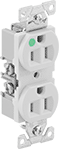
Sure-Grip Straight-Blade Plugs, Sockets, and Receptacles
Also known as hospital-grade connectors, these have an extra-tight fit when mated to remain secure in high-vibration environments. The housing is impact-resistant plastic.
Duplex receptacles fit standard wall plates (not included).
Quad receptacles have four outlets that are internally connected and can be wired as a single circuit or split into two circuits.
Note: The current rating of your plug should not exceed that of your socket or receptacle.
![]() For technical drawings and 3-D models, click on a part number.
For technical drawings and 3-D models, click on a part number.

| NEMA Style | Voltage | Current | Wire Connection Type | For Wire Gauge | Receptacle Terminal Location | Mounting Location | Features | Specifications Met | Choose a Color | Each | |
Grounded | |||||||||||
|---|---|---|---|---|---|---|---|---|---|---|---|
| 5-15 | 125V AC | 15A | Screw Terminals | 14-10 | Back, Side | Outlet Box | Green Dot | UL Listed, CSA Certified, Fed. Spec. W-C-596, UL 498 | 0000000 | 000000 | |
| 5-20 | 125V AC | 20A | Screw Terminals | 14-10 | Back, Side | Outlet Box | Green Dot | UL Listed, CSA Certified, Fed. Spec. W-C-596, UL 498 | 0000000 | 00000 | |
| 6-15 | 250V AC | 15A | Screw Terminals | 14-10 | Back, Side | Outlet Box | Green Dot | UL Listed, CSA Certified, Fed. Spec. W-C-596, UL 498 | Ivory | 0000000 | 00000 |
| 6-20 | 250V AC | 20A | Screw Terminals | 14-10 | Back, Side | Outlet Box | Green Dot | UL Listed, CSA Certified, Fed. Spec. W-C-596, UL 498 | 0000000 | 00000 | |

| NEMA Style | Voltage | Current | Wire Connection Type | For Wire Gauge | Receptacle Terminal Location | Mounting Location | Features | Specifications Met | Choose a Color | Each | |
Grounded | |||||||||||
|---|---|---|---|---|---|---|---|---|---|---|---|
| 5-15 | 125V AC | 15A | Screw Terminals | 14-12 | Side | Outlet Box | Green Dot | UL Listed, CSA Certified, UL 498 | 0000000 | 000000 | |
| 5-20 | 125V AC | 20A | Screw Terminals | 14-12 | Side | Outlet Box | Green Dot | UL Listed, CSA Certified, UL 498 | 0000000 | 00000 | |
Panel-Mount Straight-Blade Receptacles
Snap these receptacles into a cutout on an electrical panel—no screws or clips needed. They have snap-on terminals that pierce wire insulation, eliminating the need for wire stripping during wire installation.
![]() For technical drawings and 3-D models, click on a part number.
For technical drawings and 3-D models, click on a part number.

For Wire | For Panel | ||||||||||||
|---|---|---|---|---|---|---|---|---|---|---|---|---|---|
| NEMA Style | Voltage | Current | Wire Connection Type | Type | Gauge | Receptacle Terminal Location | Cutout Ht. | Cutout Wd. | Thick. | Features | Color | Each | |
Grounded | |||||||||||||
| 5-15 | 125V AC | 15A | Snap On | Solid | 14-12 | Back | 1" | 1" | 0.03"-0.07" | Mounting Tabs | Black | 000000 | 00000 |
Surge-Suppressing DIN-Rail Mount Straight-Blade Receptacles

Prevent damage to electronic equipment caused by spikes in voltage. Receptacles have an audible alarm to indicate a loss of surge protection. They mount to DIN rail to bring power closer to where you need it.
![]() For technical drawings and 3-D models, click on a part number.
For technical drawings and 3-D models, click on a part number.
| NEMA Style | Voltage | Current | Ht. | Wd. | Dp. | Wire Connection Type | For Wire Gauge | Receptacle Terminal Location | For DIN Rail Ht., mm | Features | Mounting Box Color | Color | Each | |
Grounded | ||||||||||||||
|---|---|---|---|---|---|---|---|---|---|---|---|---|---|---|
| 5-15 | 125V AC | 15A | 4.9" | 3.3" | 2.5" | Screw Terminals | 16-12 | Side | 35 | Audible Alarm, Power-Indicating Light | Gray | Gray | 0000000 | 0000000 |
DIN-Rail Mount Straight-Blade Receptacles
Bring power closer to where you need it by mounting receptacles to DIN rail.
![]() For technical drawings and 3-D models, click on a part number.
For technical drawings and 3-D models, click on a part number.

| NEMA Style | Voltage | Current | Ht. | Wd. | Dp. | Wire Connection Type | For Wire Gauge | Receptacle Terminal Location | For DIN Rail Ht., mm | Specifications Met | Color | Each | |
Grounded | |||||||||||||
|---|---|---|---|---|---|---|---|---|---|---|---|---|---|
| 5-15 | 125V AC | 15A | 2.8" | 1.4" | 2.3" | Screw Terminals | 26-12 | Front | 32, 35 | UL Recognized Component | Black | 0000000 | 000000 |

| NEMA Style | Voltage | Current | Ht. | Wd. | Dp. | Wire Connection Type | For Wire Gauge | Receptacle Terminal Location | For DIN Rail Ht., mm | Specifications Met | Color | Each | |
Grounded | |||||||||||||
|---|---|---|---|---|---|---|---|---|---|---|---|---|---|
| 5-15 | 125V AC | 15A | 3.9" | 1.7" | 2" | Screw Terminals | 14-12 | Front | 35 | CSA Certified, UL Recognized Component, C-UL Recognized Component, UL 498 | Black | 0000000 | 000000 |
GFCI DIN-Rail Mount Straight-Blade Receptacles

Keep personnel safe from electric shock by adding ground fault protection. Receptacles mount to DIN rail so you can bring power closer to where you need it. The housing is impact-resistant plastic.
![]() For technical drawings and 3-D models, click on a part number.
For technical drawings and 3-D models, click on a part number.
| NEMA Style | Voltage | Current | Ht. | Wd. | Dp. | Wire Connection Type | For Wire Gauge | Receptacle Terminal Location | For DIN Rail Ht., mm | Features | Mounting Box Color | Color | Each | |
Grounded | ||||||||||||||
|---|---|---|---|---|---|---|---|---|---|---|---|---|---|---|
| 5-15 | 125V AC | 15A | 5.625" | 3.3" | 2.5" | Screw Terminals | 16-12 | Side | 35 | Test Button | Gray | Gray | 0000000 | 0000000 |
| 5-20 | 125V AC | 20A | 5.625" | 3.3" | 2.5" | Screw Terminals | 16-12 | Side | 35 | Test Button | Gray | Gray | 0000000 | 000000 |
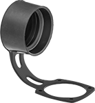
Safe-Break Pin-and-Sleeve Connectors
Connect and disconnect with the power on—spring-loaded contacts open like a switch when separating the connectors, preventing an electrical arc. These connectors are approved as switch-rated connectors for branch circuit and motor circuit disconnect switching. When mated, they form a NEMA 4X rated connection that resists corrosion and protects against washdowns. A ground pin is included in the number of wires.
Receptacles include a junction box with a conduit entry hub.
Finger drawplates (sold separately) create a grip around plugs and sockets or receptacles, making it easier to pull them together tightly when mating.
Caps (sold separately) protect plugs when not in use.
![]() For technical drawings and 3-D models, click on a part number.
For technical drawings and 3-D models, click on a part number.

| Face Dia. | No. of Poles | No. of Ground Connections | No. of Wires | Industry Designation | Electrical Phase | Current | Wire Connection Type | For Wire Gauge | For Cable OD | Temp. Range, °F | Environmental Rating | Choose a Voltage | Each | |
| 1.3" | 3 | 1 | 2 | 2W3P | Single | 20A | Screw Terminals | 14-12 | 0.35"-0.7" | -15° to 140° | IP66, IP67, IP69K, NEMA 4X | 125V AC | 00000000 | 000000 |
| 1.3" | 4 | 1 | 3 | 3W4P | Three | 20A | Screw Terminals | 14-12 | 0.35"-0.7" | -40° to 140° | IP66, IP67, IP69K, NEMA 4X | 0000000 | 00000 | |
| 1.8" | 3 | 1 | 2 | 2W3P | Single | 30A | Screw Terminals | 14-8 | 0.2"-0.82" | -15° to 140° | IP66, IP67, IP69K, NEMA 4X | 125V AC | 00000000 | 000000 |
| 1.9" | 4 | 1 | 3 | 3W4P | Three | 30A | Screw Terminals | 14-8 | 0.2"-0.82" | -40° to 140° | IP66, IP67, IP69K, NEMA 4X | 0000000 | 000000 |
 | 2W3P |
3W4P |
| Face Dia. | No. of Poles | No. of Ground Connections | No. of Wires | Industry Designation | Electrical Phase | Current | Wire Connection Type | For Wire Gauge | For Cable OD | Temp. Range, °F | Features | Environmental Rating | Choose a Voltage | Each | |
| 1.3" | 3 | 1 | 2 | 2W3P | Single | 20A | Screw Terminals | 14-12 | 0.35"-0.7" | -15° to 140° | Internal Shutters | IP66, IP67, IP69K, NEMA 4X | 125V AC | 00000000 | 0000000 |
| 1.3" | 4 | 1 | 3 | 3W4P | Three | 20A | Screw Terminals | 14-12 | 0.35"-0.7" | -40° to 140° | __ | IP66, IP67, IP69K, NEMA 4X | 0000000 | 000000 | |
| 1.8" | 3 | 1 | 2 | 2W3P | Single | 30A | Screw Terminals | 14-8 | 0.2"-0.82" | -15° to 140° | Internal Shutters | IP66, IP67, IP69K, NEMA 4X | 125V AC | 00000000 | 000000 |
| 1.8" | 4 | 1 | 3 | 3W4P | Three | 30A | Screw Terminals | 14-8 | 0.2"-0.82" | -40° to 140° | __ | IP66, IP67, IP69K, NEMA 4X | 0000000 | 000000 |
 | 2W3P |
3W4P |
Conduit | |||||||||||||||||
|---|---|---|---|---|---|---|---|---|---|---|---|---|---|---|---|---|---|
| Face Dia. | No. of Poles | No. of Ground Connections | No. of Wires | Industry Designation | Electrical Phase | Current | Wire Connection Type | For Wire Gauge | For Cable OD | Trade Size | Thread Type | Features | Temp. Range, °F | Environmental Rating | Choose a Voltage | Each | |
| 1.3" | 3 | 1 | 2 | 2W3P | Single | 20A | Screw Terminals | 14-12 | __ | 1 | NPT | Internal Shutters | -15° to 140° | IP66, IP67, IP69K, NEMA 4X | 125V AC | 00000000 | 0000000 |
| 1.7" | 4 | 1 | 3 | 3W4P | Three | 20A | Screw Terminals | 14-12 | __ | 1 | NPT | __ | -40° to 140° | IP66, IP67, IP69K, NEMA 4X | 0000000 | 000000 | |
| 1.8" | 3 | 1 | 2 | 2W3P | Single | 30A | Screw Terminals | 14-8 | __ | 1 | NPT | Internal Shutters | -15° to 140° | IP66, IP67, IP69K, NEMA 4X | 125V AC | 00000000 | 000000 |
| 1.9" | 4 | 1 | 3 | 3W4P | Three | 30A | Screw Terminals | 14-8 | 0.2"-0.82" | 1 | NPT | __ | -40° to 140° | IP66, IP67, IP69K, NEMA 4X | 0000000 | 000000 | |


Hazardous Location Safe-Break Pin-and-Sleeve Connectors
Use connectors where ignitable gas and dust may be present, such as in refineries and silos. They are CSA certified for Class I, Division 2, Groups A, B, C, and D; and Class II, Division 2, Groups F and G. All have a chamber that withstands the pressure of an internal ignition—isolating it from spreading to the surrounding environment. They're rated IP66 and IP67 for protection from washdowns and temporary submersion.
Finger drawplates (sold separately) create a grip around plugs and sockets or receptacles, making it easier to pull them together tightly when mating.
Caps (sold separately) protect plugs when not in use.
![]() For technical drawings and 3-D models, click on a part number.
For technical drawings and 3-D models, click on a part number.

| Face Dia. | No. of Poles | No. of Ground Connections | No. of Wires | Industry Designation | Electrical Phase | Current | Wire Connection Type | For Wire Gauge | For Cable OD | Temp. Range, °F | Choose a Voltage | Each | |
| 1.4" | 3 | 1 | 2 | 2W3P | Single | 20A | Screw Terminals | 16-10 | 0.44"-0.81" | -40° to 140° | 125V AC | 0000000 | 0000000 |
| 1.4" | 4 | 1 | 3 | 3W4P | Three | 20A | Screw Terminals | 16-10 | 0.44"-0.81" | -40° to 140° | 0000000 | 000000 | |
| 1.9" | 3 | 1 | 2 | 2W3P | Single | 30A | Screw Terminals | 14-6 | 0.44"-0.81" | -40° to 140° | 125V AC | 0000000 | 000000 |
| 1.9" | 4 | 1 | 3 | 3W4P | Three | 30A | Screw Terminals | 14-6 | 0.44"-0.81" | -40° to 140° | 0000000 | 000000 |
 | 2W3P |
3W4P |
Conduit | ||||||||||||||
|---|---|---|---|---|---|---|---|---|---|---|---|---|---|---|
| Face Dia. | No. of Poles | No. of Ground Connections | No. of Wires | Industry Designation | Electrical Phase | Current | Wire Connection Type | For Wire Gauge | Trade Size | Thread Type | Temp. Range, °F | Choose a Voltage | Each | |
| 1.4" | 3 | 1 | 2 | 2W3P | Single | 20A | Screw Terminals | 16-10 | 3/4 | NPT | -40° to 140° | 125V AC | 0000000 | 0000000 |
| 1.4" | 4 | 1 | 3 | 3W4P | Three | 20A | Screw Terminals | 16-10 | 3/4 | NPT | -40° to 140° | 0000000 | 000000 | |
| 1.9" | 3 | 1 | 2 | 2W3P | Single | 30A | Screw Terminals | 14-6 | 3/4 | NPT | -40° to 140° | 125V AC | 0000000 | 000000 |
| 1.9" | 4 | 1 | 3 | 3W4P | Three | 30A | Screw Terminals | 14-6 | 3/4 | NPT | -40° to 140° | 0000000 | 000000 | |
IEC Pin-and-Sleeve Connectors
These connectors meet international standards IEC 60309-1 and 60309-2, so they’re compatible with other IEC 60309 devices. They have a nonconductive nylon housing so they’re safer to use than components made of metal. Plugs have a notch that must line up with a keyway in sockets and receptacles when mating. All have a ground pin that is included in the number of wires.
IP44 rated connectors protect against damp environments.
![]() For technical drawings and 3-D models, click on a part number.
For technical drawings and 3-D models, click on a part number.

2W3P
Male
3W4P
Male
3W4P
Male
| Face Dia. | No. of Poles | No. of Ground Connections | No. of Wires | Industry Designation | Electrical Phase | Current | Wire Connection Type | For Wire Gauge | For Cable OD | Temp. Range, °F | Choose a Voltage | Each | |
Rated IP44 | |||||||||||||
|---|---|---|---|---|---|---|---|---|---|---|---|---|---|
| 1.3" | 3 | 1 | 2 | 2W3P | Single | 20A | Screw Terminals | 14-12 | 0.32"-0.55" | 0° to 120° | 125V AC | 000000000 | 000000 |
| 2" | 4 | 1 | 3 | 3W4P | Three | 20A | Screw Terminals | 16-12 | 0.33"-0.55" | -10° to 120° | 00000000 | 00000 | |
| 2.3" | 4 | 1 | 3 | 3W4P | Three | 30A | Screw Terminals | 14-8 | 0.49"-0.76" | -10° to 120° | 00000000 | 00000 | |

2W3P
Female
3W4P
Female
3W4P
Female
3W4P
Female
| Face Dia. | No. of Poles | No. of Ground Connections | No. of Wires | Industry Designation | Electrical Phase | Current | Wire Connection Type | For Wire Gauge | For Cable OD | Temp. Range, °F | Choose a Voltage | Each | |
Rated IP44 | |||||||||||||
|---|---|---|---|---|---|---|---|---|---|---|---|---|---|
| 1.3" | 3 | 1 | 2 | 2W3P | Single | 20A | Screw Terminals | 16-12 | 0.32"-0.55" | 0° to 120° | 125V AC | 000000000 | 000000 |
| 1.5" | 4 | 1 | 3 | 3W4P | Three | 20A | Screw Terminals | 16-12 | 0.33"-0.55" | 0° to 120° | 600V AC | 000000000 | 00000 |
| 2" | 4 | 1 | 3 | 3W4P | Three | 20A | Screw Terminals | 16-12 | 0.33"-0.55" | -10° to 120° | 00000000 | 00000 | |
| 2.3" | 4 | 1 | 3 | 3W4P | Three | 30A | Screw Terminals | 14-8 | 0.49"-0.76" | -10° to 120° | 00000000 | 00000 | |
Multipurpose Build-Your-Own Latching Connectors

Combine power, USB, computer, and compressed air inserts to build a connector that sends signal, power, and data. A complete connector requires a hood, a base, two frames, and a male and female insert for each slot in the frame. The frames fit into the hood and base, and the inserts snap into the frame. Select components based on the number of slots needed. Once assembled, connectors are rated NEMA 4X, 12, and IP65 for protection against dirt, washdowns, and oil/coolant dripping.
Crimpers (sold separately) are required for wire installation for crimp-on connectors. They ratchet to ensure the correct pressure is applied to every crimp.
Extraction tools (sold separately) make it easier to remove pins or sleeves from 17- and 20-pole power inserts.
![]() For technical drawings and 3-D models, click on a part number.
For technical drawings and 3-D models, click on a part number.


| Number of Poles | Voltage | Current | For Wire Gauge | For Number of Frame Slots | Max. Temp., °F | Specifications Met | Each | |
Plug | ||||||||
|---|---|---|---|---|---|---|---|---|
Screw Terminals | ||||||||
| 2 | 600V AC/600V DC | 40A | 14-9 | 1 | 255° | UL 94 V-0, DNV-GL Type Approved | 0000000 | 000000 |
| 3 | 600V AC/600V DC | 40A | 14-9 | 1 | 255° | UL 94 V-0 | 0000000 | 00000 |
Socket | ||||||||
Screw Terminals | ||||||||
| 2 | 600V AC/600V DC | 40A | 14-9 | 1 | 255° | UL 94 V-0, DNV-GL Type Approved | 0000000 | 00000 |
| 3 | 600V AC/600V DC | 40A | 14-9 | 1 | 255° | UL 94 V-0 | 0000000 | 00000 |
| Extraction Tool for 20-Pole Inserts | 0000000 | Each | 000000 |
High-Current Latching Connectors

Able to carry more than twice the current of standard latching signal/power connectors, these can be used with thermosensors or brakes on large motors. Use them to protect connections while maintaining access. The base and hood latch together securely, yet can be quickly detached for equipment repair or replacement. They’re rated NEMA 4X, 12, and IP65 for protection against corrosion, washdowns, dirt, oil/coolant dripping, and water projected from a nozzle.
4-pole connector has two control pins to prevent arcing if it is disconnected before the power is turned off.
![]() For technical drawings and 3-D models, click on a part number.
For technical drawings and 3-D models, click on a part number.
Conduit | ||||||||||||||||
|---|---|---|---|---|---|---|---|---|---|---|---|---|---|---|---|---|
| Number of Poles | Number of Control Pins | Voltage | Control Pin Voltage | Current | Trade Size | Thread Type | Connection Gender | Wire Connection Type | For Wire Gauge | Lg. | Wd. | Ht. | Max. Temp., °F | Specifications Met | Each | |
Side Conduit Connection—2 Latching Levers | ||||||||||||||||
Powder-Coated Aluminum | ||||||||||||||||
| 4 | 2 | 600V AC/600V DC | 300V AC | 80A | 1 | NPT | Female | Screw Terminals | 16-6 | 4.5" | 1.7" | 4.1" | 255° | UL Recognized Component | 000000 | 0000000 |
High-Current Compact Latching Connectors

Carry up to four times the current of standard compact latching signal/power connectors. To protect connections while maintaining access, the base and hood latch together securely, yet can be quickly detached for equipment repair or replacement. They’re rated IP65 for protection against dirt and water projected from a nozzle.
![]() For technical drawings and 3-D models, click on a part number.
For technical drawings and 3-D models, click on a part number.
Conduit | |||||||||||||||
|---|---|---|---|---|---|---|---|---|---|---|---|---|---|---|---|
| Number of Poles | Voltage | Current | Trade Size | Thread Type | Connection Gender | Wire Connection Type | For Wire Gauge | Lg. | Wd. | Ht. | Max. Temp., °F | Environmental Rating | Specifications Met | Each | |
Side Conduit Connection—1 Latching Lever | |||||||||||||||
Nickel-Plated Zinc | |||||||||||||||
| 3 | 600V AC/600V DC | 40A | 3/4 | NPT | Female | Screw Terminals | 14-10 | 1.9" | 1.4" | 3.3" | 255° | IP65 | UL Recognized Component | 000000 | 0000000 |
Stackable Connectors
Stack as many connectors as you need—the housings clamp together for secure connections.
Connectors with screw terminals require a 2 mm hex key to install wire.
![]() For technical drawings and 3-D models, click on a part number.
For technical drawings and 3-D models, click on a part number.


Mated Housing | |||||||||||||
|---|---|---|---|---|---|---|---|---|---|---|---|---|---|
| Number of Poles | Voltage | Current | For Cable OD | For Wire Gauge | Color | Housing Material | Lg. | Wd. | Ht. | Max. Temp., °F | Specifications Met | Each | |
Plug | |||||||||||||
Screw Terminals | |||||||||||||
| 2 | 600V AC/600V DC | 40A | 0.39"-0.55" | 14-8 | Gray | Polycarbonate Plastic | 2.8" | 1.8" | 0.9" | 255° | UL Recognized Component | 0000000 | 000000 |
Socket | |||||||||||||
Screw Terminals | |||||||||||||
| 2 | 600V AC/600V DC | 40A | 0.39"-0.55" | 14-8 | Gray | Polycarbonate Plastic | 2.8" | 1.8" | 0.9" | 255° | UL Recognized Component | 0000000 | 00000 |
Stackable Pin-to-Pin Connectors

Stack housings and lock them together to form a connector with as many poles as you need. Connectors have a slotted dovetail on each side—align the slots and slide the housings together to lock. An internal stainless steel spring ensures that the pins maintain constant pressure. Current rating is based on a single-pole configuration using the largest wire shown within each range. Also known as power-pole connectors.
Enclosures (sold separately) hold four connectors.
![]() For technical drawings and 3-D models, click on a part number.
For technical drawings and 3-D models, click on a part number.

Connectors | |||||||||||||||
|---|---|---|---|---|---|---|---|---|---|---|---|---|---|---|---|
Mated Housing | Replacement Housings | ||||||||||||||
| Current | Voltage | No. of Poles | Wire Connection Type | For Wire Gauge | Lg. | Wd. | Ht. | Temp. Range, °F | Choose a Color | Pkg. Qty. | Pkg. | Pkg. Qty. | Pkg. | ||
| 30A | 600V AC/600V DC | 1 | Crimp On | 16-12 | 1.6" | 0.3" | 0.3" | 0° to 220° | 5 | 000000 | 00000 | 5 | 000000 | 00000 | |
| 45A | 600V AC/600V DC | 1 | Crimp On | 14-10 | 1.6" | 0.3" | 0.3" | 0° to 220° | 5 | 000000 | 0000 | 5 | 000000 | 0000 | |

| For No. of Connectors | Housing Material | Lg. | Wd. | Ht. | Temp. Range, °F | Color | Each | |
| 4 | Polycarbonate Plastic | 1.9" | 1.2" | 0.9" | 0° to 220° | Black | 0000000 | 00000 |

Weatherproof DC Connector Sets
Also known as weather-pack connectors, these can withstand moisture, harsh engine fluids, and high temperatures. They have wire seals to provide an environmental seal between the wire and pin or sleeve. Use them in construction, off-road, and agricultural equipment. Each set includes a plug and a socket.
An extraction tool (sold separately) is required to release the locking mechanism on pins and sleeves so that they can be removed from the housing.
A crimper (sold separately) is required for wire installation.
![]() For technical drawings and 3-D models, click on a part number.
For technical drawings and 3-D models, click on a part number.


Sets | |||||||||||||
|---|---|---|---|---|---|---|---|---|---|---|---|---|---|
Mated Housing | Extraction Tools | Non-Ratcheting Crimper | |||||||||||
| Voltage | Current | For Wire Gauge | Lg. | Wd. | Ht. | Color | Temp. Range, °F | Each | Each | Each | |||
1-Pole | |||||||||||||
| 16V DC | 30A | 14-12 | 2.7" | 0.7" | 0.9" | Black | -40° to 255° | 0000000 | 000000 | 000000 | 00000 | 000000 | 000000 |
2-Pole | |||||||||||||
| 16V DC | 30A | 14-12 | 2.7" | 1" | 1" | Black | -40° to 255° | 0000000 | 00000 | 000000 | 0000 | 000000 | 00000 |
3-Pole | |||||||||||||
| 16V DC | 30A | 14-12 | 2.9" | 1.3" | 1" | Black | -40° to 255° | 0000000 | 00000 | 000000 | 0000 | 000000 | 00000 |
Deutsch-Style DC Connectors
Use these connectors in vehicles and other agricultural and construction equipment.
Connectors with a crimp-on connection require a crimper (sold separately) for wire installation.
When mated, IP67 rated connectors create a dust- and watertight seal, even if briefly submersed.
![]() For technical drawings and 3-D models, click on a part number.
For technical drawings and 3-D models, click on a part number.


| For Wire Gauge (Connector Insulation) | For Wire Type | For Pin-and-Sleeve Barrel Type | Ratcheting or Nonratcheting | Lg. | Material | Each | |
For Pin-and-Sleeve, D-Sub, and DT Deutsch-Style Connectors | |||||||
|---|---|---|---|---|---|---|---|
| 20-12 (Noninsulated) | Stranded | Open, Closed | Nonratcheting | 11" | Steel | 000000 | 000000 |
| For Connector Current | For Wire Gauge | Pkg. Qty. | Pkg. | |
| 25A | 14-12 | 10 | 0000000 | 000000 |
| For Connector Current | For Wire Gauge | Pkg. Qty. | Pkg. | |
| 25A | 14-12 | 10 | 0000000 | 000000 |
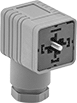
Solenoid Valve Connectors
Connect hydraulic and air-powered valves, motors, pumps, and pressure switches.
IP65 rated connectors protect against water projected from a nozzle.
![]() For technical drawings and 3-D models, click on a part number.
For technical drawings and 3-D models, click on a part number.
Thread | ||||||||||||||||
|---|---|---|---|---|---|---|---|---|---|---|---|---|---|---|---|---|
| Number of Poles | Current | For Wire Gauge | For Cable OD | Cable Orientation | Color | Size | Pitch, mm | Thread Type | Lg. | Wd. | Ht. | Features | Max. Temp., °F | Environmental Rating | Each | |
Type BI—0.43" (11 mm) Contact Distance | ||||||||||||||||
24V AC/24V DC | ||||||||||||||||
| 3 | 4A | 16, 15, 14, 13, 12 | 0.2"-0.39" | Opposite Ground Terminal | Gray | M16 | 1.5 | Metric | 0.87" | 1.61" | 1.77" | Power-Indicating Light | 140° | IP65 | 00000000 | 000000 |
| 3 | 4A | 16, 15, 14, 13, 12 | 0.24"-0.32" | Opposite Ground Terminal | Gray | PG-9 | __ | PG | 0.87" | 1.61" | 1.77" | Power-Indicating Light | 140° | IP65 | 00000000 | 00000 |
Fluorescent Ballast Connectors


Avoid exposure to live wires when replacing ballasts. To install, push the wires between the ballast and the power source into the connector. Each set includes a male plug and a female socket. All comply with NEC requirements for connecting fluorescent lights.
Connectors for three wires are for fixtures with an integral switch or dimmer.
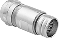
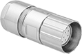
Servomotor M23 Connectors


with
Mounting Holes
Use these connectors with servomotor, servocontrollers, and servodrives in automated equipment and assembly lines. Rated NEMA 4X, IP67, and IP69K, they resist corrosion and protect against high-pressure, high-temperature washdowns. When mating connectors, the gender, housing thread location, and pole layout must be opposite. Poles are numbered on the face of the connector.
Power connectors deliver electricity to run a servomotor.
![]() For technical drawings and 3-D models, click on a part number.
For technical drawings and 3-D models, click on a part number.

Clockwise
(12 Pole Shown)


Counterclockwise
(12 Pole Shown)
High-Current | ||||||||||
|---|---|---|---|---|---|---|---|---|---|---|
| No. of Poles | Pole Layout | No. of Poles | Current | Voltage | For Wire Gauge | For Cable OD | OD | For Panel Cutout Dia. | Each | |
Plug—External Thread | ||||||||||
| 6 | Clockwise | 6 | 28A | 600V AC/600V DC | 14-12 | 0.27"-0.47" | 1" | __ | 0000000 | 000000 |
Socket—Internal Thread | ||||||||||
| 6 | Counterclockwise | 6 | 28A | 600V AC/600V DC | 14-12 | 0.27"-0.47" | 1.1" | __ | 0000000 | 00000 |
Receptacle—External Thread | ||||||||||
| 6 | Clockwise | 6 | 28A | 600V AC/600V DC | 14-12 | __ | __ | 1" | 0000000 | 00000 |
Receptacle with 4 Mounting Holes—External Thread | ||||||||||
| 6 | Clockwise | 6 | 28A | 600V AC/600V DC | 14-12 | __ | __ | 0.79" | 0000000 | 00000 |
Turn-Lock Vehicle DC Connectors
Lock connectors into place for a secure connection in high-vibration environments. The turn-lock design prevents attachment to AC connectors. They power ancillary devices, such as chargers for electronics, from a vehicle. All have corrosion-resistant electrical components.
Plugs have an O-ring that seals out moisture when connected to a socket.
![]() For technical drawings and 3-D models, click on a part number.
For technical drawings and 3-D models, click on a part number.
