


About Vacuum Pumps
More
About Air Compressors
More
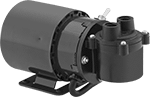
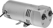
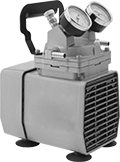
Oil-Free Electric Vacuum Pumps
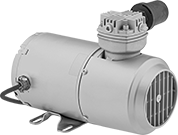
Since these pumps don't require lubrication, there’s no risk of oil contamination. Maximum flow rate is the rate at which air is pumped before a vacuum is created. Flow rate steadily decreases as the pump generates the vacuum. The larger the tank, the longer it will take to form a vacuum.
Style A pumps are often used for air and gas sampling, controlling compressed air flow, and vacuum filtration. They are also suitable for pressure applications up to 18 psi.
Style B pumps are often used for aeration, leak detection, and liquid-level control.
Style C pumps withstand harsh operating conditions. Use to service machinery and refrigeration and circulation systems.
Intake | Discharge | O'all | |||||||||||||||
|---|---|---|---|---|---|---|---|---|---|---|---|---|---|---|---|---|---|
| Style | Max. Vacuum, in. of Hg | Max. Flow Rate, cfm | Temp. Range, °F | Volume, dBA | Horsepower | Current, A | Pipe Size | Thread Type | Gender | Pipe Size | Thread Type | Gender | Lg. | Wd. | Ht. | Each | |
NEMA 5-15 Plug | |||||||||||||||||
| C | 27.5 | 1.75 | 35° to 100° | 70 | 1/6 hp | 3.5 | 1/4 | NPT | Female | 1/4 | NPT | Female | 11 1/2" | 5 5/8" | 8 5/8" | 000000 | 0000000 |
Intake | Discharge | O'all | |||||||||||||||
|---|---|---|---|---|---|---|---|---|---|---|---|---|---|---|---|---|---|
| Style | Max. Vacuum, in. of Hg | Max. Flow Rate, cfm | Temp. Range, °F | Volume, dBA | Horsepower | Current, A | Pipe Size | Thread Type | Gender | Pipe Size | Thread Type | Gender | Lg. | Wd. | Ht. | Each | |
NEMA 5-15 Plug | |||||||||||||||||
| C | 27.5 | 5 | 35° to 100° | 75 | 1/2 hp | 6/12 | 1/4 | NPT | Female | 1/4 | NPT | Female | 13 1/4" | 12 3/8" | 9" | 000000 | 000000000 |
Hardwire | |||||||||||||||||
| C | 27.5 | 10.5 | 35° to 100° | 75 | 1 1/2 hp | 10/21 | 1/4 | NPT | Female | 1/4 | NPT | Female | 21" | 12 1/4" | 8 1/2" | 000000 | 00000000 |
Intake | Discharge | O'all | ||||||||||||||
|---|---|---|---|---|---|---|---|---|---|---|---|---|---|---|---|---|
| Style | Max. Vacuum, in. of Hg | Max. Flow Rate, cfm | Max. Pressure, psi | Temp. Range, °F | Volume, dB | Horsepower | Current, A | Connection Style | For Tube ID | Connection Style | For Tube ID | Lg. | Wd. | Ht. | Each | |
NEMA 5-15 Plug | ||||||||||||||||
| A | 20 | 0.6 | 18 | 35° to 100° | 72 | 1/45 hp | 1.2 | Barbed | 3/8" | Barbed | 3/8" | 7 1/4" | 4" | 5 1/2" | 00000000 | 0000000 |
Intake | Discharge | O'all | ||||||||||||||||
|---|---|---|---|---|---|---|---|---|---|---|---|---|---|---|---|---|---|---|
| Style | Max. Vacuum, in. of Hg | Max. Flow Rate, cfm | Max. Pressure, psi | Temp. Range, °F | Volume, dBA | Horsepower | Current, A | Pipe Size | Thread Type | Gender | Pipe Size | Thread Type | Gender | Lg. | Wd. | Ht. | Each | |
NEMA 5-15 Plug | ||||||||||||||||||
| B | 26 | 4.5 | 10 | 30° to 100° | 70 | 1/4 hp | 2.1/4.3 | 1/4 | NPT | Female | 1/4 | NPT | Female | 14" | 5 5/8" | 6" | 0000000 | 0000000 |
Oil-Free Electric Vacuum Pumps with Tank
Generate a vacuum on demand with these pumps that come mounted on a 10-gal. ASME code vacuum tank for quick startup. They're often used in vacuum-forming applications, such as product packaging. They need no lubrication, so oil won't contaminate your process. Maximum flow rate is the rate at which air is pumped before a vacuum is created. Flow rate steadily decreases as the pump generates the vacuum. The larger the tank, the longer it will take to form a vacuum. Tube and fitting ID will also affect flow.
Intake | Discharge | Overall | ||||||||||||||
|---|---|---|---|---|---|---|---|---|---|---|---|---|---|---|---|---|
| Max. Vacuum, in. of Hg | Max. Flow Rate, cfm | Temp. Range, °F | Volume, dBA | Horsepower | Current, A | Tube Connection Type | For Tube ID | Pipe Size | Thread Type | Gender | Lg. | Wd. | Ht. | Includes | Each | |
120V AC, Single Phase—With Thermal Overload Protection | ||||||||||||||||
NEMA 5-15 Plug | ||||||||||||||||
| 26 | 7.1 | 45° to 100° | 58 | 1/3 hp | 4 | Barbed | 3/8" | 3/8 | NPT | Female | 30" | 12 3/8" | 24 1/2" | 10-gal. ASME-Code Vacuum Tank, Muffler, Shut-Off Valve, Three-Position Switch, Vacuum Gauge | 0000000 | 000000000 |
Portable Oil-Free Electric Vacuum Pumps
These pumps weigh only 16 pounds and have a handle, so they're convenient for on-site sampling, atomizing, and vacuum filtration. They're also for use in pressure applications up to 60 psi. Since they don't require lubrication, there’s no risk of oil contamination. Maximum flow rate is the rate at which air is pumped before a vacuum is created. Flow rate steadily decreases as the pump generates the vacuum. The larger the tank, the longer it will take to form a vacuum. Tube and fitting ID will also affect flow.
Repair kits include filter/muffler components, a gasket, a leaf valve, limiters, and an O-ring.
Pumps | |||||||||||||||||
|---|---|---|---|---|---|---|---|---|---|---|---|---|---|---|---|---|---|
Intake | Discharge | Overall | Repair Kits | ||||||||||||||
| Max. Vacuum, in. of Hg | Max. Flow Rate, cfm | Max. Pressure, psi | Temp. Range, °F | Volume, dBA | Horsepower | Current, A | Tube Connection Type | For Tube ID | Tube Connection Type | For Tube ID | Lg. | Wd. | Ht. | Each | Each | ||
120V AC, Single Phase—With Thermal Overload Protection | |||||||||||||||||
NEMA 5-15 Plug | |||||||||||||||||
| 25.5 | 1.1 | 60 | 35° to 100° | 65 | 1/8 hp | 4.2 | Barbed | 3/8" | Barbed | 3/8" | 7 3/4" | 5 7/8" | 11" | 0000000 | 0000000 | 0000000 | 000000 |
Electric Vacuum Pumps
 | NEMA 5-15 |
NEMA 6-15 |
Use these pumps in applications such as degassing and servicing refrigeration and freezer systems. Maximum flow rate is the rate at which air is pumped before a vacuum is created. Flow rate steadily decreases as the pump generates the vacuum. The larger the tank, the longer it will take to form a vacuum. Tube and fitting ID will also affect flow.
Intake | Discharge | Overall | |||||||||||||||
|---|---|---|---|---|---|---|---|---|---|---|---|---|---|---|---|---|---|
| Max. Vacuum | Max. Flow Rate, cfm | Temp. Range, °F | Volume, dBA | Horsepower | Current, A | Port Size | Tube Connection Type | Gender | Pipe Size | Thread Type | Gender | Lg. | Wd. | Ht. | Oil Capacity, oz. | Each | |
115V AC, Single Phase—With Thermal Overload Protection | |||||||||||||||||
NEMA 5-15 Plug | |||||||||||||||||
| 10 -2 torr @ 72° F | 3 | 30° to 180° | 70 | 1/2 hp | 7 | 1/4", 3/8", 1/2" | Flared | Male | 1/2 | NPT | Male | 14 1/2" | 5 5/8" | 12" | 27 | 0000000 | 0000000 |
| 10 -2 torr @ 72° F | 5 | 30° to 180° | 70 | 1/2 hp | 7 | 1/4", 3/8", 1/2" | Flared | Male | 1/2 | NPT | Male | 14 1/2" | 5 5/8" | 12" | 21 | 0000000 | 000000 |
| 10 -2 torr @ 72° F | 7 | 30° to 180° | 70 | 1/2 hp | 7 | 1/4", 3/8", 1/2" | Flared | Male | 1/2 | NPT | Male | 14 1/2" | 5 5/8" | 12" | 23 | 0000000 | 000000 |
| 10 -2 torr @ 72° F | 10 | 30° to 180° | 70 | 1/2 hp | 7 | 1/4", 3/8", 1/2" | Flared | Male | 1/2 | NPT | Male | 14 1/2" | 5 5/8" | 12" | 26 | 0000000 | 000000 |
115V AC/230V AC, Single Phase—With Thermal Overload Protection | |||||||||||||||||
NEMA 6-15 Plug | |||||||||||||||||
| 10 -2 torr @ 72° F | 3 | 30° to 180° | 70 | 1/2 hp | 3.5/7 | 1/4", 3/8", 1/2" | Flared | Male | 1/2 | NPT | Male | 14 1/2" | 5 5/8" | 12" | 27 | 0000000 | 000000 |
| 10 -2 torr @ 72° F | 5 | 30° to 180° | 70 | 1/2 hp | 3.5/7 | 1/4", 3/8", 1/2" | Flared | Male | 1/2 | NPT | Male | 14 1/2" | 5 5/8" | 12" | 21 | 0000000 | 000000 |
| 10 -2 torr @ 72° F | 7 | 30° to 180° | 70 | 1/2 hp | 3.5/7 | 1/4", 3/8", 1/2" | Flared | Male | 1/2 | NPT | Male | 14 1/2" | 5 5/8" | 12" | 21 | 0000000 | 000000 |
| 10 -2 torr @ 72° F | 10 | 30° to 180° | 70 | 1/2 hp | 3.5/7 | 1/4", 3/8", 1/2" | Flared | Male | 1/2 | NPT | Male | 16" | 5 5/8" | 12" | 26 | 0000000 | 000000 |
Electric High-Vacuum Pumps


Achieve powerful vacuum and continuous flow for applications such as vacuum drying, solvent evaporation, and distillation. Maximum flow rate is the rate at which air is pumped before a vacuum is created. Flow rate steadily decreases as the pump generates the vacuum. The larger the tank, the longer it will take to form a vacuum. Tube and fitting ID will also affect flow.
Intake | Overall | ||||||||||||||
|---|---|---|---|---|---|---|---|---|---|---|---|---|---|---|---|
| Max. Vacuum | Max. Flow Rate, cfm | Temp. Range, °F | Volume, dBA | Horsepower | Current, A | Connection Style | Gender | For Tube ID | Discharge Connection Style | Lg. | Wd. | Ht. | Oil Capacity, qt. | Each | |
115V AC, Single Phase—With Thermal Overload Protection | |||||||||||||||
NEMA 5-15 Plug | |||||||||||||||
| 10 -3 torr @ 72° F | 2.8 | 50° to 100° | 50 | 1/2 hp | 5.3 | Quick Clamp | Female | __ | Quick Clamp Hose | 18 1/4" | 6 1/8" | 9 1/8" | 1.22 | 0000000 | 000000000 |
| 10 -3 torr @ 72° F | 12.8 | 50° to 100° | 55 | 1 hp | 8 | Quick Clamp | Female | __ | Quick Clamp Hose | 22 3/8" | 8 1/8" | 11 3/8" | 2.55 | 0000000 | 00000000 |
120V AC, Single Phase—Without Thermal Overload Protection | |||||||||||||||
NEMA 5-15 Plug | |||||||||||||||
| 10 -4 torr @ 72° F | 0.9 | 50° to 100° | 54 | 1/3 hp | 5 | Barbed | Male | 7/16" | Open Outlet | 17 7/8" | 9" | 12 5/8" | 0.63 | 0000000 | 00000000 |
| 10 -4 torr @ 72° F | 3.2 | 50° to 100° | 54 | 1/2 hp | 7 | Barbed | Male | 7/16" | Open Outlet | 20" | 12" | 15" | 2.25 | 0000000 | 00000000 |
| 10 -4 torr @ 72° F | 5.6 | 50° to 100° | 54 | 1/2 hp | 7 | Barbed | Male | 13/16" | Open Outlet | 20" | 12" | 15" | 2.25 | 0000000 | 00000000 |
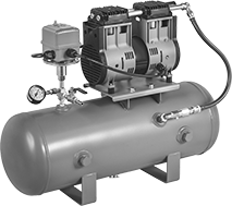
Electric Ultra-High-Vacuum Pumps
Achieve vacuum levels up to 1 x 10 -12 torr with these ultra-high-vacuum pumps. Each unit includes two pumps—a diaphragm pump and a turbomolecular pump—that work together to create extremely high levels of vacuum in your chamber. The turbomolecular pump meets IP54 for protection in damp and dusty environments. Units are compact, so they fit on top of a workbench or table.
Pumps are ready to use as soon as they’re plugged in and connected to a chamber. Since they don’t use oil, they won’t introduce contaminants into your system. They hardly vibrate, minimizing interference with sensitive instruments and measurement devices.
Pumps with claw-clamp intake connections require a ring and four double-claw clamps (all sold separately) to connect to other components. Claw-clamp connections are also known as ISO-K fittings. These pumps include a gauge with quick-clamp connections, which requires a quick clamp and a ring (both sold separately) to connect. Quick-clamp connections are also known as KF fittings.
Pumps with flanged intake connections and the included gauge each require a gasket (sold separately) to connect to your chamber. Flanged connections are also known as CF fittings.

Intake Connection | Gauge Port Connection | Discharge Connection (BSPP Threads) | O'all | ||||||||||||||
|---|---|---|---|---|---|---|---|---|---|---|---|---|---|---|---|---|---|
| Max. Vacuum | Max. Flow Rate, cfm | Volume, dBA | Current, A | For Tube OD | Flange OD | High-Vacuum Flange Size | High Vacuum Connection Type | For Tube OD | Flange OD | High-Vacuum Flange Size | High Vacuum Connection Type | Pipe Size | Gender | Ht. | Wd. | Each | |
Claw-Clamp Intake Connection—120V AC/240V AC, Single Phase | |||||||||||||||||
| 1 × 10 -8 torr @ 72° F | 142 | 50 | 4.6 | 2 1/2" | 3 3/4" | 63 | ISO-K | 1" | 1.57" | 25 | ISO-KF | 1/8 | Male | 13 5/8" | 11 7/8" | 000000 | 000000000 |
Flanged Intake Connection—120V AC/240V AC, Single Phase | |||||||||||||||||
| 1 × 10 -12 torr @ 72° F | 142 | 50 | 4.6 | 2 1/2" | 4 1/2" | 63 | CF | 1 1/2" | 2 3/4" | 40 | CF | 1/8 | Male | 13 7/8" | 11 7/8" | 000000 | 00000000 |


| For Tube OD | For Flange OD | For High-Vacuum Flange Size | High Vacuum Connection Type | Material | Max. Vacuum | Each | |
For Claw-Clamp Intake Connection—Double-Claw with Bolt | |||||||
|---|---|---|---|---|---|---|---|
| 2 1/2", 3", 4" | 3.74", 4.33", 5.12" | 63, 80, 100 | ISO-K | Aluminum | 1 × 10 -9 torr @ 72° F | 0000000 | 00000 |
For Quick-Clamp Gauge Connection—Clamp with Wing Nut | |||||||
| 1" | 1.57" | 25 | ISO-KF | Aluminum | 1 × 10 -7 torr @ 72° F | 0000000 | 00000 |

Material | |||||||||
|---|---|---|---|---|---|---|---|---|---|
| For Tube OD | For Flange OD | For High-Vacuum Flange Size | High Vacuum Connection Type | O-Ring | Inner Ring | Max. Vacuum | Max. Temp., °F | Each | |
For Claw-Clamp Intake Connection | |||||||||
| 2 1/2" | 3.74" | 63 | ISO-K | Viton® Fluoroelastomer Rubber | 304 Stainless Steel | 1 × 10 -9 torr @ 72° F | 400° | 0000000 | 000000 |
For Quick-Clamp Gauge Connection | |||||||||
| 1" | 1.57" | 25 | ISO-KF | Fluoroelastomer Rubber | 304 Stainless Steel | 1 × 10 -7 torr @ 72° F | 300° | 0000000 | 00000 |

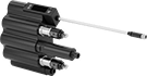
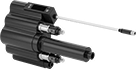
Robot-Arm-Mounted Electric Vacuum Pumps

Generate the suction you need to power end-of-arm tools, such as vacuum cups and grippers, without using an installed vacuum system. These pumps, also known as venturi devices, connect to any compressed air source and come with all the electrical connections you need to start lifting or moving objects. They’re curved and have a foam mounting pad that fits collaborative robot arms. Use the hook-and-loop straps to secure them in place—close to your tools, but out of the way.
These pumps have a vacuum switch that uses analog and PNP digital feedback to send information about the pump’s vacuum level to your controller. The switch has an LED display that shows the vacuum setting and status. Push buttons on the pump let you set and change the vacuum setting. An integrated solenoid valve controls the air flow to your tools.
Vacuum pumps with a discharge tube have an additional integrated solenoid valve that creates a burst of air for removing parts that may not drop when the air flow stops, such as those with adhesive on them.
Vacuum pumps with M8 plug will work with FANUC CRX and Universal Robots models. They include a USB flash drive with software for Universal Robots, called URCap, that plugs into your teach pendant to program the pump.
![]() For technical drawings and 3-D models, click on a part number.
For technical drawings and 3-D models, click on a part number.

Intake, Push to Connect | Vacuum Connection, Push to Connect | O'all | ||||||||||||
|---|---|---|---|---|---|---|---|---|---|---|---|---|---|---|
| Max. Vacuum | Max. Flow Rate, cfm | Operating Pressure, psi | Temp. Range, °F | Volume, dBA | Current, A | Tube OD, mm | Gender | Tube OD, mm | Gender | Lg. | Ht. | For Robot Arm Manufacturer (Series/Model No.) | Each | |
24V DC, Single Phase | ||||||||||||||
With Wire Leads | ||||||||||||||
| 27 in. of Hg @ 72° F | 5 | 120 | 0° to 120° | 70 | 0.17 | 6 | Female | 6 | Female | 4 3/8" | 5 5/8" | __ | 0000000 | 0000000 |
With M8 Plug | ||||||||||||||
| 27 in. of Hg @ 72° F | 5 | 120 | 0° to 120° | 70 | 0.17 | 6 | Female | 6 | Female | 4 3/8" | 5 5/8" | FANUC (CRX 5iA, 10iA, 10iA/L, 20iA/L, 25iA) Universal Robots (UR3; UR3e; UR5; UR5e; UR10; UR10e; UR16; UR16e) | 0000000 | 000000 |

Intake, Push to Connect | Discharge, Push to Connect | Vacuum Connection, Push to Connect | O'all | |||||||||||||
|---|---|---|---|---|---|---|---|---|---|---|---|---|---|---|---|---|
| Max. Vacuum | Max. Flow Rate, cfm | Operating Pressure, psi | Temp. Range, °F | Volume, dBA | Current, A | Tube OD, mm | Gender | Tube OD, mm | Gender | Tube OD, mm | Gender | Lg. | Ht. | For Robot Arm Manufacturer (Series/Model No.) | Each | |
24V DC, Single Phase | ||||||||||||||||
With Wire Leads | ||||||||||||||||
| 18 in. of Hg @ 72° F | 5 | 120 | 0° to 120° | 74 | 0.17 | 6 | Female | 6 | Female | 10 | Female | 4 3/8" | 7" | __ | 0000000 | 0000000 |
With M8 Plug | ||||||||||||||||
| 18 in. of Hg @ 72° F | 5 | 120 | 0° to 120° | 74 | 0.17 | 6 | Female | 6 | Female | 10 | Female | 4 3/8" | 7" | FANUC (CRX 5iA, 10iA, 10iA/L, 20iA/L, 25iA) Universal Robots (UR3; UR3e; UR5; UR5e; UR10; UR10e; UR16; UR16e) | 0000000 | 000000 |
High-Flow Low-Pressure Compressed Air Blowers
Also known as regenerative blowers, use these to produce high-flow compressed air with low pressure or vacuum to operate pump drives, lift tables, and conveying systems. Compressed air blowers are also used for drying, exhausting, and aeration.
Air circulates inside the blower housing to compress air, which generates pressure or vacuum. Single-stage blowers circulate air once and then exhaust. Two-stage blowers circulate air twice and then exhaust, creating higher pressure or vacuum than single-stage blowers with the same horsepower.
Inverter-rated blowers have a motor that can run at slow speeds without overheating, so they can be used with a motor speed control (variable frequency drive).
![]() For technical drawings and 3-D models, click on a part number.
For technical drawings and 3-D models, click on a part number.

Blowers | |||||||||||||||||
|---|---|---|---|---|---|---|---|---|---|---|---|---|---|---|---|---|---|
Overall | Pipe Size | Air-Intake Filters | Relief Valves | ||||||||||||||
| Maximum Pressure | Max. Flow Rate @ psi | Vacuum Rating | hp | Full Load Current | Vol. | Lg. | Wd. | Ht. | Temp. Range, °F | Inlet | Outlet | Each | Each | Each | |||
Single Phase, 120/208/230V AC | |||||||||||||||||
NPT Female Inlet and Outlet | |||||||||||||||||
| 1 psi 29 in. of H₂O | 27 cfm @ 0 | 1.9 in. of Hg 27 in. of H₂O | 1/8 | 2.3 A @ 115 V AC 1.2 A @ 208 V AC 1.2 A @ 230 V AC | 57 dBA | 9" | 8" | 9" | 32° to 100° | 1 | 1 | 0000000 | 0000000 | 00000000 | 0000000 | 00000000 | 0000000 |
| 1 psi 39 in. of H₂O | 42 cfm @ 0 | 2.6 in. of Hg 35 in. of H₂O | 1/3 | 3.8 A @ 115 V AC 2.0 A @ 208 V AC 1.9 A @ 230 V AC | 63 dBA | 10" | 9" | 9" | 32° to 100° | 1 | 1 | 0000000 | 00000000 | 00000000 | 000000 | 00000000 | 000000 |
| 1 psi 52 in. of H₂O | 156 cfm @ 0 | 3.8 in. of Hg 51 in. of H₂O | 2 | 19.7 A @ 115 V AC 10.6 A @ 208 V AC 9.9 A @ 230 V AC | 71 dB | 14" | 13" | 14" | 5° to 100° | 2 | 2 | 0000000 | 00000000 | 000000 | 00 | 0000000 | 000000 |
| 2 psi 42 in. of H₂O | 52 cfm @ 0 | 3.0 in of Hg 40 in. of H₂O | 1/2 | 6.0 A @ 115 V AC 3.2 A @ 208 V AC 3.0 A @ 230 V AC | 68 dBA | 13" | 10" | 10" | 32° to 100° | 1 1/4 | 1 1/4 | 0000000 | 00000000 | 00000000 | 000000 | 00000000 | 000000 |
| 2 psi 52 in. of H₂O | 92 cfm @ 0 | 3.5 in. of Hg 48 in. of H₂O | 1 | 9.8 A @ 115 V AC 5.2 A @ 208 V AC 4.9 A @ 230 V AC | 68 dBA | 13" | 11" | 12" | 32° to 100° | 1 1/2 | 1 1/2 | 0000000 | 00000000 | 00000000 | 000000 | 00000000 | 000000 |
| 2 psi 65 in. of H₂O | 127 cfm @ 0 | 4.4 in. of Hg 60 in. of H₂O | 1 1/2 | 17.5 A @ 115 V AC 10.0 A @ 208 V AC 9.0 A @ 230 V AC | 74 dBA | 16" | 13" | 14" | 32° to 100° | 1 1/2 | 1 1/2 | 0000000 | 00000000 | 00000000 | 000000 | 00000000 | 000000 |
Single Phase, 120/230V AC | |||||||||||||||||
BSPP Female Inlet and Outlet | |||||||||||||||||
| 2 psi 56 in. of H₂O | 57 cfm @ 0 | 3.8 in. of Hg 52 in. of H₂O | 1/2 | 6.0 A @ 115 V AC 3.0 A @ 230 V AC | 56 dBA | 10" | 10" | 10" | 5° to 100° | 1 1/4 | 1 1/4 | 0000000 | 00000000 | 000000 | 00 | 000000 | 00 |
| 3 psi 76 in. of H₂O | 102 cfm @ 0 | 5.3 in. of Hg 72 in. of H₂O | 1 1/2 | 14.0 A @ 115 V AC 7.0 A @ 230 V AC | 64 dBA | 12" | 11" | 12" | 5° to 100° | 1 1/2 | 1 1/2 | 0000000 | 00000000 | 000000 | 00 | 000000 | 00 |
NPT Female Inlet and Outlet | |||||||||||||||||
| 3 psi 72 in. of H₂O | 148 cfm @ 0 | 5.3 in. of Hg 72 in. of H₂O | 2 1/4 | 24.0 A @ 115 V AC 12.0 A @ 230 V AC | 70 dBA | 14" | 13" | 13" | 5° to 100° | 2 | 2 | 0000000 | 00000000 | 000000 | 00 | 000000 | 00 |
Three Phase, 190/230/380/460V AC (Inverter Rated) | |||||||||||||||||
NPT Female Inlet and Outlet | |||||||||||||||||
| 2 psi 56 in. of H₂O | 103 cfm @ 0 | 4.1 in. of Hg 56 in. of H₂O | 1 | 4.4 A @ 190 V AC 3.7 A @ 230 V AC 2.2 A @ 380 V AC 2.1 A @ 460 V AC | 64 dBA | 11" | 11" | 12" | 32° to 100° | 1 1/2 | 1 1/2 | 0000000 | 00000000 | 000000 | 00 | 000000 | 00 |
| 3 psi 79 in. of H₂O | 150 cfm @ 0 | 6.5 in. of Hg 88 in. of H₂O | 2 3/4 | 7.5 A @ 190 V AC 7.3 A @ 230 V AC 4.3 A @ 380 V AC 4.4 A @ 460 V AC | 70 dBA | 14" | 13" | 15" | 32° to 100° | 2 | 2 | 0000000 | 00000000 | 000000 | 00 | 000000 | 00 |
| 3 psi 92 in. of H₂O | 221 cfm @ 0 | 7.1 in. of Hg 96 in. of H₂O | 4 1/2 | 12.5 A @ 190 V AC 12.6 A @ 230 V AC 7.2 A @ 380 V AC 7.3 A @ 460 V AC | 72 dBA | 15" | 15" | 17" | 32° to 100° | 2 | 2 | 0000000 | 00000000 | 000000 | 00 | 000000 | 00 |
| 4 psi 116 in. of H₂O | 150 cfm @ 0 | 7.7 in. of Hg 104 in. of H₂O | 3 1/4 | 9.7 A @ 190 V AC 10.3 A @ 230 V AC 5.6 A @ 380 V AC 6.0 A @ 460 V AC | 70 dBA | 14" | 13" | 15" | 32° to 100° | 2 | 2 | 0000000 | 00000000 | 000000 | 00 | 000000 | 00 |
Three Phase, 208/230/460V AC | |||||||||||||||||
NPT Female Inlet and Outlet | |||||||||||||||||
| 2 psi 43 in. of H₂O | 53 cfm @ 0 | 2.9 in. of Hg 40 in. of H₂O | 1/2 | 2.0 A @ 208 V AC 2.0 A @ 230 V AC 1.0 A @ 460 V AC | 68 dBA | 11" | 10" | 10" | 32° to 100° | 1 1/4 | 1 1/4 | 0000000 | 00000000 | 00000000 | 000000 | 00000000 | 000000 |
| 2 psi 52 in. of H₂O | 92 cfm @ 0 | 3.5 in. of Hg 48 in. of H₂O | 1 | 3.4 A @ 208 V AC 3.2 A @ 230 V AC 1.6 A @ 460 V AC | 68 dBA | 13" | 11" | 12" | 32° to 100° | 1 1/2 | 1 1/2 | 0000000 | 00000000 | 00000000 | 000000 | 00000000 | 000000 |
| 2 psi 65 in. of H₂O | 127 cfm @ 0 | 4.4 in. of Hg 60 in. of H₂O | 1 1/2 | 5.1 A @ 208 V AC 4.9 A @ 230 V AC 2.5 A @ 460 V AC | 74 dBA | 14" | 13" | 14" | 32° to 100° | 1 1/2 | 1 1/2 | 0000000 | 00000000 | 00000000 | 000000 | 00000000 | 000000 |
Three Phase, 208/230/460V AC (Inverter Rated) | |||||||||||||||||
NPT Female Inlet and Outlet | |||||||||||||||||
| 1 psi 52 in. of H₂O | 156 cfm @ 0 | 3.8 in. of Hg 51 in. of H₂O | 2 | 5.7 A @ 208 V AC 5.7 A @ 230 V AC 2.8 A @ 460 V AC | 71 dB | 14" | 13" | 14" | 5° to 100° | 2 | 2 | 0000000 | 00000000 | 000000 | 00 | 0000000 | 000000 |
| 2 psi 80 in. of H₂O | 156 cfm @ 0 | 6.6 in. of Hg 89 in. of H₂O | 3 | 8.2 A @ 208 V AC 8.3 A @ 230 V AC 4.1 A @ 460 V AC | 71 dB | 14" | 13" | 14" | 5° to 100° | 2 | 2 | 0000000 | 00000000 | 000000 | 00 | 0000000 | 000000 |
| 3 psi 110 in. of H₂O | 216 cfm @ 0 | 8.1 in. of Hg 110 in. of H₂O | 5 1/2 | 14.6 A @ 208 V AC 15.1 A @ 230 V AC 7.5 A @ 460 V AC | 74 dB | 15" | 15" | 15" | 5° to 100° | 2 | 2 | 0000000 | 00000000 | 000000 | 00 | 0000000 | 000000 |
| 4 psi 105 in. of H₂O | 207 cfm @ 0 | 6.5 in. of Hg 88 in. of H₂O | 5 | 13.0 A @ 208 V AC 12.0 A @ 230 V AC 6.0 A @ 460 V AC | 72 dBA | 19" | 15" | 15" | 32° to 100° | 2 | 2 | 0000000 | 00000000 | 00000000 | 000000 | 00000000 | 000000 |
| 4 psi 110 in. of H₂O | 265 cfm @ 0 | 6.6 in. of Hg 90 in. of H₂O | 6 | 16.0 A @ 208 V AC 15.0 A @ 230 V AC 7.5 A @ 460 V AC | 79 dBA | 17" | 17" | 18" | 32° to 100° | 2 | 2 | 0000000 | 00000000 | 00000000 | 000000 | 00000000 | 000000 |
| 4 psi 110 in. of H₂O | 307 cfm @ 0 | 8.9 in. of Hg 121 in. of H₂O | 7 1/2 | 19.8 A @ 208 V AC 19.5 A @ 230 V AC 9.7 A @ 460 V AC | 75 dBA | 22" | 18" | 19" | 5° to 100° | 3 | 3 | 0000000 | 00000000 | 000000 | 00 | 0000000 | 000000 |
| 5 psi 125 in. of H₂O | 420 cfm @ 0 | 8.1 in. of Hg 110 in. of H₂O | 10 | 35.0 A @ 208 V AC 29.5 A @ 230 V AC 15.0 A @ 460 V AC | 78 dBA | 22" | 18" | 20" | 32° to 100° | 2 1/2 | 2 1/2 | 0000000 | 00000000 | 00000000 | 000000 | 00000000 | 000000 |
Three Phase, 220/275/380/480V AC (Inverter Rated) | |||||||||||||||||
BSPP Female Inlet and Outlet | |||||||||||||||||
| 2 psi 64 in. of H₂O | 57 cfm @ 0 | 4.4 in. of Hg 60 in. of H₂O | 1/2 | 2.6 A @ 200 V AC 2.6 A @ 275 V AC 1.5 A @ 380 V AC 1.5 A @ 480 V AC | 56 dBA | 10" | 10" | 10" | 5° to 100° | 1 1/4 | 1 1/4 | 0000000 | 00000000 | 000000 | 00 | 000000 | 00 |
Three Phase, 230/460V AC (Inverter Rated) | |||||||||||||||||
NPT Female Inlet and Outlet | |||||||||||||||||
| 4 psi 105 in. of H₂O | 795 cfm @ 0 | 7.0 in. of Hg 95 in. of H₂O | 18 | 52.0 A @ 230 V AC 26.0 A @ 460 V AC | 79 dBA | 29" | 18" | 20" | 32° to 100° | 2 1/2 | 4 | 0000000 | 00000000 | 00000000 | 000000 | 00000000 | 00000000 |

Blowers | |||||||||||||||
|---|---|---|---|---|---|---|---|---|---|---|---|---|---|---|---|
Overall | Pipe Size | Relief Valves | |||||||||||||
| Maximum Pressure | Max. Flow Rate @ psi | Vacuum Rating | hp | Full Load Current | Vol. | Lg. | Wd. | Ht. | Temp. Range, °F | Inlet | Outlet | Each | Each | ||
Single Phase, 120/208/230V AC | |||||||||||||||
NPT Female Inlet and Outlet | |||||||||||||||
| 3 psi 98 in. of H₂O | 35 cfm @ 0 | 7.2 in. of Hg 97 in. of H₂O | 3/4 | 8.3 A @ 115 V AC 4.1 A @ 208 V AC 4.2 A @ 230 V AC | 64 dB | 14" | 10" | 11" | 5° to 100° | 3/4 | 3/4 | 0000000 | 000000000 | 0000000 | 0000000 |
| 4 psi 120 in. of H₂O | 35 cfm @ 0 | 8.1 in. of Hg 110 in. of H₂O | 1 | 9.4 A @ 115 V AC 5.5 A @ 208 V AC 5.0 A @ 230 V AC | 64 dB | 16" | 10" | 11" | 5° to 100° | 3/4 | 3/4 | 0000000 | 00000000 | 0000000 | 000000 |
| 5 psi 140 in. of H₂O | 65 cfm @ 0 | 11.1 in. of Hg 151 in. of H₂O | 2 | 19.7 A @ 115 V AC 10.6 A @ 208 V AC 9.9 A @ 230 V AC | 72 dB | 15" | 13" | 14" | 5° to 100° | 1 1/4 | 1 1/4 | 0000000 | 00000000 | 0000000 | 000000 |
| 5 psi 141 in. of H₂O | 81 cfm @ 0 | 11.1 in. of Hg 151 in. of H₂O | 3 | 29.4 A @ 115 V AC 16.6 A @ 208 V AC 14.8 A @ 230 V AC | 73 dB | 15" | 14" | 15" | 5° to 100° | 1 1/4 | 1 1/4 | 0000000 | 00000000 | 0000000 | 000000 |
| 5 psi 161 in. of H₂O | 41 cfm @ 0 | 10.3 in. of Hg 140 in. of H₂O | 1 1/2 | 14.6 A @ 115 V AC 7.6 A @ 208 V AC 7.3 A @ 230 V AC | 69 dB | 14" | 11" | 12" | 5° to 100° | 1 1/4 | 1 1/4 | 0000000 | 00000000 | 0000000 | 000000 |
Three Phase, 208/230/460V AC (Inverter Rated) | |||||||||||||||
NPT Female Inlet and Outlet | |||||||||||||||
| 3 psi 98 in. of H₂O | 35 cfm @ 0 | 7.2 in. of Hg 97 in. of H₂O | 3/4 | 2.3 A @ 208 V AC 2.2 A @ 230 V AC 1.3 A @ 460 V AC | 64 dB | 14" | 10" | 11" | 5° to 100° | 3/4 | 3/4 | 0000000 | 00000000 | 0000000 | 000000 |
| 4 psi 120 in. of H₂O | 35 cfm @ 0 | 8.1 in. of Hg 110 in. of H₂O | 1 | 2.9 A @ 208 V AC 2.9 A @ 230 V AC 1.4 A @ 460 V AC | 64 dB | 16" | 10" | 11" | 5° to 100° | 3/4 | 3/4 | 0000000 | 00000000 | 0000000 | 000000 |
| 5 psi 140 in. of H₂O | 65 cfm @ 0 | 11.1 in. of Hg 151 in. of H₂O | 2 | 5.8 A @ 208 V AC 5.2 A @ 230 V AC 2.8 A @ 460 V AC | 72 dBA | 16" | 13" | 14" | 5° to 100° | 1 1/4 | 1 1/4 | 0000000 | 00000000 | 0000000 | 000000 |
| 5 psi 140 in. of H₂O | 147 cfm @ 0 | 11.8 in. of Hg 160 in. of H₂O | 5 1/2 | 14.6 A @ 208 V AC 15.1 A @ 230 V AC 7.5 A @ 460 V AC | 77 dBA | 17" | 18" | 19" | 5° to 100° | 2 | 2 | 0000000 | 00000000 | 0000000 | 000000 |
| 5 psi 141 in. of H₂O | 81 cfm @ 0 | 11.1 in. of Hg 151 in. of H₂O | 3 | 8.3 A @ 208 V AC 7.4 A @ 230 V AC 4.0 A @ 460 V AC | 73 dBA | 16" | 14" | 15" | 5° to 100° | 1 1/4 | 1 1/4 | 0000000 | 00000000 | 0000000 | 000000 |
| 5 psi 161 in. of H₂O | 41 cfm @ 0 | 10.3 in. of Hg 140 in. of H₂O | 1 1/2 | 4.3 A @ 208 V AC 4.3 A @ 230 V AC 2.1 A @ 460 V AC | 69 dB | 14" | 11" | 12" | 5° to 100° | 1 1/4 | 1 1/4 | 0000000 | 00000000 | 0000000 | 000000 |
| 6 psi 191 in. of H₂O | 65 cfm @ 0 | 11.1 in. of Hg 151 in. of H₂O | 3 | 8.2 A @ 208 V AC 8.3 A @ 230 V AC 4.1 A @ 460 V AC | 73 dB | 15" | 13" | 14" | 5° to 100° | 1 1/4 | 1 1/4 | 0000000 | 00000000 | 0000000 | 000000 |
| 7 psi 201 in. of H₂O | 81 cfm @ 0 | 11.1 in. of Hg 151 in. of H₂O | 4 | 10.9 A @ 208 V AC 11.1 A @ 230 V AC 5.5 A @ 460 V AC | 73 dB | 15" | 14" | 15" | 5° to 100° | 1 1/4 | 1 1/4 | 0000000 | 00000000 | 0000000 | 000000 |
| 7 psi 200 in. of H₂O | 177 cfm @ 0 | 13.3 in. of Hg 180 in. of H₂O | 10 | 26.1 A @ 208 V AC 25.0 A @ 230 V AC 12.5 A @ 460 V AC | 78 dBA | 19 1/2" | 19" | 20" | 5° to 100° | 2 | 2 | 0000000 | 00000000 | 0000000 | 000000 |
| 8 psi 220 in. of H₂O | 147 cfm @ 0 | 13.3 in. of Hg 180 in. of H₂O | 7 1/2 | 19.8 A @ 208 V AC 19.5 A @ 230 V AC 9.7 A @ 460 V AC | 78 dBA | 18" | 18" | 19" | 5° to 100° | 2 | 2 | 0000000 | 00000000 | 0000000 | 000000 |
High-Flow Low-Pressure Hazardous Location Compressed Air Blowers

Safely produce high-flow compressed air with low pressure or vacuum in environments with flammable gases and combustible dust, such as propane and carbon-based dust. These blowers have an explosion-proof motor and are UL listed for use in hazardous locations. Also known as regenerative blowers, they are commonly used to operate pump drives, lift tables, and conveying systems. They can also be used for drying, exhausting, and aerating.
![]() For technical drawings and 3-D models, click on a part number.
For technical drawings and 3-D models, click on a part number.
Overall | Pipe Size | |||||||||||||
|---|---|---|---|---|---|---|---|---|---|---|---|---|---|---|
| Max. Pressure | Max. Flow Rate | Vacuum Rating | hp | Full Load Current | Vol., dBA | Lg. | Wd. | Ht. | Temp. Range, °F | Inlet | Outlet | Environmental Rating | Each | |
Three Phase, 208V AC/230V AC/460V AC (Inverter Rated) | ||||||||||||||
NPT Female Inlet and Outlet | ||||||||||||||
| 2 psi 50 in. of H2O | 556 cfm @ 0 psi | 3.7 in. of Hg 50 in. of H2O | 10 | 24.3 A @ 208 V AC 22.4 A @ 230 V AC 11.2 A @ 460 V AC | 81 | 25" | 20" | 22" | 5° to 100° | 4 | 4 | NEC Class I Division 1 Group D; NEC Class II Division 2 Groups F, G | 0000000 | 000000000 |
| 2 psi 60 in. of H2O | 471 cfm @ 0 psi | 4.4 in. of Hg 60 in. of H2O | 10 | 24.3 A @ 208 V AC 22.4 A @ 230 V AC 11.2 A @ 460 V AC | 81 | 25" | 19" | 22" | 5° to 100° | 4 | 4 | NEC Class I Division 1 Group D; NEC Class II Division 2 Groups F, G | 0000000 | 00000000 |
| 2 psi 68 in. of H2O | 381 cfm @ 0 psi | 5 in. of Hg 68 in. of H2O | 7 1/2 | 18.9 A @ 208 V AC 17.8 A @ 230 V AC 8.9 A @ 460 V AC | 80 | 23" | 18" | 19" | 5° to 100° | 3 | 3 | NEC Class I Division 1 Group D; NEC Class II Division 2 Groups F, G | 0000000 | 00000000 |
| 4 psi 116 in. of H2O | 294 cfm @ 0 psi | 8.8 in. of Hg 116 in. of H2O | 7 1/2 | 18.9 A @ 208 V AC 17.8 A @ 230 V AC 8.9 A @ 460 V AC | 80 | 23" | 16" | 19" | 5° to 100° | 3 | 3 | NEC Class I Division 1 Group D; NEC Class II Division 2 Groups F, G | 0000000 | 00000000 |
Overall | Pipe Size | |||||||||||||
|---|---|---|---|---|---|---|---|---|---|---|---|---|---|---|
| Max. Pressure | Max. Flow Rate | Vacuum Rating | hp | Full Load Current | Vol., dBA | Lg. | Wd. | Ht. | Temp. Range, °F | Inlet | Outlet | Environmental Rating | Each | |
Three Phase, 208V AC/230V AC/460V AC (Inverter Rated) | ||||||||||||||
NPT Female Inlet and Outlet | ||||||||||||||
| 2 psi 115 in. of H2O | 274 cfm @ 0 psi | 8.5 in. of Hg 115 in. of H2O | 10 | 24.3 A @ 208 V AC 22.4 A @ 230 V AC 11.2 A @ 460 V AC | 81 | 27" | 20" | 22" | 5° to 100° | 4 | 4 | NEC Class I Division 1 Group D; NEC Class II Division 2 Groups F, G | 0000000 | 000000000 |
| 3 psi 110 in. of H2O | 220 cfm @ 0 psi | 8.1 in. of Hg 110 in. of H2O | 7 1/2 | 18.9 A @ 208 V AC 17.8 A @ 230 V AC 8.9 A @ 460 V AC | 78 | 27" | 19" | 22" | 5° to 100° | 4 | 4 | NEC Class I Division 1 Group D; NEC Class II Division 2 Groups F, G | 0000000 | 00000000 |
| 5 psi 150 in. of H2O | 167 cfm @ 0 psi | 11 in. of Hg 150 in. of H2O | 7 1/2 | 18.9 A @ 208 V AC 17.8 A @ 230 V AC 8.9 A @ 460 V AC | 77 | 23" | 18" | 19" | 5° to 100° | 2 | 2 | NEC Class I Division 1 Group D; NEC Class II Division 2 Groups F, G | 0000000 | 00000000 |
| 8 psi 240 in. of H2O | 128 cfm @ 0 psi | 11.9 in. of Hg 240 in. of H2O | 7 1/2 | 18.9 A @ 208 V AC 17.8 A @ 230 V AC 8.9 A @ 460 V AC | 75 | 27" | 16" | 19" | 5° to 100° | 2 | 2 | NEC Class I Division 1 Group D; NEC Class II Division 2 Groups F, G | 0000000 | 00000000 |
Miniature Low-Flow Air Compressors/Vacuum Generators
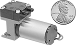
These air compressors/vacuum generators are continuous duty and must be hardwired. They do not require lubricant and produce nonlubricated air.
Overall | ||||||||||||
|---|---|---|---|---|---|---|---|---|---|---|---|---|
| Max. Pressure, psi | Max. Flow Rate @ psi | Vacuum Rating, in. of Hg | Full Load Current | Vol., dBA | Lg. | Wd. | Ht. | For Tube ID | Lubricant Required | Electrical Connection Type | Each | |
12V DC | ||||||||||||
| 3 | 0.019 cfm @ 3 0.042 cfm @ 0 | 12 | 40 mA | 45 | 1 3/4" | 15/16" | 1 5/16" | 0.14" | No | Hardwire | 0000000 | 0000000 |
| 10 | 0.064 cfm @ 10 0.117 cfm @ 0 | 22 | 442 mA | 45 | 3 1/16" | 1 3/16" | 2 3/16" | 0.16" | No | Hardwire | 0000000 | 000000 |
| 12 | 0.148 cfm @ 12 0.254 cfm @ 0 | 25 | 2.3 A | 52 | 4 7/8" | 1 7/8" | 3 1/16" | 0.13" | No | Hardwire | 0000000 | 000000 |
3.5-7V DC | ||||||||||||
| 2 | 0.008 cfm @ 2 0.013 cfm @ 0 | 12 | 32-37 mA | 45 | 1 5/8" | 11/16" | 1" | 0.12" | No | Hardwire | 0000000 | 000000 |