


About Timing Functions
More
About Timer Relays
More
Digital Timers


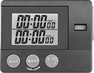

Style S timers have an extra-loud alarm that can be heard over background noise in a typical manufacturing environment.
Timers with a calibration certificate traceable to NIST have been tested to NIST standards to ensure accuracy.
Timers with a memory function automatically return the display to the last programmed time. Good for timing repetitive intervals.
Case | |||||||||||||||
|---|---|---|---|---|---|---|---|---|---|---|---|---|---|---|---|
| Style | Timing Functions | Max. No. of Events | Max. Timer Duration | Max. Alarm Duration | Resolution | Ht. | Wd. | Dp. | Material | Color | Backing Type | Batteries Included | Features | Each | |
Timers | |||||||||||||||
| J | Count Up Count Down Clock | 2 | 3,000 days | 15 sec. | 1/100 sec. | 2 7/8" | 5" | 7/8" | Plastic | Silver | __ | Yes | Built-In Stand | 00000000 | 000000 |
| K | Count Up Count Down | 2 | 24 hrs. | 1 min. | 1 sec. | 3 3/4" | 5" | 1/2" | Plastic | White | __ | Yes | Alarm Memory Function | 00000000 | 00000 |
Timers with Calibration Certificate Traceable to NIST | |||||||||||||||
| J | Count Up Count Down Clock | 2 | 3,000 days | 15 sec. | 1/100 sec. | 2 7/8" | 5" | 7/8" | Plastic | Silver | __ | Yes | Built-In Stand | 00000000 | 00000 |
| R | Count Up Count Down Pause Clock | 2 | 24 hrs. | 1 min. | 1 sec. | 2 1/8" | 2 3/4" | 7/8" | Plastic | Black | Magnetic | Yes | Alarm Built-In Stand Memory Function | 0000000 | 00000 |
| S | Count Up Count Down Pause | 2 | 100 hrs. | 1 min. | 1 sec. | 3" | 3 1/2" | 5/8" | Plastic | White | Magnetic | Yes | Alarm Built-In Stand Memory Function | 0000000 | 00000 |
Stopwatches


Quickly view starts and finishes on a digital screen.
Stopwatches with a calibration certificate traceable to NIST have been tested to NIST standards to ensure accuracy.
Optional clipboards have a clamp to hold Style A stopwatches and a clip to hold paper.
Case | ||||||||||||||
|---|---|---|---|---|---|---|---|---|---|---|---|---|---|---|
| Style | Timing Functions | Max. Timer Duration | Accuracy | Max. No. of Laps Stored | Material | Color | Lens Material | Water Resistance | Backing Type | Batteries Included | Features | Includes | Each | |
Stopwatches | ||||||||||||||
| A | Count Up, Split, Lap | 10 hrs. | ±0.04 sec./hr. | __ | Plastic | Black | Plastic | Water Resistant | __ | Yes | __ | Lanyard | 0000000 | 000000 |
| D | Count Up, Count Down | 100 min. | ±0.08 sec./hr. | __ | Plastic | White | Glass | None | Magnetic | Yes | Alarm | Lanyard | 0000000 | 00000 |
| E | Count Up, Split, Lap, Count Down, Clock | 10 hrs. | ±0.2 sec./hr. | 30 | Plastic | Green | Plastic | None | __ | Yes | Alarm, Thermometer, Humidity Indicator | Lanyard | 0000000 | 00000 |
Stopwatches with Calibration Certificate Traceable to NIST | ||||||||||||||
| H | Count Up, Split, Lap, Pause, Count Down | 10 hrs. | ±0.04 sec./hr. | 300 | Plastic | Gray | Glass | Water Resistant | __ | Yes | Alarm | Lanyard | 0000000 | 00000 |
| Optional Aluminum Clipboard for Style A (9" Wd. × 12 1/2" Lg.) | 0000000 | Each | 000000 |
Dual-Channel DIN-Rail Mount Multifunction Timer Relays

Control two steps of an electrical process from a single relay—with two fully independent channels and 30 different functions, these relays give you a wide range of possibilities. Each channel has its own output, so you can run two different functions (one per circuit) at the same time. Mount them to 35 mm DIN rails (also known as DIN 3 rail) and connect them to lighting systems, conveyors, electric motors, and other systems. These relays are UL Listed, C-UL Listed, and CE Marked, meaning they meet U.S. and international safety standards.
View times, function names, and on/off status for both channels at once using the digital display. You can program these relays with a joystick on the face, which is easier to use than the rotary dials on traditional relays. You can also program them using an Android phone with NFC (near field communication) capability, which is commonly used for mobile payment. Once you select the functions you need, hold the phone against the relay to program.
Connect switches to inputs on these relays to trigger, pause, and reset functions. Turning on a switch connected to the pause input stops functions until the switch is turned off. A switch connected to the reset input will start functions from the beginning. If the relay is actively receiving a signal, the function will restart right away. If there is no signal, the function will stop and reset, so it starts from the beginning the next time it’s triggered. You can use switches to pause or reset both channels at once, or for one channel only.
Use relays with proximity sensor compatibility to activate functions when your sensor is triggered, such as when an object approaches or a liquid level changes. These relays are compatible with both standard styles of sensors, PNP and NPN, and are often used for warning signals, motion-detecting light and heating systems, and automated assembly lines.
Although these relays have 30 different functions, they all fall into 10 categories. Within these categories, you can select different functions to allow you to add a switch, program a delay, or change how the relay responds to a trigger (turning on or off, pausing, or resetting).
Manual Switch Control—Use these functions to turn the relay on and off with a switch.
Fixed On/Off—The on function keeps the relay on whenever input voltage is applied; it will only turn off if the voltage is removed. The off function keeps the relay in an off state, even if input voltage is applied.
Switch-On (Single-Shot)—These functions require a switch to activate the relay, which stays on for the programmed amount of time. For example, lights in a storage room are turned on with a switch and stay on for a set time before turning off.
Delayed Start (Delay-on-Make)—These functions allow you to set how long it takes for the relay to turn on after input voltage is applied. For example, a drill starts pumping lubricant immediately, but it does not start rotating until the set time has elapsed.
Delayed Switch-Off (Delay-on-Break)—These functions use a switch instead of input voltage. When the switch is turned off, the relay remains on for a programmed amount of time before turning off. For example, a projector’s light is turned off with a switch, but its cooling fan continues to run for a set time.
Delayed Switch-On with Delayed Switch-Off—This function uses a switch instead of an input voltage. It allows you to set how long it takes the relay to turn on after a switch is turned on, and how long it will stay on after the switch is turned off. For example, a furnace turns on, but the fan doesn’t start pushing air through the vents until it has been heated. When the furnace turns off, the fan keeps blowing to circulate all the hot air.
Interval—These functions use input voltage to turn on the relay for a programmed amount of time. For example, when a part moving down a conveyor reaches a certain location, a cleaning spray comes on for a set amount of time.
Repeat Cycle—When input voltage is applied, the relay turns on for a duration, then off for the same duration. They alternate between the two until input voltage is removed. For example, a flashing light stays on and off for equal periods of time.
Asymmetrical Repeat Cycle—These functions start with an on-cycle and then have an off-cycle, but these cycles have different durations. The cycles repeat until input voltage is removed. For example, a sprinkler system sprays in short bursts followed by longer rest periods, on and off until input voltage is removed.
Switch-On Asymmetrical Repeat Cycle—These functions require a switch to activate the timing function. The input voltage is applied the whole time, and when you turn the switch on, the relay begins with an on-cycle followed by an off-cycle. These cycles have different durations, and they repeat until you turn the switch off. They could be used to turn on a motor or other system for a short period and then turn it off for a longer rest period, repeating that pattern until the switch is turned off.
![]() For technical drawings and 3-D models, click on a part number.
For technical drawings and 3-D models, click on a part number.
Timing Range | |||||||||||||
|---|---|---|---|---|---|---|---|---|---|---|---|---|---|
| No. of Terminals | Input Voltage | Control Current, mA | Timer Relay Function | No. of | Overall | Switching Current @ 240V AC | Max. Switching Voltage | Ht. | Wd. | Dp. | Features | Each | |
2 Circuit Controlled with 2 Off (Normally Open) and 2 On (Normally Closed)—DPDT | |||||||||||||
| 12 | 12V AC, 24V AC, 12V DC, 24V DC | 8 | Manual Switch Control Fixed On/Off Switch-On (Single-Shot) Delayed Start (Delay-on-Make) Delayed Switch-Off (Delay-on-Break) Delayed Switch-On with Delayed Switch-Off Interval Repeat Cycle Asymmetrical Repeat Cycle Switch-On Asymmetrical Repeat Cycle | 30 | 0.1 sec.-9,999 hrs. | 16A | 240V AC | 3.4" | 1.4" | 2.2" | 2 Individually Programmable Timers, LCD Screen, Proximity Sensor Compatability (PNP and NPN) | 0000000 | 0000000 |
| 12 | 120V AC, 240V AC, 110V DC, 240V DC | 16 | Manual Switch Control Fixed On/Off Switch-On (Single-Shot) Delayed Start (Delay-on-Make) Delayed Switch-Off (Delay-on-Break) Delayed Switch-On with Delayed Switch-Off Interval Repeat Cycle Asymmetrical Repeat Cycle Switch-On Asymmetrical Repeat Cycle | 30 | 0.1 sec.-9,999 hrs. | 16A | 240V AC | 3.4" | 1.4" | 2.2" | 2 Individually Programmable Timers, LCD Screen | 0000000 | 000000 |
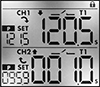
Counters/Hour Meters

Keep track of time while counting events. Units have two displays: one that receives input from a sensor, encoder, or switch and another that counts hours.
![]() For technical drawings and 3-D models, click on a part number.
For technical drawings and 3-D models, click on a part number.
Electrically Actuated Hour Meters with Output Relay

Display running time on a machine so you can schedule preventative maintenance. These counters have two displays. One display shows the total running time and cannot be reset; the other shows the time elapsed since the last maintenance and can be wired for remote reset. The output relay turns on an indicator light and sends a signal to another device when the counter reaches a set point. The signal can start/stop a process or trigger an alarm.
Overall | |||||||||||
|---|---|---|---|---|---|---|---|---|---|---|---|
| Resettable | Counting Direction | No. of Digits | No. of Set Points | For Panel Cutout Dia. | Dp. | Dia. | Operating Voltage | Output Relay Current | Environmental Rating | Each | |
Press On | |||||||||||
Wire Leads | |||||||||||
| No | Up | 6 | 1 | 2" | 1.7" | 2.3" | 85-265V AC, 90-360V DC | 0.2 A @ 265 V AC, 0.2 A @ 40 V DC | IP67 | 00000000 | 0000000 |
| No | Up | 6 | 1 | 2" | 1.7" | 2.3" | 10-40V DC | 0.2 A @ 265 V AC, 0.2 A @ 40 V DC | IP67 | 00000000 | 000000 |