


Stepper Motor Controllers and Drivers
Tell your stepper motor how far and fast to go by adding a controller and driver to your system. A controller is similar to a PLC—they store and run programs and send signals to a driver. These controllers have commands specifically for stepper motors such as number of steps and direction. The driver delivers power to the motor based on the signals from the controller. Choose from either an individual driver or a combination controller/driver.
![]() For technical drawings and 3-D models, click on a part number.
For technical drawings and 3-D models, click on a part number.
Drivers can be set to different step resolutions. The higher the number of step resolution settings, the greater the flexibility you have for determining the size of the motor’s step.
Choose a driver rated at or below your motor's maximum current.
Step resolution determines the size of the step a motor takes. For example, setting a 1/128 step resolution on your driver divides one full step into 128 smaller steps. The smaller the steps your motor takes the more smoothly and precisely it will move.
O'all | |||||||||||
|---|---|---|---|---|---|---|---|---|---|---|---|
| Current per Phase, A | Voltage | Step Resolution | No. of Step Resolution Settings | Max. Step Frequency, MHz | For Stepper Motor Polarity | Wire Connection Type | Lg. | Wd. | Ht. | Each | |
| 0.3-2.2 | 12-48V DC | 1; 1/2; 1/10; 1/25; 1/64; 1/100 | 6 | 2 | Bipolar | Screw Terminals | 2.6" | 3.7" | 0.8" | 00000000 | 0000000 |
| 2.35-8 | 24-75V DC | 1; 1/2; 1/10; 1/25; 1/64; 1/100 | 6 | 2 | Bipolar | Screw Terminals | 3.3" | 4.7" | 1.3" | 00000000 | 000000 |
| 0.4-8 | 90-240V AC | 1; 1/2; 1/4; 1/5; 1/8; 1/10; 1/16; 1/20; 1/25; 1/32; 1/40; 1/50; 1/64; 1/100; 1/125; 1/128 | 16 | 2 | Bipolar | Screw Terminals | 4.7" | 7" | 2.1" | 00000000 | 000000 |
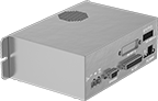
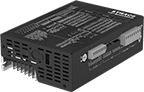
Simplify setup with these single units. The controller and driver are combined, so you can determine all your settings from one device including number of steps, direction, and step resolution. They have multiple inputs and outputs to communicate with more than just a motor. Connect sensors and switches or link multiple controllers together to coordinate movements between motors.
Choose a controller/driver rated at or below your motor’s maximum current.
Encoder-compatible controller/drivers are best when relative positioning is critical, such as coordinating motion in a multi-axis system. They connect to an encoder (not included), which monitors the position of the motor's shaft and reports back to the controller.
Step resolution determines the size of the step a motor takes. For example, setting a 1/128 step resolution on your controller/driver divides one full step into 128 smaller steps. The smaller the steps your motor takes the more smoothly and precisely it will move.
No. of Inputs/Outputs | O'all | |||||||||||||
|---|---|---|---|---|---|---|---|---|---|---|---|---|---|---|
| Current per Phase, A | Voltage | Step Resolution | No. of Step Resolution Settings | Max. Step Frequency, MHz | Digital (Input) | Digital (Output) | For Stepper Motor Polarity | Lg. | Wd. | Ht. | Includes | Features | Each | |
| 0.1-6 | 12-48V DC | 1 to 1/256 | 25,501 | 2 | 8 | 4 | Bipolar | 2.4" | 3.9" | 0.9" | I/O Cable | __ | 0000000 | 0000000 |
| 0.1-10 | 24-80V DC | 1 to 1/256 | 25,501 | 2 | 8 | 4 | Bipolar | 3" | 5" | 1.75" | __ | Encoder Compatible | 00000000 | 000000 |
| 0.5-6 | 94-135V AC | 1 to 1/256 | 25,501 | 2 | 7 | 3 | Bipolar | 4.7" | 6.4" | 2.3" | __ | __ | 00000000 | 00000000 |